
User Manual
Page 1
F1A75-V PRO Motherboard
F1A75-V PRO Motherboard
User Manual
Page 3
DIGI+ VRM 1-2 1.3.3 ASUS Digital Power Design 1-3 1.3.4 ASUS Exclusive Features 1-3 Chapter 2: Hardware information 2.1 Before you proceed 2-1 2.2 Motherboard overview 2-2 2.2.1 Motherboard layout 2-2 2.2.2 Layout contents 2-3 2.2.3 Placement direction 2-4 2.2.4 Screw holes 2-4 2.3 Accelerated Processing Unit (APU...connectors 2-27 2.8.4 ASUS Q-Connector (system panel 2-34 2.9 Onboard LEDs 2-35 2.10 Starting up for the first time 2-37 2.11 Turning off the computer 2-37 iii Contents Notices...vi Safety information...vii About this guide...viii F1A75-V PRO specifications summary x ...
DIGI+ VRM 1-2 1.3.3 ASUS Digital Power Design 1-3 1.3.4 ASUS Exclusive Features 1-3 Chapter 2: Hardware information 2.1 Before you proceed 2-1 2.2 Motherboard overview 2-2 2.2.1 Motherboard layout 2-2 2.2.2 Layout contents 2-3 2.2.3 Placement direction 2-4 2.2.4 Screw holes 2-4 2.3 Accelerated Processing Unit (APU...connectors 2-27 2.8.4 ASUS Q-Connector (system panel 2-34 2.9 Onboard LEDs 2-35 2.10 Starting up for the first time 2-37 2.11 Turning off the computer 2-37 iii Contents Notices...vi Safety information...vii About this guide...viii F1A75-V PRO specifications summary x ...
User Manual
Page 7
...are unplugged. • Seek professional assistance before using , contact your retailer. If you add a device. • Before connecting or removing signal cables from the motherboard, ensure that your area. If possible, disconnect all power cables from the system, ensure that the battery should not be placed in municipal waste. Operation...clips, screws, and staples away from the electrical outlet before the signal cables are using an adapter or extension cord. DO NOT throw the motherboard in our products at ASUS REACH website at http://crs.asus.com/english/REACH.htm.
...are unplugged. • Seek professional assistance before using , contact your retailer. If you add a device. • Before connecting or removing signal cables from the motherboard, ensure that your area. If possible, disconnect all power cables from the system, ensure that the battery should not be placed in municipal waste. Operation...clips, screws, and staples away from the electrical outlet before the signal cables are using an adapter or extension cord. DO NOT throw the motherboard in our products at ASUS REACH website at http://crs.asus.com/english/REACH.htm.
User Manual
Page 8
... by your dealer. Where to find more information Refer to the ASUS contact information. 2. These documents are also provided. • Chapter 4: Software support This chapter describes the contents of the motherboard and the new technology it supports. • Chapter 2: Hardware...documentation, such as warranty flyers, that you need when installing and configuring the motherboard. It includes description of the standard package. ASUS websites The ASUS website provides updated information on the motherboard. • Chapter 3: BIOS setup This chapter tells how to perform when ...
... by your dealer. Where to find more information Refer to the ASUS contact information. 2. These documents are also provided. • Chapter 4: Software support This chapter describes the contents of the motherboard and the new technology it supports. • Chapter 2: Hardware...documentation, such as warranty flyers, that you need when installing and configuring the motherboard. It includes description of the standard package. ASUS websites The ASUS website provides updated information on the motherboard. • Chapter 3: BIOS setup This chapter tells how to perform when ...
User Manual
Page 15
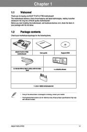
... package with the list below. 1.2 Package contents Check your retailer. • The illustrated items above are for reference only. Chapter 1 Chapter 1: Chapter 1 Product introduction 1.1 Welcome! ASUS F1A75-V PRO 1-1 Before you for the following items. User Manual ASUS F1A75-V PRO motherboard User guide Support DVD 2 x Serial ATA 6.0 Gb/s cables with different models. Thank you start installing the...
... package with the list below. 1.2 Package contents Check your retailer. • The illustrated items above are for reference only. Chapter 1 Chapter 1: Chapter 1 Product introduction 1.1 Welcome! ASUS F1A75-V PRO 1-1 Before you for the following items. User Manual ASUS F1A75-V PRO motherboard User guide Support DVD 2 x Serial ATA 6.0 Gb/s cables with different models. Thank you start installing the...
User Manual
Page 16
... scalability, faster data retrieval, double the bandwidth of current bus systems. 100% All High-quality Conductive Polymer Capacitors This motherboard uses all high-quality conductive polymer capacitors for durability, improved lifespan, and enhanced thermal capacity. 1.3.2 Dual Intelligent Processors ...overclocking potential. 1-2 Chapter 1: Product Introduction the latest connectivity standard. DIGI+ VRM The world's first Dual Intelligent Processors from ASUS pioneered the use of Dual Intelligent Processor 2 with DIGI+ VRM launches power delivery into a digital standard with USB 2.0 ...
... scalability, faster data retrieval, double the bandwidth of current bus systems. 100% All High-quality Conductive Polymer Capacitors This motherboard uses all high-quality conductive polymer capacitors for durability, improved lifespan, and enhanced thermal capacity. 1.3.2 Dual Intelligent Processors ...overclocking potential. 1-2 Chapter 1: Product Introduction the latest connectivity standard. DIGI+ VRM The world's first Dual Intelligent Processors from ASUS pioneered the use of Dual Intelligent Processor 2 with DIGI+ VRM launches power delivery into a digital standard with USB 2.0 ...
User Manual
Page 18
... and easy to achieve a quiet and cool environment. Fan Xpert ASUS Fan Xpert intelligently allows you to switch back and forth between different utilities. ASUS Q-Design ASUS Q-Design enhances your motherboard against 1-4 Chapter 1: Product Introduction Refer to different ambient temperatures caused...visual enjoyment for details. Chapter 1 performance enthusiasts who demand a more intricate system setup. ASUS Anti-Surge Protection This special design protects expensive devices and the motherboard from switching power supply unit (PSU). All of fan speed to install on your USB ...
... and easy to achieve a quiet and cool environment. Fan Xpert ASUS Fan Xpert intelligently allows you to switch back and forth between different utilities. ASUS Q-Design ASUS Q-Design enhances your motherboard against 1-4 Chapter 1: Product Introduction Refer to different ambient temperatures caused...visual enjoyment for details. Chapter 1 performance enthusiasts who demand a more intricate system setup. ASUS Anti-Surge Protection This special design protects expensive devices and the motherboard from switching power supply unit (PSU). All of fan speed to install on your USB ...
User Manual
Page 19
...personalize your favorite photos into 256-color boot logos to energy consumptions. ErP ready The motherboard is a user-friendly utility that contains the BIOS file. ASUS F1A75-V PRO 1-5 ASUS EZ Flash 2 ASUS EZ Flash 2 is European Union´s Energy-related Products (ErP) ready, and ...ErP requires products to meet certain energy efficiency requirements in line with ASUS vision of the product and thus mitigate...
...personalize your favorite photos into 256-color boot logos to energy consumptions. ErP ready The motherboard is a user-friendly utility that contains the BIOS file. ASUS F1A75-V PRO 1-5 ASUS EZ Flash 2 ASUS EZ Flash 2 is European Union´s Energy-related Products (ErP) ready, and ...ErP requires products to meet certain energy efficiency requirements in line with ASUS vision of the product and thus mitigate...
User Manual
Page 21
... cord is detached from the power supply. Chapter 2: Chapter 2 Hardware information 2.1 Before you proceed Take note of the following precautions before you install motherboard components or change any motherboard settings. • Unplug the power cord from the wall socket before touching any component. • Before handling components, use a grounded wrist strap or... or a metal object, such as the power supply case, to avoid damaging them due to static electricity. • Hold components by the edges to the motherboard, peripherals, or components. Chapter 2 ASUS F1A75-V PRO 2-1
... cord is detached from the power supply. Chapter 2: Chapter 2 Hardware information 2.1 Before you proceed Take note of the following precautions before you install motherboard components or change any motherboard settings. • Unplug the power cord from the wall socket before touching any component. • Before handling components, use a grounded wrist strap or... or a metal object, such as the power supply case, to avoid damaging them due to static electricity. • Hold components by the edges to the motherboard, peripherals, or components. Chapter 2 ASUS F1A75-V PRO 2-1
User Manual
Page 22
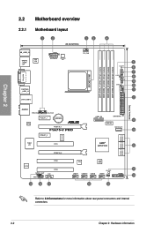
... 8 9 10 1 2 30.5cm(12.0in) AUDIO PWR_FAN CHA_FAN1 PCIEX1_1 Lithium Cell CMOS Power RTL 8111E PCIEX16_1 F1A75-V PRO PCIEX1_2 ICS477D Super I/O PCI1 PCIEX16_2 USB3_56 EATXPWR 11 ASM1061 SATA6G_E1 12 AMD® A75 FCH 12 SATA6G_2 SATA6G_4 SATA6G_6 ... Refer to 2.8 Connectors for more information about rear panel connectors and internal connectors. 2-2 Chapter 2: Hardware information Chapter 2 2.2 Motherboard overview 2.2.1 Motherboard layout 1 2 24.4cm(9.6in) 13 KB_USB3_34 SPDIFO _HDMI _DP ASM 1042 EATX12V DIGI+VRM EPU CPU_FAN SOCKET FM1 DVI_VGA ESATA6G ...
... 8 9 10 1 2 30.5cm(12.0in) AUDIO PWR_FAN CHA_FAN1 PCIEX1_1 Lithium Cell CMOS Power RTL 8111E PCIEX16_1 F1A75-V PRO PCIEX1_2 ICS477D Super I/O PCI1 PCIEX16_2 USB3_56 EATXPWR 11 ASM1061 SATA6G_E1 12 AMD® A75 FCH 12 SATA6G_2 SATA6G_4 SATA6G_6 ... Refer to 2.8 Connectors for more information about rear panel connectors and internal connectors. 2-2 Chapter 2: Hardware information Chapter 2 2.2 Motherboard overview 2.2.1 Motherboard layout 1 2 24.4cm(9.6in) 13 KB_USB3_34 SPDIFO _HDMI _DP ASM 1042 EATX12V DIGI+VRM EPU CPU_FAN SOCKET FM1 DVI_VGA ESATA6G ...
User Manual
Page 24
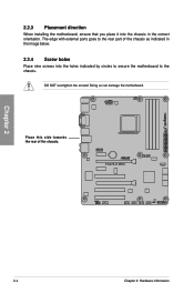
Place this side towards the rear of the chassis as indicated in the image below. 2.2.4 Screw holes Place nine screws into the chassis in the correct orientation. DO NOT overtighten the screws! F1A75-V PRO Chapter 2 2-4 Chapter 2: Hardware information The edge with external ports goes to the rear part of the chassis. Doing so can damage the motherboard. 2.2.3 Placement direction When installing the motherboard, ensure that you place it into the holes indicated by circles to secure the motherboard to the chassis.
Place this side towards the rear of the chassis as indicated in the image below. 2.2.4 Screw holes Place nine screws into the chassis in the correct orientation. DO NOT overtighten the screws! F1A75-V PRO Chapter 2 2-4 Chapter 2: Hardware information The edge with external ports goes to the rear part of the chassis. Doing so can damage the motherboard. 2.2.3 Placement direction When installing the motherboard, ensure that you place it into the holes indicated by circles to secure the motherboard to the chassis.
User Manual
Page 25
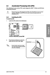
... NOT force the APU into the socket to prevent bending the pins and damaging the APU! 2.3.1 Installing the APU To install the APU: 1. Chapter 2 ASUS F1A75-V PRO 2-5 2.3 Accelerated Processing Unit (APU) This motherboard comes with an FM1 socket designed for the FM1 socket. Otherwise, the APU will not fit in only one correct orientation.
... NOT force the APU into the socket to prevent bending the pins and damaging the APU! 2.3.1 Installing the APU To install the APU: 1. Chapter 2 ASUS F1A75-V PRO 2-5 2.3 Accelerated Processing Unit (APU) This motherboard comes with an FM1 socket designed for the FM1 socket. Otherwise, the APU will not fit in only one correct orientation.
User Manual
Page 27
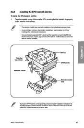
Place the heatsink on top of the installed CPU, ensuring that a Thermal Interface Material is already installed on the motherboard upon purchase. • You do not match the CPU documentation, follow the latter. If the instructions in this section do not ...installing other motherboard components. • If you purchased a separate CPU heatsink and fan assembly, ensure that the heatsink fits properly on the retention module base. • The retention module base is properly applied to the CPU heatsink or CPU before you install the heatsink and fan assembly. ASUS F1A75-V PRO 2-7 ...
Place the heatsink on top of the installed CPU, ensuring that a Thermal Interface Material is already installed on the motherboard upon purchase. • You do not match the CPU documentation, follow the latter. If the instructions in this section do not ...installing other motherboard components. • If you purchased a separate CPU heatsink and fan assembly, ensure that the heatsink fits properly on the retention module base. • The retention module base is properly applied to the CPU heatsink or CPU before you install the heatsink and fan assembly. ASUS F1A75-V PRO 2-7 ...
User Manual
Page 29
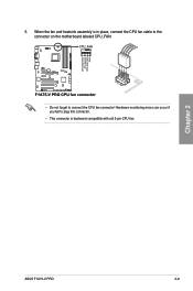
When the fan and heatsink assembly is in place, connect the CPU fan cable to plug this connector. • This connector is backward compatible with old 3-pin CPU fan. Hardware monitoring errors can occur if you fail to the connector on the motherboard labeled CPU_FAN. CPU FAN PWM CPU FAN IN CPU FAN PWR GND Chapter 2 5. ASUS F1A75-V PRO 2-9 CPU_FAN F1A75-V PRO • Do not forget to connect the CPU fan connector!
When the fan and heatsink assembly is in place, connect the CPU fan cable to plug this connector. • This connector is backward compatible with old 3-pin CPU fan. Hardware monitoring errors can occur if you fail to the connector on the motherboard labeled CPU_FAN. CPU FAN PWM CPU FAN IN CPU FAN PWR GND Chapter 2 5. ASUS F1A75-V PRO 2-9 CPU_FAN F1A75-V PRO • Do not forget to connect the CPU fan connector!
User Manual
Page 30
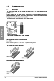
... sockets. Two DIMMs (dual-channel operation): Four DIMMs (dual-channel operation): 2-10 Chapter 2: Hardware information The figure illustrates the location of the DDR3 DIMM sockets: F1A75-V PRO F1A75-V PRO 240-pin DDR3 DIMM sockets Recommended memory configurations One DIMM: Install one memory module in any slot as a DDR2 DIMM but is notched differently to... on a DDR2 DIMM socket. A DDR3 module has the same physical dimensions as a single-channel operation. DIMM_A1 DIMM_A2 DIMM_B1 DIMM_B2 Chapter 2 2.4 System memory 2.4.1 Overview The motherboard comes with less power consumption.
... sockets. Two DIMMs (dual-channel operation): Four DIMMs (dual-channel operation): 2-10 Chapter 2: Hardware information The figure illustrates the location of the DDR3 DIMM sockets: F1A75-V PRO F1A75-V PRO 240-pin DDR3 DIMM sockets Recommended memory configurations One DIMM: Install one memory module in any slot as a DDR2 DIMM but is notched differently to... on a DDR2 DIMM socket. A DDR3 module has the same physical dimensions as a single-channel operation. DIMM_A1 DIMM_A2 DIMM_B1 DIMM_B2 Chapter 2 2.4 System memory 2.4.1 Overview The motherboard comes with less power consumption.
User Manual
Page 31
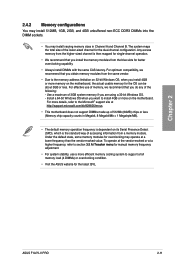
...varying memory sizes in Megabit, 8 Megabit/Mb = 1 Megabyte/MB). • The default memory operation frequency is dependent on the motherboard, the actual usable memory for the dual-channel configuration. Use a maximum of accessing information from the higher-sized channel is the ... to support a full memory load (4 DIMMs) or overclocking condition. • Visit the ASUS website for better overclocking capability. • Always install DIMMs with the same CAS latency. Chapter 2 ASUS F1A75-V PRO 2-11 The system maps the total size of the following: - For effective use a more...
...varying memory sizes in Megabit, 8 Megabit/Mb = 1 Megabyte/MB). • The default memory operation frequency is dependent on the motherboard, the actual usable memory for the dual-channel configuration. Use a maximum of accessing information from the higher-sized channel is the ... to support a full memory load (4 DIMMs) or overclocking condition. • Visit the ASUS website for better overclocking capability. • Always install DIMMs with the same CAS latency. Chapter 2 ASUS F1A75-V PRO 2-11 The system maps the total size of the following: - For effective use a more...
User Manual
Page 32
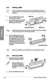
... adding or removing DIMMs or other system components. Remove the DIMM from the socket. 2-12 Chapter 2: Hardware information Chapter 2 2.4.3 Installing a DIMM Ensure to both the motherboard and the components. 1.
... adding or removing DIMMs or other system components. Remove the DIMM from the socket. 2-12 Chapter 2: Hardware information Chapter 2 2.4.3 Installing a DIMM Ensure to both the motherboard and the components. 1.
User Manual
Page 33
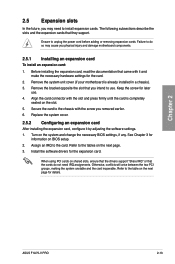
... the software settings. 1. ASUS F1A75-V PRO 2-13 Chapter 2 2.5 Expansion slots In the future, you intend to use . 4. Keep the screw for information on the next page for the card. 2. Align the card connector with the screw you physical injury and damage motherboard components. 2.5.1 Installing an ...any. Assign an IRQ to unplug the power cord before adding or removing expansion cards. Remove the system unit cover (if your motherboard is completely seated on the next page. 3. Ensure to the card. Turn on shared slots, ensure that the drivers support "Share...
... the software settings. 1. ASUS F1A75-V PRO 2-13 Chapter 2 2.5 Expansion slots In the future, you intend to use . 4. Keep the screw for information on the next page for the card. 2. Align the card connector with the screw you physical injury and damage motherboard components. 2.5.1 Installing an ...any. Assign an IRQ to unplug the power cord before adding or removing expansion cards. Remove the system unit cover (if your motherboard is completely seated on the next page. 3. Ensure to the card. Turn on shared slots, ensure that the drivers support "Share...
User Manual
Page 34
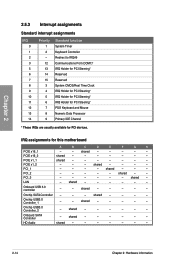
... for PCI Steering* IRQ Holder for PCI Steering* PS/2 Keyboard and Mouse Numeric Data Processor Primary IDE Channel * These IRQs are usually available for this motherboard PCIE x16_1 PCIE x16_2 PCIE x1_1 PCIE x1_2 PCI_1 PCI_2 PCI_3 LAN A B C D E F G H - -
... for PCI Steering* IRQ Holder for PCI Steering* PS/2 Keyboard and Mouse Numeric Data Processor Primary IDE Channel * These IRQs are usually available for this motherboard PCIE x16_1 PCIE x16_2 PCIE x1_1 PCIE x1_2 PCI_1 PCI_2 PCI_3 LAN A B C D E F G H - -
User Manual
Page 35
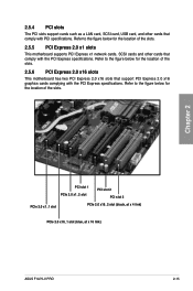
... 3 PCIe 2.0 x1_1 slot PCIe 2.0 x16_2 slot (black, at x 4 link) PCIe 2.0 x16_1 slot (blue, at x 16 link) ASUS F1A75-V PRO 2-15 Refer to the figure below for the location of the slots. 2.5.6 PCI Express 2.0 x16 slots This motherboard has two PCI Express 2.0 x16 slots that support PCI Express 2.0 x16 graphics cards complying with the PCI...
... 3 PCIe 2.0 x1_1 slot PCIe 2.0 x16_2 slot (black, at x 4 link) PCIe 2.0 x16_1 slot (blue, at x 16 link) ASUS F1A75-V PRO 2-15 Refer to the figure below for the location of the slots. 2.5.6 PCI Express 2.0 x16 slots This motherboard has two PCI Express 2.0 x16 slots that support PCI Express 2.0 x16 graphics cards complying with the PCI...


