
User Manual
Page 13
...APU (Accelerated Processing Unit) combines processing power and advanced DirectX 11 graphics in one small, energy-efficient design to 5GT/s. ASUS F1A75-M PRO 1-1 The motherboard delivers a host of new features and latest technologies, making it , check the items in the long...Before you for the following items. Motherboard Cables Accessories Application DVD Documentations ASUS F1A75-M PRO motherboard 2 x Serial ATA 6.0Gb/s cables 1 x Q-Shield ASUS motherboard Support DVD User Manual If any of ASUS quality motherboards! Chapter 1 Product introduction 1.1 Welcome! Thank you start ...
...APU (Accelerated Processing Unit) combines processing power and advanced DirectX 11 graphics in one small, energy-efficient design to 5GT/s. ASUS F1A75-M PRO 1-1 The motherboard delivers a host of new features and latest technologies, making it , check the items in the long...Before you for the following items. Motherboard Cables Accessories Application DVD Documentations ASUS F1A75-M PRO motherboard 2 x Serial ATA 6.0Gb/s cables 1 x Q-Shield ASUS motherboard Support DVD User Manual If any of ASUS quality motherboards! Chapter 1 Product introduction 1.1 Welcome! Thank you start ...

User Manual
Page 15
...potential. This remarkable memory rescue tool requires a mere push of the button to overclock without exiting or rebooting the OS; ASUS F1A75-M PRO 1-3 ASUS Exclusive Features ASUS TurboV Feel the adrenaline rush of two onboard chips - guickly ensures memory boot compatibility. MemOK! 1.3.3 1.3.4 EPU Tap into... can achieve extreme yet stable overclocking results with the most flexible power adjustment than traditional analog power design.With ASUS DIGI+ VRM, users can easily adjust power phase management voltages and frequency modulation via diverse settings through a ...
...potential. This remarkable memory rescue tool requires a mere push of the button to overclock without exiting or rebooting the OS; ASUS F1A75-M PRO 1-3 ASUS Exclusive Features ASUS TurboV Feel the adrenaline rush of two onboard chips - guickly ensures memory boot compatibility. MemOK! 1.3.3 1.3.4 EPU Tap into... can achieve extreme yet stable overclocking results with the most flexible power adjustment than traditional analog power design.With ASUS DIGI+ VRM, users can easily adjust power phase management voltages and frequency modulation via diverse settings through a ...

User Manual
Page 17
... easy to install on your motherboard against Electronic Magnetic Interference (EMI). C.P.R. ASUS F1A75-M PRO 1-5 ASUS Q-Design ASUS Q-Design enhances your favorite photos into 256-color boot logos to overclocking failure. ASUS CrashFree BIOS 3 ASUS CrashFree BIOS 3 is in variety of useful profiles offer flexible controls of... and Q-Code design speed up and simplify the DIY process! All of the product and thus mitigate environmental impacts. ASUS EZ Flash 2 ASUS EZ Flash 2 is European Union´s Energy-related Products (ErP) ready, and ErP requires products to meet certain...
... easy to install on your motherboard against Electronic Magnetic Interference (EMI). C.P.R. ASUS F1A75-M PRO 1-5 ASUS Q-Design ASUS Q-Design enhances your favorite photos into 256-color boot logos to overclocking failure. ASUS CrashFree BIOS 3 ASUS CrashFree BIOS 3 is in variety of useful profiles offer flexible controls of... and Q-Code design speed up and simplify the DIY process! All of the product and thus mitigate environmental impacts. ASUS EZ Flash 2 ASUS EZ Flash 2 is European Union´s Energy-related Products (ErP) ready, and ErP requires products to meet certain...

User Manual
Page 19
Doing so can damage the motherboard. Place this side towards the rear of the chassis as indicated in the image below. 1.5.2 Screw holes Place eight screws into the chassis in the correct orientation. DO NOT overtighten the screws! F1A75-M PRO ASUS F1A75-M PRO 1-7 1.5 Motherboard overview 1.5.1 Placement direction When installing the motherboard, ensure that you place it into the holes indicated by circles to secure the motherboard to the rear part of the chassis. The edge with external ports goes to the chassis.
Doing so can damage the motherboard. Place this side towards the rear of the chassis as indicated in the image below. 1.5.2 Screw holes Place eight screws into the chassis in the correct orientation. DO NOT overtighten the screws! F1A75-M PRO ASUS F1A75-M PRO 1-7 1.5 Motherboard overview 1.5.1 Placement direction When installing the motherboard, ensure that you place it into the holes indicated by circles to secure the motherboard to the rear part of the chassis. The edge with external ports goes to the chassis.

User Manual
Page 21
DO NOT force the APU into the socket to prevent bending the pins and damaging the APU! F1A75-M PRO F1A75-M PRO processor socket FM1 2. 1.6 Accelerated Processing Unit (APU) This motherboard comes with an FM1 socket designed for the FM1 socket. series accelerated processors with a...the APU into the socket to prevent bending the pins and damaging the APU! 1.6.1 Installing the APU To install a APU: 1. Small triangle Gold triangle ASUS F1A75-M PRO 1-9 The APU fits in place. Press the lever sideways to a 90°-100° angle. The APU fits only in completely. 3. Ensure ...
DO NOT force the APU into the socket to prevent bending the pins and damaging the APU! F1A75-M PRO F1A75-M PRO processor socket FM1 2. 1.6 Accelerated Processing Unit (APU) This motherboard comes with an FM1 socket designed for the FM1 socket. series accelerated processors with a...the APU into the socket to prevent bending the pins and damaging the APU! 1.6.1 Installing the APU To install a APU: 1. Small triangle Gold triangle ASUS F1A75-M PRO 1-9 The APU fits in place. Press the lever sideways to a 90°-100° angle. The APU fits only in completely. 3. Ensure ...

User Manual
Page 23
Place the heatsink on top of the retention bracket to the retention module base. 1 2 3 4 5 ASUS F1A75-M PRO 1-11 If the instructions in this section do not have to remove the retention module base when installing the CPU or installing other motherboard components. &#...
Place the heatsink on top of the retention bracket to the retention module base. 1 2 3 4 5 ASUS F1A75-M PRO 1-11 If the instructions in this section do not have to remove the retention module base when installing the CPU or installing other motherboard components. &#...

User Manual
Page 25
...the following: - For effective use a more efficient memory cooling system to section 2.4 Ai Tweaker menu for the latest QVL. Visit the ASUS website at a lower frequency than the vendor-marked value. For optimum compatibility, we recommend that you obtain memory modules from a memory module... of memory, we recommend that you install 4GB or more memory on the motherboard, the actual usable memory for the dual-channel configuration. ASUS F1A75-M PRO 1-13 To operate at the vendor-marked or at a higher frequency, refer to support a full memory load (4 DIMMs) or overclocking...
...the following: - For effective use a more efficient memory cooling system to section 2.4 Ai Tweaker menu for the latest QVL. Visit the ASUS website at a lower frequency than the vendor-marked value. For optimum compatibility, we recommend that you obtain memory modules from a memory module... of memory, we recommend that you install 4GB or more memory on the motherboard, the actual usable memory for the dual-channel configuration. ASUS F1A75-M PRO 1-13 To operate at the vendor-marked or at a higher frequency, refer to support a full memory load (4 DIMMs) or overclocking...

User Manual
Page 27
... that they support. Failure to do not need to the card. 3. Remove the system unit cover (if your motherboard is completely seated on BIOS setup. 2. ASUS F1A75-M PRO 1-15 Unplug the power cord before adding or removing expansion cards. When using PCI cards on the system and change the necessary BIOS settings, if...
... that they support. Failure to do not need to the card. 3. Remove the system unit cover (if your motherboard is completely seated on BIOS setup. 2. ASUS F1A75-M PRO 1-15 Unplug the power cord before adding or removing expansion cards. When using PCI cards on the system and change the necessary BIOS settings, if...

User Manual
Page 29
... a Local Area Network (LAN) through a network hub. Rear Speaker Out port (black). This port connects to a microphone. 10. Line Out port (lime). Microphone port (pink). ASUS F1A75-M PRO 1-17 1.10 1.10.1 1 Connectors Rear panel ports 2 3 4 56 78 15 14 13 12 11 10 9 1. In the 4, 6 and 8-channel configurations, the function of this port...
... a Local Area Network (LAN) through a network hub. Rear Speaker Out port (black). This port connects to a microphone. 10. Line Out port (lime). Microphone port (pink). ASUS F1A75-M PRO 1-17 1.10 1.10.1 1 Connectors Rear panel ports 2 3 4 56 78 15 14 13 12 11 10 9 1. In the 4, 6 and 8-channel configurations, the function of this port...

User Manual
Page 31
...GND CHA_FAN2 CHA FAN PWM CHA_FAN1 CHA FAN IN CHA FAN PWR GND GND CHA FAN PWR CHA FAN IN CHA FAN PWM F1A75-M PRO PWR_FAN GND +12V Rotation F1A75-M PRO Fan connectors DO NOT forget to connect the fan cables to the fan connectors on the fan connectors. • The CPU_FAN ... Xpert feature. • If you plug the rear chassis fan cable to the motherboard connector labeled CHA_FAN1/2 for better thermal environment. ASUS F1A75-M PRO 1-19 These are not jumpers! Power, CPU and chassis fan connectors (3-pin PWR FAN, 4-pin CPU_FAN, and 4-pin CHA_FAN1/2) Connect the fan cables ...
...GND CHA_FAN2 CHA FAN PWM CHA_FAN1 CHA FAN IN CHA FAN PWR GND GND CHA FAN PWR CHA FAN IN CHA FAN PWM F1A75-M PRO PWR_FAN GND +12V Rotation F1A75-M PRO Fan connectors DO NOT forget to connect the fan cables to the fan connectors on the fan connectors. • The CPU_FAN ... Xpert feature. • If you plug the rear chassis fan cable to the motherboard connector labeled CHA_FAN1/2 for better thermal environment. ASUS F1A75-M PRO 1-19 These are not jumpers! Power, CPU and chassis fan connectors (3-pin PWR FAN, 4-pin CPU_FAN, and 4-pin CHA_FAN1/2) Connect the fan cables ...

User Manual
Page 33
... disk drives to IDE mode by default. Serial port connector (10-1 pin COM1) This connector is purchased separately. ASUS F1A75-M PRO 1-21 SATA6G_5 SATA6G_6 GND RSATA_RXN5 RSATA_RXP5 GND RSATA_TXN5 RSATA_TXP5 GND GND RSATA_RXN6 RSATA_RXP6 GND RSATA_TXN6 RSATA_TXP6 GND SATA6G_3 SATA6G_4 GND ... XP Service Pack 3 or later version before using these connectors. See section 2.5.2 SATA Configuration for details. 4. COM1 PIN 1 F1A75-M PRO F1A75-M PRO Serial port (COM1) connector The COM module is for Serial ATA hard disk drives and optical disc drives. Connect the serial port ...
... disk drives to IDE mode by default. Serial port connector (10-1 pin COM1) This connector is purchased separately. ASUS F1A75-M PRO 1-21 SATA6G_5 SATA6G_6 GND RSATA_RXN5 RSATA_RXP5 GND RSATA_TXN5 RSATA_TXP5 GND GND RSATA_RXN6 RSATA_RXP6 GND RSATA_TXN6 RSATA_TXP6 GND SATA6G_3 SATA6G_4 GND ... XP Service Pack 3 or later version before using these connectors. See section 2.5.2 SATA Configuration for details. 4. COM1 PIN 1 F1A75-M PRO F1A75-M PRO Serial port (COM1) connector The COM module is for Serial ATA hard disk drives and optical disc drives. Connect the serial port ...

User Manual
Page 35
...1 PIN 1 MIC2 MICPWR Line out_R NC Line out_L PORT1 L PORT1 R PORT2 R SENSE_SEND PORT2 L F1A75-M PRO HD-audio-compliant Legacy AC'97 pin definition compliant definition F1A75-M PRO Front panel audio connector • We recommend that supports either High Definition Audio or AC`97 audio standard.... for a chassis-mounted front panel audio I /O module cable to this connector, set the Front Panel Type item in the BIOS to [HD]. ASUS F1A75-M PRO 1-23 Front panel audio connector (10-1 pin AAFP) This connector is purchased separately. 7. The S/PDIF module is for details. • The...
...1 PIN 1 MIC2 MICPWR Line out_R NC Line out_L PORT1 L PORT1 R PORT2 R SENSE_SEND PORT2 L F1A75-M PRO HD-audio-compliant Legacy AC'97 pin definition compliant definition F1A75-M PRO Front panel audio connector • We recommend that supports either High Definition Audio or AC`97 audio standard.... for a chassis-mounted front panel audio I /O module cable to this connector, set the Front Panel Type item in the BIOS to [HD]. ASUS F1A75-M PRO 1-23 Front panel audio connector (10-1 pin AAFP) This connector is purchased separately. 7. The S/PDIF module is for details. • The...

User Manual
Page 37
...will appear during the tuning process, the system continues memory tuning after turning on the ASUS website at www.asus.com after the whole tuning process, the DRAM_LED lights continuously. F1A75-M PRO F1A75-M PRO MemOK! The blinking speed of failsafe settings. Press and hold the MemOK! switch does...recommend that are incompatible with ones recommended in the Memory QVL (Qualified Vendors Lists) in this user manual or on the computer. ASUS F1A75-M PRO 1-25 switch lights continuously. switch • Refer to boot and load BIOS default settings. If the test fails, the system ...
...will appear during the tuning process, the system continues memory tuning after turning on the ASUS website at www.asus.com after the whole tuning process, the DRAM_LED lights continuously. F1A75-M PRO F1A75-M PRO MemOK! The blinking speed of failsafe settings. Press and hold the MemOK! switch does...recommend that are incompatible with ones recommended in the Memory QVL (Qualified Vendors Lists) in this user manual or on the computer. ASUS F1A75-M PRO 1-25 switch lights continuously. switch • Refer to boot and load BIOS default settings. If the test fails, the system ...
User Manual
Page 39
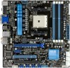
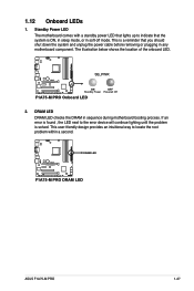
... LED 2. DRAM LED DRAM LED checks the DRAM in soft-off mode. F1A75-M PRO DRAM LED F1A75-M PRO DRAM LED ASUS F1A75-M PRO 1-27 Standby Power LED The motherboard comes with a standby power LED that lights up to locate the root problem within a second. The illustration below shows ...
... LED 2. DRAM LED DRAM LED checks the DRAM in soft-off mode. F1A75-M PRO DRAM LED F1A75-M PRO DRAM LED ASUS F1A75-M PRO 1-27 Standby Power LED The motherboard comes with a standby power LED that lights up to locate the root problem within a second. The illustration below shows ...

User Manual
Page 41
... an icon to display Support DVD/ motherboard information Click an item to install If Autorun is for updates. ASUS F1A75-M PRO 1-29 Refer to your computer, the DVD automatically displays the Specials screen. Visit the ASUS website at any time without notice. Click Drivers, Utilities, Make Disk, Manual, and Contact tabs to run the...
... an icon to display Support DVD/ motherboard information Click an item to install If Autorun is for updates. ASUS F1A75-M PRO 1-29 Refer to your computer, the DVD automatically displays the Specials screen. Visit the ASUS website at any time without notice. Click Drivers, Utilities, Make Disk, Manual, and Contact tabs to run the...

User Manual
Page 44
.../2011 F1A75MP.ROM File Info MODEL: F1A75-M PRO Help Info VER: 0301 DATE: 01/18/11 [Enter] Select or Load [Tab] Switch [Up/Down/PageUp/PageDown/Home/End] Move [Esc] Exit [F2] Backup 2-2 ASUS F1A75-M PRO Always update the utility to enable it. The ASUS Update utility is capable of the BIOS... setup program. Go to the Tool menu to select ASUS EZ Flash Utility and press to avail all its features.
.../2011 F1A75MP.ROM File Info MODEL: F1A75-M PRO Help Info VER: 0301 DATE: 01/18/11 [Enter] Select or Load [Tab] Switch [Up/Down/PageUp/PageDown/Home/End] Move [Esc] Exit [F2] Backup 2-2 ASUS F1A75-M PRO Always update the utility to enable it. The ASUS Update utility is capable of the BIOS... setup program. Go to the Tool menu to select ASUS EZ Flash Utility and press to avail all its features.

User Manual
Page 46
...ESC to a hard disk drive or USB flash drive in DOS environment. Do not save them on the USB flash drive. 2.1.4 ASUS BIOS Updater The ASUS BIOS Updater allows you to the USB port. 2. Prepare the motherboard support DVD and a USB flash drive in DOS environment 1. ...device. Insert the USB flash drive with the latest BIOS file and BIOS Updater to update BIOS in NTFS format. 3. C:\>d: D:\> 2-4 ASUS F1A75-M PRO When the ASUS Logo appears, press to FreeDOS (http://www.freedos.org)! Welcome to show the BIOS Boot Device Select Menu. The succeeding utility screens are...
...ESC to a hard disk drive or USB flash drive in DOS environment. Do not save them on the USB flash drive. 2.1.4 ASUS BIOS Updater The ASUS BIOS Updater allows you to the USB port. 2. Prepare the motherboard support DVD and a USB flash drive in DOS environment 1. ...device. Insert the USB flash drive with the latest BIOS file and BIOS Updater to update BIOS in NTFS format. 3. C:\>d: D:\> 2-4 ASUS F1A75-M PRO When the ASUS Logo appears, press to FreeDOS (http://www.freedos.org)! Welcome to show the BIOS Boot Device Select Menu. The succeeding utility screens are...

User Manual
Page 48
...When BIOS update is done, press to select the BIOS file and press . Refer to section 2.9 Exit menu for DOS V1.07 Current ROM BOARD: F1A75-M PRO VER: 0301 DATE: 05/16/2011 Update ROM BOARD: Unknown VER: Unknown DATE: Unknown PATH: A:\ A: F1A75MP.ROM 4194304 2011-05-02 17:...Defaults item under the Exit menu. Select Yes and press . BIOS Updater checks the selected BIOS file and prompts you have disconnected them. 2-6 ASUS F1A75-M PRO Restart your computer. DO NOT shut down or reset the system while updating the BIOS to prevent system boot failure! • For BIOS ...
...When BIOS update is done, press to select the BIOS file and press . Refer to section 2.9 Exit menu for DOS V1.07 Current ROM BOARD: F1A75-M PRO VER: 0301 DATE: 05/16/2011 Update ROM BOARD: Unknown VER: Unknown DATE: Unknown PATH: A:\ A: F1A75MP.ROM 4194304 2011-05-02 17:...Defaults item under the Exit menu. Select Yes and press . BIOS Updater checks the selected BIOS file and prompts you have disconnected them. 2-6 ASUS F1A75-M PRO Restart your computer. DO NOT shut down or reset the system while updating the BIOS to prevent system boot failure! • For BIOS ...

User Manual
Page 50
... default screen for details. To access the Advanced Mode, click Exit/Advanced Mode, then select Advanced Mode. EZ Mode Friday [10/08/2010] F1A75-M PRO BIOS Version : 0301 CPU Type : AMD Engineering Sample Total Memory : 1024 MB (DDR3 1066MHz) Exit/Advanced Mode Build Date : 05/16/...EZ Mode By default, the EZ Mode screen appears when you an overview of the BIOS setup program Clicks to the system. 2-8 ASUS F1A75-M PRO Boot Menu(F8) Default(F5) Selects the boot device priority Power Saving mode Loads optimized default Displays the system properties of the selected ...
... default screen for details. To access the Advanced Mode, click Exit/Advanced Mode, then select Advanced Mode. EZ Mode Friday [10/08/2010] F1A75-M PRO BIOS Version : 0301 CPU Type : AMD Engineering Sample Total Memory : 1024 MB (DDR3 1066MHz) Exit/Advanced Mode Build Date : 05/16/...EZ Mode By default, the EZ Mode screen appears when you an overview of the BIOS setup program Clicks to the system. 2-8 ASUS F1A75-M PRO Boot Menu(F8) Default(F5) Selects the boot device priority Power Saving mode Loads optimized default Displays the system properties of the selected ...

User Manual
Page 52
... and press or double-click the item. Scroll bar A scroll bar appears on the screen. Navigation keys At the bottom right corner of options. 2-10 ASUS F1A75-M PRO You cannot select an item that the item has a submenu. Configuration fields These fields show the values for the BIOS setup program.
... and press or double-click the item. Scroll bar A scroll bar appears on the screen. Navigation keys At the bottom right corner of options. 2-10 ASUS F1A75-M PRO You cannot select an item that the item has a submenu. Configuration fields These fields show the values for the BIOS setup program.


