User Manual
Page 13
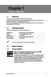
... a host of the items is damaged or missing, contact your motherboard package for buying an ASUS® F1A55-V PLUS motherboard! Before you for the following items. Motherboard Cables Accessories Application DVD Documentations ASUS F1A55-V PLUS motherboard 2 x Serial ATA 3.0Gb/s cables 1 x I/O shield ASUS motherboard Support DVD User Manual If any of new features and latest technologies, making it...
... a host of the items is damaged or missing, contact your motherboard package for buying an ASUS® F1A55-V PLUS motherboard! Before you for the following items. Motherboard Cables Accessories Application DVD Documentations ASUS F1A55-V PLUS motherboard 2 x Serial ATA 3.0Gb/s cables 1 x I/O shield ASUS motherboard Support DVD User Manual If any of new features and latest technologies, making it...

User Manual
Page 15
...Energy-related Products (ErP) ready, and ErP requires products to meet certain energy efficiency requirements in line with no need to energy consumptions. ASUS F1A55-V PLUS 1-3 C.P.R. (CPU Parameter Recall) The BIOS C.P.R. eliminates the need to their default settings. ErP ready The motherboard is a user-friendly ...using a bootable floppy disk or an OS-based utility. This is an auto-recovery tool that contains the BIOS file. ASUS CrashFree BIOS 3 ASUS CrashFree BIOS 3 is in regards to open the system chassis and clear the RTC data. AI Suite II With its fast...
...Energy-related Products (ErP) ready, and ErP requires products to meet certain energy efficiency requirements in line with no need to energy consumptions. ASUS F1A55-V PLUS 1-3 C.P.R. (CPU Parameter Recall) The BIOS C.P.R. eliminates the need to their default settings. ErP ready The motherboard is a user-friendly ...using a bootable floppy disk or an OS-based utility. This is an auto-recovery tool that contains the BIOS file. ASUS CrashFree BIOS 3 ASUS CrashFree BIOS 3 is in regards to open the system chassis and clear the RTC data. AI Suite II With its fast...
User Manual
Page 17
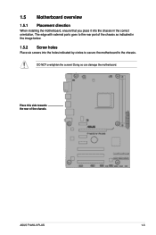
1.5 Motherboard overview 1.5.1 Placement direction When installing the motherboard, ensure that you place it into the holes indicated by circles to secure the motherboard to the rear part of the chassis. ASUS F1A55-V PLUS 1-5 The edge with external ports goes to the chassis. DO NOT overtighten the screws! Place this side towards the rear of the chassis as indicated in the image below. 1.5.2 Screw holes Place six screws into the chassis in the correct orientation. Doing so can damage the motherboard.
1.5 Motherboard overview 1.5.1 Placement direction When installing the motherboard, ensure that you place it into the holes indicated by circles to secure the motherboard to the rear part of the chassis. ASUS F1A55-V PLUS 1-5 The edge with external ports goes to the chassis. DO NOT overtighten the screws! Place this side towards the rear of the chassis as indicated in the image below. 1.5.2 Screw holes Place six screws into the chassis in the correct orientation. Doing so can damage the motherboard.
User Manual
Page 19
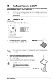
... with the gold triangle matches the socket corner with a small triangle. 4. otherwise, the APU will not fit in one correct orientation. Small triangle Gold triangle ASUS F1A55-V PLUS 1-7 Position the APU above the socket such that the socket lever is lifted up to prevent bending the pins and damaging the APU! 1.6.1 Installing the...
... with the gold triangle matches the socket corner with a small triangle. 4. otherwise, the APU will not fit in one correct orientation. Small triangle Gold triangle ASUS F1A55-V PLUS 1-7 Position the APU above the socket such that the socket lever is lifted up to prevent bending the pins and damaging the APU! 1.6.1 Installing the...
User Manual
Page 21
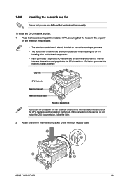
Place the heatsink on top of the retention bracket to the retention module base. 1 2 3 4 5 ASUS F1A55-V PLUS 1-9 CPU Fan CPU Heatsink Retention bracket Retention Module Base Retention bracket lock Your boxed CPU heatsink and fan assembly should come with installation instructions for ...
Place the heatsink on top of the retention bracket to the retention module base. 1 2 3 4 5 ASUS F1A55-V PLUS 1-9 CPU Fan CPU Heatsink Retention bracket Retention Module Base Retention bracket lock Your boxed CPU heatsink and fan assembly should come with installation instructions for ...

User Manual
Page 23
...for the OS can be about 3GB or less. ASUS F1A55-V PLUS 1-11 Use a 64-bit Windows® OS if you obtain memory modules from the blue slots for better overclocking capability. • Always install DIMMs with 8GB or above DIMMs. ASUS will update the memory QVL once the DIMMs are... 1866 MHz or higher frequency DIMMs. • Due to support a full memory load (2 DIMMs) or overclocking condition. • Visit the ASUS website at www.asus.com for overclocking may operate at a lower frequency than the vendor-marked value. • For system stability, use of memory, we recommend...
...for the OS can be about 3GB or less. ASUS F1A55-V PLUS 1-11 Use a 64-bit Windows® OS if you obtain memory modules from the blue slots for better overclocking capability. • Always install DIMMs with 8GB or above DIMMs. ASUS will update the memory QVL once the DIMMs are... 1866 MHz or higher frequency DIMMs. • Due to support a full memory load (2 DIMMs) or overclocking condition. • Visit the ASUS website at www.asus.com for overclocking may operate at a lower frequency than the vendor-marked value. • For system stability, use of memory, we recommend...
User Manual
Page 29
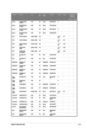
... DS Micron 9GF27D9KPT - - • • 1GB SS Micron 8FD22D9JNM - - • • 2GB SS Elixir N2CB2G80D - - • • N-CG 4GB DS Elixir N2CB2G80B - - • • N-CG ASUS F1A55-V PLUS 1-17 Vendors Part No. Micron Micron Micron Micron OCZ MT8JTF12864A Z-1G4F1 MT8JTF25664A Z-1G4D1 MT16JTF25664A Z-1G4F1 MT16JTF51264A Z-1G4D1 OCZ3F13334GK OCZ OCZ3P13334GK OCZ OCZ OCZ PSC PSC...
... DS Micron 9GF27D9KPT - - • • 1GB SS Micron 8FD22D9JNM - - • • 2GB SS Elixir N2CB2G80D - - • • N-CG 4GB DS Elixir N2CB2G80B - - • • N-CG ASUS F1A55-V PLUS 1-17 Vendors Part No. Micron Micron Micron Micron OCZ MT8JTF12864A Z-1G4F1 MT8JTF25664A Z-1G4D1 MT16JTF25664A Z-1G4F1 MT16JTF51264A Z-1G4D1 OCZ3F13334GK OCZ OCZ3P13334GK OCZ OCZ OCZ PSC PSC...

User Manual
Page 33
... bracket opposite the slot that complies with the screw you physical injury and damage motherboard components. 1.8.1 Installing an expansion card To install an expansion card: 1. ASUS F1A55-V PLUS 1-21 Failure to use . 4. Keep the screw for information on shared slots, ensure that the drivers support "Share IRQ" or that they support. Secure the...
... bracket opposite the slot that complies with the screw you physical injury and damage motherboard components. 1.8.1 Installing an expansion card To install an expansion card: 1. ASUS F1A55-V PLUS 1-21 Failure to use . 4. Keep the screw for information on shared slots, ensure that the drivers support "Share IRQ" or that they support. Secure the...
User Manual
Page 35
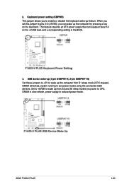
... running in the BIOS. 3. USB device wake-up feature. 2. Keyboard power setting (KBPWR) This jumper allows you can supply at least 1A on the keyboard. ASUS F1A55-V PLUS 1-23 Set to +5VSB to wake up the computer by pressing a key on the +5VSB lead, and a corresponding setting in low power mode) using the...
... running in the BIOS. 3. USB device wake-up feature. 2. Keyboard power setting (KBPWR) This jumper allows you can supply at least 1A on the keyboard. ASUS F1A55-V PLUS 1-23 Set to +5VSB to wake up the computer by pressing a key on the +5VSB lead, and a corresponding setting in low power mode) using the...
User Manual
Page 37
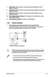
..., ensuring that the black wire of each cable matches the ground pin of maximum 2A (24 W) fan power. • Only the CPU_FAN connector supports the ASUS Fan Xpert feature. • If you install two VGA cards, we recommend that you plug the rear chassis fan cable to the fan connectors. These... other VGA-compatible devices. 11. USB 2.0 ports 5 and 6. This 15-pin port is for USB USB 2.0/1.1 devices. 9. These are for a PS/2 keyboard. 1.10.2 Internal connectors 1. ASUS F1A55-V PLUS 1-25
..., ensuring that the black wire of each cable matches the ground pin of maximum 2A (24 W) fan power. • Only the CPU_FAN connector supports the ASUS Fan Xpert feature. • If you install two VGA cards, we recommend that you plug the rear chassis fan cable to the fan connectors. These... other VGA-compatible devices. 11. USB 2.0 ports 5 and 6. This 15-pin port is for USB USB 2.0/1.1 devices. 9. These are for a PS/2 keyboard. 1.10.2 Internal connectors 1. ASUS F1A55-V PLUS 1-25

User Manual
Page 39
... cables for a chassis-mounted intrusion detection sensor or switch. The Serial ATA RAID feature is for Serial ATA hard disk drives and optical disc drives. ASUS F1A55-V PLUS 1-27 The signal is removed or replaced. 4. Serial ATA 3.0 Gb/s connectors (7-pin SATA3G 1~6) These connectors are set the type of the chassis intrusion sensor or...
... cables for a chassis-mounted intrusion detection sensor or switch. The Serial ATA RAID feature is for Serial ATA hard disk drives and optical disc drives. ASUS F1A55-V PLUS 1-27 The signal is removed or replaced. 4. Serial ATA 3.0 Gb/s connectors (7-pin SATA3G 1~6) These connectors are set the type of the chassis intrusion sensor or...
User Manual
Page 41
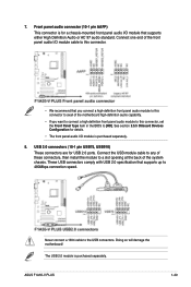
... are for a chassis-mounted front panel audio I /O module is purchased separately. Never connect a 1394 cable to a slot opening at the back of the system chassis. ASUS F1A55-V PLUS 1-29 Connect the USB module cable to any of the motherboard high-definition audio capability. • If you want to connect a high definition front panel...
... are for a chassis-mounted front panel audio I /O module is purchased separately. Never connect a 1394 cable to a slot opening at the back of the system chassis. ASUS F1A55-V PLUS 1-29 Connect the USB module cable to any of the motherboard high-definition audio capability. • If you want to connect a high definition front panel...

User Manual
Page 44
... Info VER: 0211 DATE: 07/28/11 [Enter] Select or Load [Tab] Switch [Up/Down/PageUp/PageDown/Home/End] Move [Esc] Exit [F2] Backup 2-2 ASUS F1A55-V PLUS The ASUS Update utility is capable of the BIOS setup program. To update the BIOS using this utility, download the latest BIOS file from a BIOS file a. Always...
... Info VER: 0211 DATE: 07/28/11 [Enter] Select or Load [Tab] Switch [Up/Down/PageUp/PageDown/Home/End] Move [Esc] Exit [F2] Backup 2-2 ASUS F1A55-V PLUS The ASUS Update utility is capable of the BIOS setup program. To update the BIOS using this utility, download the latest BIOS file from a BIOS file a. Always...

User Manual
Page 46
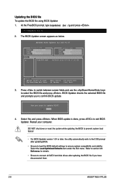
...Do not save them on the USB flash drive. At the FreeDOS prompt, type d: and press to switch the disk from the ASUS website at http://support.asus.com and save the BIOS file and BIOS Updater to a hard disk drive or USB flash drive in FAT32/16 format and ... when the BIOS fails or gets corrupted during the updating process. Turn off the computer and disconnect all SATA hard disk drives (optional). C:\>d: D:\> 2-4 ASUS F1A55-V PLUS The actual utility screen displays may not be same as the boot device. Booting the system in DOS environment. Boot your computer. When the Make...
...Do not save them on the USB flash drive. At the FreeDOS prompt, type d: and press to switch the disk from the ASUS website at http://support.asus.com and save the BIOS file and BIOS Updater to a hard disk drive or USB flash drive in FAT32/16 format and ... when the BIOS fails or gets corrupted during the updating process. Turn off the computer and disconnect all SATA hard disk drives (optional). C:\>d: D:\> 2-4 ASUS F1A55-V PLUS The actual utility screen displays may not be same as the boot device. Booting the system in DOS environment. Boot your computer. When the Make...
User Manual
Page 48
... No 4. The BIOS Updater screen appears as below. Are you to the DOS prompt after updating the BIOS file if you have disconnected them. 2-6 ASUS F1A55-V PLUS DO NOT shut down or reset the system while updating the BIOS to prevent system boot failure! • For BIOS Updater version 1.04 or later...updating BIOS. • Ensure to load the BIOS default settings to update BIOS? Refer to section 2.9 Exit menu for DOS V1.07 Current ROM BOARD: F1A55-V PLUS VER: 0211 DATE: 07/28/2011 Update ROM BOARD: Unknown VER: Unknown DATE: Unknown PATH: A:\ A: F1A55VP.ROM 4194304 2011-07-28 17:30:...
... No 4. The BIOS Updater screen appears as below. Are you to the DOS prompt after updating the BIOS file if you have disconnected them. 2-6 ASUS F1A55-V PLUS DO NOT shut down or reset the system while updating the BIOS to prevent system boot failure! • For BIOS Updater version 1.04 or later...updating BIOS. • Ensure to load the BIOS default settings to update BIOS? Refer to section 2.9 Exit menu for DOS V1.07 Current ROM BOARD: F1A55-V PLUS VER: 0211 DATE: 07/28/2011 Update ROM BOARD: Unknown VER: Unknown DATE: Unknown PATH: A:\ A: F1A55VP.ROM 4194304 2011-07-28 17:30:...
User Manual
Page 50
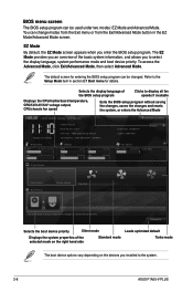
...the BIOS setup program. EZ Mode By default, the EZ Mode screen appears when you installed to decide the boot priority. EZ Mode Tuesday [1/1/2008] F1A55-V PLUS BIOS Version : 0211 CPU Type : AMD Engineering Sample Total Memory : 1024 MB (DDR3 1333MHz) Exit/Advanced Mode Build Date : 07/28/2011 ...12.248V Q-Fan Control Quiet Performance Boot Priority Energy Saving Standard Use the mouse to drag or keyboard to navigate to the system. 2-8 ASUS F1A55-V PLUS BIOS menu screen The BIOS setup program can be used under two modes: EZ Mode and Advanced Mode. You can change modes from the ...
...the BIOS setup program. EZ Mode By default, the EZ Mode screen appears when you installed to decide the boot priority. EZ Mode Tuesday [1/1/2008] F1A55-V PLUS BIOS Version : 0211 CPU Type : AMD Engineering Sample Total Memory : 1024 MB (DDR3 1333MHz) Exit/Advanced Mode Build Date : 07/28/2011 ...12.248V Q-Fan Control Quiet Performance Boot Priority Energy Saving Standard Use the mouse to drag or keyboard to navigate to the system. 2-8 ASUS F1A55-V PLUS BIOS menu screen The BIOS setup program can be used under two modes: EZ Mode and Advanced Mode. You can change modes from the ...
User Manual
Page 52
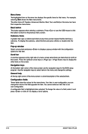
... navigation keys to display a pop-up window Select a menu item and press to select items in the menu and change the value of options. 2-10 ASUS F1A55-V PLUS To change the settings. Press the Up/Down arrow keys or / keys to display a list of a field, select it and press or click on it...
... navigation keys to display a pop-up window Select a menu item and press to select items in the menu and change the value of options. 2-10 ASUS F1A55-V PLUS To change the settings. Press the Up/Down arrow keys or / keys to display a list of a field, select it and press or click on it...
User Manual
Page 54
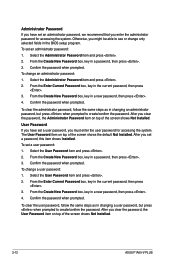
... the screen shows the default Not Installed. To set an administrator password: 1. The User Password item on top of the screen shows Not Installed. 2-12 ASUS F1A55-V PLUS To change a user password: 1.
... the screen shows the default Not Installed. To set an administrator password: 1. The User Password item on top of the screen shows Not Installed. 2-12 ASUS F1A55-V PLUS To change a user password: 1.
User Manual
Page 56
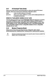
...-2000MHz 9-99-24 1.65V] [DDR3-2133MHz 9-9-9-24 1.65V] [DDR3-2200MHz 9-9-9-24 1.65V] [DDR32400MHz 9-9-9-24 1.65V] 2.4.2 Memory Frequency [Auto] Allows you to the default setting. 2-14 ASUS F1A55-V PLUS profile, and the related parameters will be adjusted automatically.
...-2000MHz 9-99-24 1.65V] [DDR3-2133MHz 9-9-9-24 1.65V] [DDR3-2200MHz 9-9-9-24 1.65V] [DDR32400MHz 9-9-9-24 1.65V] 2.4.2 Memory Frequency [Auto] Allows you to the default setting. 2-14 ASUS F1A55-V PLUS profile, and the related parameters will be adjusted automatically.
User Manual
Page 58
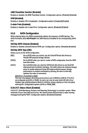
... SATA Type [IDE] Allows you to set to internally optimize the order of commands. Configuration options: [AHCI or RAID] [IDE] S.M.A.R.T. Configuration options: [Enabled] [Disabled] 2-16 ASUS F1A55-V PLUS Configuration options: [Enabled] [Disabled] SVM [Enabled] Enables or disables CPU virtualization. SATA Port 5 - Set to [IDE] instead of [AHCI or RAID] to access devices on...
... SATA Type [IDE] Allows you to set to internally optimize the order of commands. Configuration options: [AHCI or RAID] [IDE] S.M.A.R.T. Configuration options: [Enabled] [Disabled] 2-16 ASUS F1A55-V PLUS Configuration options: [Enabled] [Disabled] SVM [Enabled] Enables or disables CPU virtualization. SATA Port 5 - Set to [IDE] instead of [AHCI or RAID] to access devices on...

