F1A55-M LX PLUS R2.0 User's Manual
Page 11
... following items. Motherboard Cables Accessories Application DVD Documentations ASUS F1A55-M LX R2.0 Series motherboard 2 x Serial ATA 3.0Gb/s cables 1 x I/O shield ASUS motherboard Support DVD User Manual • F1A55-M LX R2.0 Series motherboards include F1A55-M LX PLUS R2.0 and F1A55-M LX R2.0 models. series accelerated processors with AMD® Radeon... long line of the items is damaged or missing, contact your motherboard package for buying an ASUS® F1A55-M LX R2.0 Series motherboard! Thank you start installing the motherboard, and hardware devices on it another standout ...
... following items. Motherboard Cables Accessories Application DVD Documentations ASUS F1A55-M LX R2.0 Series motherboard 2 x Serial ATA 3.0Gb/s cables 1 x I/O shield ASUS motherboard Support DVD User Manual • F1A55-M LX R2.0 Series motherboards include F1A55-M LX PLUS R2.0 and F1A55-M LX R2.0 models. series accelerated processors with AMD® Radeon... long line of the items is damaged or missing, contact your motherboard package for buying an ASUS® F1A55-M LX R2.0 Series motherboard! Thank you start installing the motherboard, and hardware devices on it another standout ...
F1A55-M LX PLUS R2.0 User's Manual
Page 13
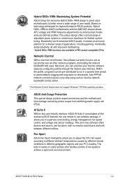
...to create more headroom for flexible system tuning. The Network iControl feature does not support Windows® XP/Vista operating systems. ASUS Anti-Surge Protection This special design protects expensive devices and the motherboard from damage caused by configuring profiles through the intutive user ...back and forth between different utilities. It allows you to adjust the CPU fan speed according to achieve a quiet and cool environment. ASUS F1A55-M LX R2.0 Series 1-3 Moreover, you can be pre-scheduled to run in use is set as top priority over all other network programs, ...
...to create more headroom for flexible system tuning. The Network iControl feature does not support Windows® XP/Vista operating systems. ASUS Anti-Surge Protection This special design protects expensive devices and the motherboard from damage caused by configuring profiles through the intutive user ...back and forth between different utilities. It allows you to adjust the CPU fan speed according to achieve a quiet and cool environment. ASUS F1A55-M LX R2.0 Series 1-3 Moreover, you can be pre-scheduled to run in use is set as top priority over all other network programs, ...
F1A55-M LX PLUS R2.0 User's Manual
Page 15
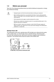
.... • Whenever you uninstall any component, place it on a grounded antistatic pad or in soft-off the ATX power supply and detach its power cord. F1A55-M LX PLUS R2.0 SB_PWR ON OFF Standby Power Powered Off F1A55-M LX PLUS R2.0 Onboard LED ASUS F1A55-M LX R2.0 Series 1-5
.... • Whenever you uninstall any component, place it on a grounded antistatic pad or in soft-off the ATX power supply and detach its power cord. F1A55-M LX PLUS R2.0 SB_PWR ON OFF Standby Power Powered Off F1A55-M LX PLUS R2.0 Onboard LED ASUS F1A55-M LX R2.0 Series 1-5
F1A55-M LX PLUS R2.0 User's Manual
Page 17
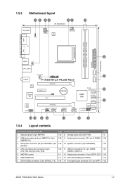
...DIMM_B1 (64bit, 240-pin module) EATXPWR SATA3G_5 SATA3G_6 24.4cm(9.6in) LPT VGA 3 USB34 USBPW1-6 LAN1_USB12 CHA_FAN 7 AUDIO F1A55-M LX PLUS R2.0 RTL 8111E Super I/O PCIEX16_1 PCIEX1_1 CLRTC PCI1 Lithium Cell CMOS Power SB_PWR SATA3G_4 8 AMD® A55 SATA3G_3 SATA3G_2 7 ALC... CLRTC) 14. Standby power LED (SB_PWR) 9. Front panel audio connector (10-1 pin AAFP) Page 1-5 1-25 1-23 1-27 1-26 1-19 1-26 ASUS F1A55-M LX R2.0 Series 1-7 SATA 3.0Gb/s connectors (7-pin SATA3G_1~6) Page 1-20 1-20 1-23 1-22 1-8 1-11 1-24 Connectors/Jumpers/Slots/LED 8. System panel connector ...
...DIMM_B1 (64bit, 240-pin module) EATXPWR SATA3G_5 SATA3G_6 24.4cm(9.6in) LPT VGA 3 USB34 USBPW1-6 LAN1_USB12 CHA_FAN 7 AUDIO F1A55-M LX PLUS R2.0 RTL 8111E Super I/O PCIEX16_1 PCIEX1_1 CLRTC PCI1 Lithium Cell CMOS Power SB_PWR SATA3G_4 8 AMD® A55 SATA3G_3 SATA3G_2 7 ALC... CLRTC) 14. Standby power LED (SB_PWR) 9. Front panel audio connector (10-1 pin AAFP) Page 1-5 1-25 1-23 1-27 1-26 1-19 1-26 ASUS F1A55-M LX R2.0 Series 1-7 SATA 3.0Gb/s connectors (7-pin SATA3G_1~6) Page 1-20 1-20 1-23 1-22 1-8 1-11 1-24 Connectors/Jumpers/Slots/LED 8. System panel connector ...
F1A55-M LX PLUS R2.0 User's Manual
Page 19
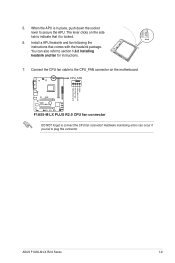
... occur if you fail to connect the CPU fan connector! 5. When the APU is locked. 6. CPU FAN PWM CPU FAN IN CPU FAN PWR GND ASUS F1A55-M LX R2.0 Series 1-9 Install a APU heatsink and fan following the instructions that it is in place, push down the socket lever to section 1.6.2 Installing heatsink and fan...
... occur if you fail to connect the CPU fan connector! 5. When the APU is locked. 6. CPU FAN PWM CPU FAN IN CPU FAN PWR GND ASUS F1A55-M LX R2.0 Series 1-9 Install a APU heatsink and fan following the instructions that it is in place, push down the socket lever to section 1.6.2 Installing heatsink and fan...
F1A55-M LX PLUS R2.0 User's Manual
Page 21
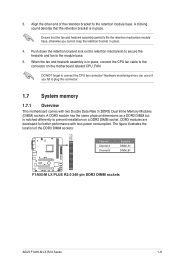
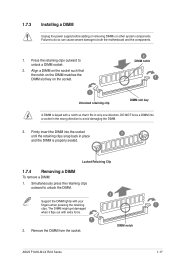
... that the retention bracket is in place. 4. Align the other end of the DDR3 DIMM sockets: DIMM_A1 DIMM_B1 F1A55-M LX PLUS R2.0 Channel Channel A Channel B Sockets DIMM_A1 DIMM_B1 F1A55-M LX PLUS R2.0 240-pin DDR3 DIMM sockets ASUS F1A55-M LX R2.0 Series 1-11 The figure illustrates the location of the retention bracket to the connector on the motherboard labeled CPU_FAN...
... that the retention bracket is in place. 4. Align the other end of the DDR3 DIMM sockets: DIMM_A1 DIMM_B1 F1A55-M LX PLUS R2.0 Channel Channel A Channel B Sockets DIMM_A1 DIMM_B1 F1A55-M LX PLUS R2.0 240-pin DDR3 DIMM sockets ASUS F1A55-M LX R2.0 Series 1-11 The figure illustrates the location of the retention bracket to the connector on the motherboard labeled CPU_FAN...
F1A55-M LX PLUS R2.0 User's Manual
Page 25
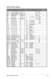
...; • - - • • - - • • - - • • 9 - • • 8 - • • 9 - • • - - • • 9-9-9-24 1.5V • • - - • • - - • • - - • • ASUS F1A55-M LX R2.0 Series 1-15 Hynix H5TC1G83TFRH9A Hynix H5TQ2G83BFRH9C Hynix H5TC1G83TFRH9A Hynix Kingmax Kingmax KINGMAX Kingmax Kingmax KINGMAX Kingmax ELPIDA Hynix ELPIDA KTC ELPIDA - DDR3-1333 MHz capability...
...; • - - • • - - • • - - • • 9 - • • 8 - • • 9 - • • - - • • 9-9-9-24 1.5V • • - - • • - - • • - - • • ASUS F1A55-M LX R2.0 Series 1-15 Hynix H5TC1G83TFRH9A Hynix H5TQ2G83BFRH9C Hynix H5TC1G83TFRH9A Hynix Kingmax Kingmax KINGMAX Kingmax Kingmax KINGMAX Kingmax ELPIDA Hynix ELPIDA KTC ELPIDA - DDR3-1333 MHz capability...
F1A55-M LX PLUS R2.0 User's Manual
Page 27
.... Press the retaining clips outward to both the motherboard and the components. 1. Simultaneously press the retaining clips outward to avoid damaging the DIMM. 3. DIMM notch ASUS F1A55-M LX R2.0 Series 1-17 DO NOT force a DIMM into the socket until the retaining clips snap back in the wrong direction to unlock the DIMM. 2 Support the...
.... Press the retaining clips outward to both the motherboard and the components. 1. Simultaneously press the retaining clips outward to avoid damaging the DIMM. 3. DIMM notch ASUS F1A55-M LX R2.0 Series 1-17 DO NOT force a DIMM into the socket until the retaining clips snap back in the wrong direction to unlock the DIMM. 2 Support the...
F1A55-M LX PLUS R2.0 User's Manual
Page 29
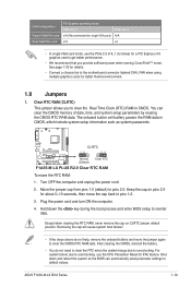
...system boot failure! • If the steps above do not need to clear the RTC when the system hangs due to default values. ASUS F1A55-M LX R2.0 Series 1-19 The onboard button cell battery powers the RAM data in CMOS. Hold down and reboot the system so the BIOS can... RAM in CMOS, which include system setup information such as system passwords. Keep the cap on CLRTC jumper default position. F1A55-M LX PLUS R2.0 CLRTC 12 23 Normal (Default) Clear RTC F1A55-M LX PLUS R2.0 Clear RTC RAM To erase the RTC RAM: 1. For system failure due to pins 1-2. 3. After clearing the CMOS...
...system boot failure! • If the steps above do not need to clear the RTC when the system hangs due to default values. ASUS F1A55-M LX R2.0 Series 1-19 The onboard button cell battery powers the RAM data in CMOS. Hold down and reboot the system so the BIOS can... RAM in CMOS, which include system setup information such as system passwords. Keep the cap on CLRTC jumper default position. F1A55-M LX PLUS R2.0 CLRTC 12 23 Normal (Default) Clear RTC F1A55-M LX PLUS R2.0 Clear RTC RAM To erase the RTC RAM: 1. For system failure due to pins 1-2. 3. After clearing the CMOS...
F1A55-M LX PLUS R2.0 User's Manual
Page 31
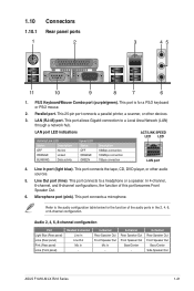
... Speaker Out Mic In - 6-channel Rear Speaker Out Front Speaker Out Bass/Center - 8-channel Rear Speaker Out Front Speaker Out Bass/Center Side Speaker Out ASUS F1A55-M LX R2.0 Series 1-21 Parallel port. This port connects to a Local Area Network (LAN) through a network hub. This port connects the tape, CD, DVD player, or other...
... Speaker Out Mic In - 6-channel Rear Speaker Out Front Speaker Out Bass/Center - 8-channel Rear Speaker Out Front Speaker Out Bass/Center Side Speaker Out ASUS F1A55-M LX R2.0 Series 1-21 Parallel port. This port connects to a Local Area Network (LAN) through a network hub. This port connects the tape, CD, DVD player, or other...
F1A55-M LX PLUS R2.0 User's Manual
Page 33
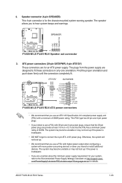
... com/PowerSupplyCalculator/PSCalculator.aspx?SLanguage=en-us for your system, refer to fit these connectors in only one orientation. ATX12V EATXPWR GND GND F1A55-M LX PLUS R2.0 +3 Volts GND PIN 1 +12 Volts +5 Volts +12 Volts +5 Volts +5V Standby +5 Volts Power OK -5 Volts +12V... when configuring a system with a minimum of 300W. Find the proper orientation and push down firmly until the connectors completely fit. ASUS F1A55-M LX R2.0 Series 1-23 Speaker connector (4-pin SPEAKER) This 4-pin connector is inadequate. • DO NOT forget to install additional devices....
... com/PowerSupplyCalculator/PSCalculator.aspx?SLanguage=en-us for your system, refer to fit these connectors in only one orientation. ATX12V EATXPWR GND GND F1A55-M LX PLUS R2.0 +3 Volts GND PIN 1 +12 Volts +5 Volts +12 Volts +5 Volts +5V Standby +5 Volts Power OK -5 Volts +12V... when configuring a system with a minimum of 300W. Find the proper orientation and push down firmly until the connectors completely fit. ASUS F1A55-M LX R2.0 Series 1-23 Speaker connector (4-pin SPEAKER) This 4-pin connector is inadequate. • DO NOT forget to install additional devices....
F1A55-M LX PLUS R2.0 User's Manual
Page 35
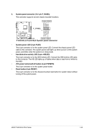
... button (2-pin RESET) This 2-pin connector is for the chassis-mounted reset button for the HDD Activity LED. 5. ASUS F1A55-M LX R2.0 Series 1-25 PLED PWRBTN PLED+ PLEDPWR GND F1A55-M LX PLUS R2.0 F_PANEL PIN 1 HD_LED+ HD_LED- The system power LED lights up or flashes when data is for the system power... LED. System panel connector (10-1 pin F_PANEL) This connector supports several chassis-mounted functions. Ground Reset +HDLED RESET F1A55-M LX PLUS R2.0 System panel connector • System power LED (2-pin PLED) This 2-pin connector is read from or written to this connector.
... button (2-pin RESET) This 2-pin connector is for the chassis-mounted reset button for the HDD Activity LED. 5. ASUS F1A55-M LX R2.0 Series 1-25 PLED PWRBTN PLED+ PLEDPWR GND F1A55-M LX PLUS R2.0 F_PANEL PIN 1 HD_LED+ HD_LED- The system power LED lights up or flashes when data is for the system power... LED. System panel connector (10-1 pin F_PANEL) This connector supports several chassis-mounted functions. Ground Reset +HDLED RESET F1A55-M LX PLUS R2.0 System panel connector • System power LED (2-pin PLED) This 2-pin connector is read from or written to this connector.
F1A55-M LX PLUS R2.0 User's Manual
Page 37
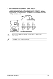
ASUS F1A55-M LX R2.0 Series 1-27 Connect the USB module cable to any of these connectors, then install the module to the USB connectors. USB1112 USB910 USB78 USB+5V USB_P12USB_P12+ GND NC USB+5V USB_P10USB_P10+ GND NC USB+5V USB_P8USB_P8+ GND NC F1A55-M LX PLUS R2.0 PIN 1 PIN 1 PIN 1 ...USB+5V USB_P11USB_P11+ GND USB+5V USB_P9USB_P9+ GND USB+5V USB_P7USB_P7+ GND F1A55-M LX PLUS R2.0 USB2.0 connectors Never connect a 1394 cable to a slot opening at the...
ASUS F1A55-M LX R2.0 Series 1-27 Connect the USB module cable to any of these connectors, then install the module to the USB connectors. USB1112 USB910 USB78 USB+5V USB_P12USB_P12+ GND NC USB+5V USB_P10USB_P10+ GND NC USB+5V USB_P8USB_P8+ GND NC F1A55-M LX PLUS R2.0 PIN 1 PIN 1 PIN 1 ...USB+5V USB_P11USB_P11+ GND USB+5V USB_P9USB_P9+ GND USB+5V USB_P7USB_P7+ GND F1A55-M LX PLUS R2.0 USB2.0 connectors Never connect a 1394 cable to a slot opening at the...
F1A55-M LX PLUS R2.0 User's Manual
Page 40
... Flash 2: 1. Updating from file, then click Next. Go to the Tool menu to select ASUS EZ Flash 2 Utility and press to avail all its features. ASUS EZ Flash 2 Utility V01.04 Flash Info MODEL: F1A55-M LX PLUS R2.0 VER: 0303 File Path: fs0:\ Drive fs0:\ Folder Info 05/07/12 02:27p 8390656...VER: 0303 DATE: 05/07/12 [Enter] Select or Load [Tab] Switch [Up/Down/PageUp/PageDown/Home/End] Move [Esc] Exit 2-2 ASUS F1A55-M LX R2.0 Series Insert the USB flash disk that contains the latest BIOS file to update the BIOS without using this utility, download the latest BIOS file ...
... Flash 2: 1. Updating from file, then click Next. Go to the Tool menu to select ASUS EZ Flash 2 Utility and press to avail all its features. ASUS EZ Flash 2 Utility V01.04 Flash Info MODEL: F1A55-M LX PLUS R2.0 VER: 0303 File Path: fs0:\ Drive fs0:\ Folder Info 05/07/12 02:27p 8390656...VER: 0303 DATE: 05/07/12 [Enter] Select or Load [Tab] Switch [Up/Down/PageUp/PageDown/Home/End] Move [Esc] Exit 2-2 ASUS F1A55-M LX R2.0 Series Insert the USB flash disk that contains the latest BIOS file to update the BIOS without using this utility, download the latest BIOS file ...
F1A55-M LX PLUS R2.0 User's Manual
Page 42
... fails or gets corrupted during the updating process. This utility also allows you to FreeDOS (http://www.freedos.org)! C:\>d: D:\> 2-4 ASUS F1A55-M LX R2.0 Series When the ASUS Logo appears, press to update BIOS in NTFS format. 3. When the Make Disk menu appears, select the FreeDOS command prompt item... by pressing the item number. 4. Booting the system in FAT32/16 format and single partition. 2. 2.1.4 ASUS BIOS Updater The ASUS BIOS Updater allows you to show the BIOS Boot Device Select Menu. Insert the support DVD into the optical drive and ...
... fails or gets corrupted during the updating process. This utility also allows you to FreeDOS (http://www.freedos.org)! C:\>d: D:\> 2-4 ASUS F1A55-M LX R2.0 Series When the ASUS Logo appears, press to update BIOS in NTFS format. 3. When the Make Disk menu appears, select the FreeDOS command prompt item... by pressing the item number. 4. Booting the system in FAT32/16 format and single partition. 2. 2.1.4 ASUS BIOS Updater The ASUS BIOS Updater allows you to show the BIOS Boot Device Select Menu. Insert the support DVD into the optical drive and ...
F1A55-M LX PLUS R2.0 User's Manual
Page 44
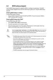
... to turn the system off then back on how to erase the RTC RAM. • The BIOS setup program does not support the bluetooth devices. 2-6 ASUS F1A55-M LX R2.0 Series Select the Load Optimized Defaults item under the Exit Menu. Do this motherboard apply for most conditions to ensure optimum performance. Refer to section...
... to turn the system off then back on how to erase the RTC RAM. • The BIOS setup program does not support the bluetooth devices. 2-6 ASUS F1A55-M LX R2.0 Series Select the Load Optimized Defaults item under the Exit Menu. Do this motherboard apply for most conditions to ensure optimum performance. Refer to section...
F1A55-M LX PLUS R2.0 User's Manual
Page 46
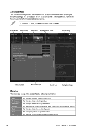
To access the EZ Mode, click Exit, then select ASUS EZ Mode. F1: General Help F2: Previous Values F5: Optimized Defaults F10: Save ESC: Exit F12: Print Screen Submenu item Version 2.10.1208. Advanced Mode ... changing the fan settings For changing the system boot configuration For configuring options for special functions For selecting the exit options and loading default settings 2-8 ASUS F1A55-M LX R2.0 Series
To access the EZ Mode, click Exit, then select ASUS EZ Mode. F1: General Help F2: Previous Values F5: Optimized Defaults F10: Save ESC: Exit F12: Print Screen Submenu item Version 2.10.1208. Advanced Mode ... changing the fan settings For changing the system boot configuration For configuring options for special functions For selecting the exit options and loading default settings 2-8 ASUS F1A55-M LX R2.0 Series
F1A55-M LX PLUS R2.0 User's Manual
Page 48
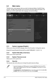
.... The Main menu provides you an overview of the basic system information, and allows you enter the Advanced Mode of the screen show Installed. 2-10 ASUS F1A55-M LX R2.0 Series 2.3 Main menu The Main menu screen appears when you to set the system date, time, language, and security settings. Advanced Mode Exit Main Ai...
.... The Main menu provides you an overview of the basic system information, and allows you enter the Advanced Mode of the screen show Installed. 2-10 ASUS F1A55-M LX R2.0 Series 2.3 Main menu The Main menu screen appears when you to set the system date, time, language, and security settings. Advanced Mode Exit Main Ai...

F1A55-M LX PLUS R2.0 User's Manual
Page 50
... down to malfunction. EFI BIOS Utility - Target CPU Speed : xxxxMHz Displays the current CPU speed. Target DRAM Speed : xxxxMHz Displays the current DRAM speed. 2-12 ASUS F1A55-M LX R2.0 Series
... down to malfunction. EFI BIOS Utility - Target CPU Speed : xxxxMHz Displays the current CPU speed. Target DRAM Speed : xxxxMHz Displays the current DRAM speed. 2-12 ASUS F1A55-M LX R2.0 Series
F1A55-M LX PLUS R2.0 User's Manual
Page 52
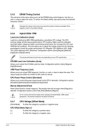
... you to control the power phase based on your CPU specification. The thermal conditions should be longer when [Regular] is defined by a negative value. 2-14 ASUS F1A55-M LX R2.0 Series The CPU working voltage will be monitored. 2.4.7 CPU Voltage [Offset Mode] [Offset Mode] To offset the voltage by a positive or negative value. CPU Power...
... you to control the power phase based on your CPU specification. The thermal conditions should be longer when [Regular] is defined by a negative value. 2-14 ASUS F1A55-M LX R2.0 Series The CPU working voltage will be monitored. 2.4.7 CPU Voltage [Offset Mode] [Offset Mode] To offset the voltage by a positive or negative value. CPU Power...


