
User Manual
Page 4
...2.6.1 Removing the front panel cover 2-16 2.6.2 Installing 5.25-inch drives 2-17 2.7 Expansion slots 2-19 2.7.2 Installing expansion cards 2-20 2.7.3 Configuring an expansion card 2-21 2.8 Removing the system fan 2-23 2.9 Connecting cables 2-24 Chapter 3: Motherboard info 3.1 Motherboard layouts 3-2 3.2 Onboard buttons and switches 3-4 3.3 Onboard LEDs 3-7 3.4 Jumpers 3-10 3.5 Internal connectors 3-12 3.5.1 Rear panel connection 3-23 3.5.2 Audio I/O connections 3-24 Chapter 4: BIOS infomation 4.1 Knowing BIOS 4-2 4.2 BIOS setup program 4-3 4.2.1 EZ Mode 4-4 4.2.2 Advanced Mode...
...2.6.1 Removing the front panel cover 2-16 2.6.2 Installing 5.25-inch drives 2-17 2.7 Expansion slots 2-19 2.7.2 Installing expansion cards 2-20 2.7.3 Configuring an expansion card 2-21 2.8 Removing the system fan 2-23 2.9 Connecting cables 2-24 Chapter 3: Motherboard info 3.1 Motherboard layouts 3-2 3.2 Onboard buttons and switches 3-4 3.3 Onboard LEDs 3-7 3.4 Jumpers 3-10 3.5 Internal connectors 3-12 3.5.1 Rear panel connection 3-23 3.5.2 Audio I/O connections 3-24 Chapter 4: BIOS infomation 4.1 Knowing BIOS 4-2 4.2 BIOS setup program 4-3 4.2.1 EZ Mode 4-4 4.2.2 Advanced Mode...

User Manual
Page 5
... ASUS BIOS Updater 4-42 Chapter 5: RAID configuration 5.1 RAID configurations 5-2 5.1.1 RAID definitions 5-2 5.1.2 Installing Serial ATA hard disks 5-3 5.1.3 Setting the RAID item in BIOS 5-3 5.1.4 Intel® Rapid Storage Technology Option ROM utility....... 5-3 Chapter 6: Driver installation 6.1 Creating a RAID driver disk 6-2 6.1.1 Creating a RAID driver disk without entering the OS...... 6-2 6.1.2 Creating a RAID driver disk in Windows 6-2 6.1.3 Installing the RAID driver during Windows® OS installation 6-3 6.1.4 Using a USB floppy disk drive 6-4 6.2 Support DVD information...
... ASUS BIOS Updater 4-42 Chapter 5: RAID configuration 5.1 RAID configurations 5-2 5.1.1 RAID definitions 5-2 5.1.2 Installing Serial ATA hard disks 5-3 5.1.3 Setting the RAID item in BIOS 5-3 5.1.4 Intel® Rapid Storage Technology Option ROM utility....... 5-3 Chapter 6: Driver installation 6.1 Creating a RAID driver disk 6-2 6.1.1 Creating a RAID driver disk without entering the OS...... 6-2 6.1.2 Creating a RAID driver disk in Windows 6-2 6.1.3 Installing the RAID driver during Windows® OS installation 6-3 6.1.4 Using a USB floppy disk drive 6-4 6.2 Support DVD information...

User Manual
Page 9
... provides a troubleshooting guide for system components. This symbol of configuring a workstation. Chapter 5: RAID configuration This chapter provides information on how to change system settings through the BIOS Setup menus and describes the BIOS parameters. 5. Chapter 2: Hardware setup This chapter lists the hardware setup procedures that the barebone workstation supports. 7. This symbol of parts and recycling. Chapter 4: BIOS information This chapter tells how to configure your hard disk drives as RAID sets. 6. Chapter 6: Driver installation This chapter...
... provides a troubleshooting guide for system components. This symbol of configuring a workstation. Chapter 5: RAID configuration This chapter provides information on how to change system settings through the BIOS Setup menus and describes the BIOS parameters. 5. Chapter 2: Hardware setup This chapter lists the hardware setup procedures that the barebone workstation supports. 7. This symbol of parts and recycling. Chapter 4: BIOS information This chapter tells how to configure your hard disk drives as RAID sets. 6. Chapter 6: Driver installation This chapter...

User Manual
Page 12
... Single Power Supply, Bronze/Silver 1 x 120x120mm System Fan Accessories 1 x Intel® LGA1155 CPU Cooler 1 x ASUS ESC500 G2 User's Guide 1 x ESC500 G2 Support DVD 1 x Windows 7 Professional Recovery DVD 32-Bit (for OS bundled SKU) 1 x Windows 7 Professional Recovery DVD 64-Bit (for OS bundled SKU) 1 x AC Power Cable 1 x COM Port Cable 1 x DVI-TO-VGA converter Optional Items Smart Card Reader If any of the above items is damaged or missing, contact your retailer. 1.2 Serial number label Before requesting support from the ASUS Technical Support team...
... Single Power Supply, Bronze/Silver 1 x 120x120mm System Fan Accessories 1 x Intel® LGA1155 CPU Cooler 1 x ASUS ESC500 G2 User's Guide 1 x ESC500 G2 Support DVD 1 x Windows 7 Professional Recovery DVD 32-Bit (for OS bundled SKU) 1 x Windows 7 Professional Recovery DVD 64-Bit (for OS bundled SKU) 1 x AC Power Cable 1 x COM Port Cable 1 x DVI-TO-VGA converter Optional Items Smart Card Reader If any of the above items is damaged or missing, contact your retailer. 1.2 Serial number label Before requesting support from the ASUS Technical Support team...
User Manual
Page 15
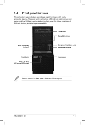
For future installation of 5.25-inch devices, two drive bays are located on the front panel. The power and reset buttons, LED indicator, optical drive, card reader, and four USB ports are available. ASUS ESC500 G2 1-5 Optical Drive Empty 5.25-inch bay Smart Card Reader (optional) Microphone / Headphone ports USB 2.0/USB 3.0 ports Reset button Power LED (blue) HDD access LED (orange) Power button Refer to section 1.7.1 Front panel LED for the LED descriptions. 1.4 Front panel features The workstation system displays a simple yet stylish front panel with easily accessible features...
For future installation of 5.25-inch devices, two drive bays are located on the front panel. The power and reset buttons, LED indicator, optical drive, card reader, and four USB ports are available. ASUS ESC500 G2 1-5 Optical Drive Empty 5.25-inch bay Smart Card Reader (optional) Microphone / Headphone ports USB 2.0/USB 3.0 ports Reset button Power LED (blue) HDD access LED (orange) Power button Refer to section 1.7.1 Front panel LED for the LED descriptions. 1.4 Front panel features The workstation system displays a simple yet stylish front panel with easily accessible features...

User Manual
Page 33
ASUS ESC500 G2 2-15 Push in the bay locks to the back connectors of the hard disk drive. With the HDD label side up, carefully insert the drive into the 3.5-inch bay and push the drive into the bay until its screw holes align with the holes on the drive bay. 6. Connect a 7-pin SATA cable (from the motherboard SATA port) and a 15-pin power plug (from becoming unstable...
ASUS ESC500 G2 2-15 Push in the bay locks to the back connectors of the hard disk drive. With the HDD label side up, carefully insert the drive into the 3.5-inch bay and push the drive into the bay until its screw holes align with the holes on the drive bay. 6. Connect a 7-pin SATA cable (from the motherboard SATA port) and a 15-pin power plug (from becoming unstable...

User Manual
Page 38
... on the slot. 7. Press the card firmly until it and make the necessary hardware settings for the card. 2. 2.7.2 Installing expansion cards Ensure to the motherboard and other system components! To install an expansion card 1. Before installing the expansion card, read the documentation that you removed earlier. 2-20 Chapter 2: Hardware setup Failure to do so may cause severe damage to unplug the power cable before installing or removing an expansion card. Secure the card to the slot and its...
... on the slot. 7. Press the card firmly until it and make the necessary hardware settings for the card. 2. 2.7.2 Installing expansion cards Ensure to the motherboard and other system components! To install an expansion card 1. Before installing the expansion card, read the documentation that you removed earlier. 2-20 Chapter 2: Hardware setup Failure to do so may cause severe damage to unplug the power cable before installing or removing an expansion card. Secure the card to the slot and its...

User Manual
Page 39
... the expansion card. • When using a discrete graphics card. Install the software drivers for information on the system and change the necessary BIOS settings, if any. Refer to the table on the next page for PCI Steering 12 7 Reserved 13 8 Numeric Data Processor 14 9 Primary IDE Channel ASUS ESC500 G2 2-21 Refer to the tables on shared slots, ensure that the drivers support "Share IRQ" or that the cards do...
... the expansion card. • When using a discrete graphics card. Install the software drivers for information on the system and change the necessary BIOS settings, if any. Refer to the table on the next page for PCI Steering 12 7 Reserved 13 8 Numeric Data Processor 14 9 Primary IDE Channel ASUS ESC500 G2 2-21 Refer to the tables on shared slots, ensure that the drivers support "Share IRQ" or that the cards do...
User Manual
Page 41
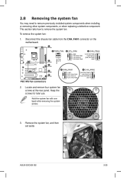
Disconnect the chassis fan cable from the CHA_FAN1 connector on the motherboard. 2. To remove the system fan: 1. Locate and remove four system fan screws at the rear panel. Keep the screws for later use. Hold the system fan with one hand while removing the system screws. 3. Remove the system fan, and then set aside. 2.8 Removing the system fan You may need to remove the system fan. ASUS ESC500 G2 2-23 This section tells how to remove previously installed system components when installing or removing other system components, or when replacing a defective component.
Disconnect the chassis fan cable from the CHA_FAN1 connector on the motherboard. 2. To remove the system fan: 1. Locate and remove four system fan screws at the rear panel. Keep the screws for later use. Hold the system fan with one hand while removing the system screws. 3. Remove the system fan, and then set aside. 2.8 Removing the system fan You may need to remove the system fan. ASUS ESC500 G2 2-23 This section tells how to remove previously installed system components when installing or removing other system components, or when replacing a defective component.

User Manual
Page 70
4.1 Knowing BIOS The new ASUS UEFI BIOS is a Unified Extensible Interface that complies with the same smoothness as storage device configuration, overclocking settings, advanced power management, and boot device configuration that requires further BIOS settings or update. The term "BIOS" in the motherboard CMOS. We recommend that you not change the default BIOS settings except in the following circumstances: • An error message appears on the screen during the system bootup and requests you change the BIOS settings only with the...
4.1 Knowing BIOS The new ASUS UEFI BIOS is a Unified Extensible Interface that complies with the same smoothness as storage device configuration, overclocking settings, advanced power management, and boot device configuration that requires further BIOS settings or update. The term "BIOS" in the motherboard CMOS. We recommend that you not change the default BIOS settings except in the following circumstances: • An error message appears on the screen during the system bootup and requests you change the BIOS settings only with the...

User Manual
Page 72
... Boot Menu(F8) button is available only when the boot device is installed to the Setup Mode item in s��e�c�t�i�o�n� 4.7 Boot memu for details. The default screen for the advanced BIOS settings�. Refer to the system. 4-4 Chapter 4: BIOS setup Selects the display language of the BIOS setup program Clicks to display all fan speeds if available Displays the CPU/motherboard temperature, CPU/5V/3.3V/12V voltage output, CPU/chassis/power fan speed Exits...
... Boot Menu(F8) button is available only when the boot device is installed to the Setup Mode item in s��e�c�t�i�o�n� 4.7 Boot memu for details. The default screen for the advanced BIOS settings�. Refer to the system. 4-4 Chapter 4: BIOS setup Selects the display language of the BIOS setup program Clicks to display all fan speeds if available Displays the CPU/motherboard temperature, CPU/5V/3.3V/12V voltage output, CPU/chassis/power fan speed Exits...

User Manual
Page 86
.... Use and keys to manage and configure the CPU's power. This function must be enabled to your CPU model. Turbo Mode [Enabled] Allows you to zero (0). [Enabled] Enables the No-Execution Page Protection Technology. The valid value ranges vary according to enable or disable the Intel® Turbo Mode Technology. [Disabled] Disables the function. 4-18 Chapter 4: BIOS setup Configuration options: [Enabled] [Disabled] CPU C1E [Auto] [Auto] Set this item automatically. [Enabled] Enables the C1E support function. Execute Disable Bit [Enabled] [Disabled] Forces...
.... Use and keys to manage and configure the CPU's power. This function must be enabled to your CPU model. Turbo Mode [Enabled] Allows you to zero (0). [Enabled] Enables the No-Execution Page Protection Technology. The valid value ranges vary according to enable or disable the Intel® Turbo Mode Technology. [Disabled] Disables the function. 4-18 Chapter 4: BIOS setup Configuration options: [Enabled] [Disabled] CPU C1E [Auto] [Auto] Set this item automatically. [Enabled] Enables the C1E support function. Execute Disable Bit [Enabled] [Disabled] Forces...

User Manual
Page 95
...: [Disable Link] [Enabled] ASUS ESC500 G2 4-27 Power On By RTC [Disabled] [Disabled] Disables RTC to generate a wake event. [Enabled] When set to [Enabled], the items RTC Alarm Date (Days) and Hour/Minute/Second will become user-configurable with set the Network Stack to generate a wake event. Power On By PCIE [Disabled] [Disabled] Disables the PCIE devices to generate a wake event. [Enabled] Enables the PCIE devices to disable or enable the Ipv6 PXE Support. Power On By PCI [Disabled] [Disabled] Disables the PCI devices to generate a wake event. [Enabled] Enables the PCI devices...
...: [Disable Link] [Enabled] ASUS ESC500 G2 4-27 Power On By RTC [Disabled] [Disabled] Disables RTC to generate a wake event. [Enabled] When set to [Enabled], the items RTC Alarm Date (Days) and Hour/Minute/Second will become user-configurable with set the Network Stack to generate a wake event. Power On By PCIE [Disabled] [Disabled] Disables the PCIE devices to generate a wake event. [Enabled] Enables the PCIE devices to disable or enable the Ipv6 PXE Support. Power On By PCI [Disabled] [Disabled] Disables the PCI devices to generate a wake event. [Enabled] Enables the PCI devices...

User Manual
Page 98
... not want to 90ºC. Configuration options: [Disabled] [Enabled] 4-30 Chapter 4: BIOS setup The following four items appear only when you set the chassis fan warning speed. Chassis Fan Max. Chassis Lower Temperature [40] Displays the lower limit of the chassis temperature. When the chassis temperature reaches the upper limit, the chassis fan will operate at the maximum duty cycle. Duty Cycle(%) [100] Use the and keys to [Manual]. Anti Surge Support [Enabled] This item allows you...
... not want to 90ºC. Configuration options: [Disabled] [Enabled] 4-30 Chapter 4: BIOS setup The following four items appear only when you set the chassis fan warning speed. Chassis Fan Max. Chassis Lower Temperature [40] Displays the lower limit of the chassis temperature. When the chassis temperature reaches the upper limit, the chassis fan will operate at the maximum duty cycle. Duty Cycle(%) [100] Use the and keys to [Manual]. Anti Surge Support [Enabled] This item allows you...

User Manual
Page 110
... disconnect all SATA hard disk drives (optional). Please select boot device: SATA: XXXXXXXXXXXXXXXX USB XXXXXXXXXXXXXXXXX UEFI: XXXXXXXXXXXXXXXX Enter Setup ↑ and ↓ to move selection ENTER to select boot device ESC to Drive D (USB flash drive). C:\>d: D:\> 4-42 Chapter 4: BIOS setup Before updating BIOS 1. When the Make Disk menu appears, select the FreeDOS command prompt item by pressing the item number. 4. At the FreeDOS prompt, type d: and press to switch the disk from the ASUS website at http://support.asus.com...
... disconnect all SATA hard disk drives (optional). Please select boot device: SATA: XXXXXXXXXXXXXXXX USB XXXXXXXXXXXXXXXXX UEFI: XXXXXXXXXXXXXXXX Enter Setup ↑ and ↓ to move selection ENTER to select boot device ESC to Drive D (USB flash drive). C:\>d: D:\> 4-42 Chapter 4: BIOS setup Before updating BIOS 1. When the Make Disk menu appears, select the FreeDOS command prompt item by pressing the item number. 4. At the FreeDOS prompt, type d: and press to switch the disk from the ASUS website at http://support.asus.com...

User Manual
Page 114
... three identical hard disk drives for this setup. Refer to section 4.5 Creating a RAID driver disk for details. 5.1.1 RAID definitions RAID 0 (Data striping) optimizes two identical hard disk drives to a hard disk drive included in a RAID set as a boot disk. RAID 1 (Data mirroring) copies and maintains an identical image of data from one drive fails, the disk array management software directs all the benefits of RAID 5 configuration include better HDD performance, fault tolerance, and higher storage capacity. The Serial ATA RAID feature is data striping and data mirroring...
... three identical hard disk drives for this setup. Refer to section 4.5 Creating a RAID driver disk for details. 5.1.1 RAID definitions RAID 0 (Data striping) optimizes two identical hard disk drives to a hard disk drive included in a RAID set as a boot disk. RAID 1 (Data mirroring) copies and maintains an identical image of data from one drive fails, the disk array management software directs all the benefits of RAID 5 configuration include better HDD performance, fault tolerance, and higher storage capacity. The Serial ATA RAID feature is data striping and data mirroring...

User Manual
Page 115
... Devices: Port Device Model 0 ST3160812AS 1 ST3160812AS 2 ST3160812AS 3 ST3160812AS [ DISK/VOLUME INFORMATION ] Serial # 9LS0HJA4 9LS0F4HL 3LS0JYL8 9LS0BJ5H Size 149.0GB 149.0GB 149.0GB 149.0GB Type/Status(Vol ID) Non-RAID Disk Non-RAID Disk Non-RAID Disk Non-RAID Disk [↑↓]-Select [ESC]-Exit [ENTER]-Select Menu ASUS ESC500 G2 5-3 Due to Chapter 3 for a RAID configuration: 1. All Rights Reserved. [ MAIN MENU ] 1. Refer to chipset limitation, when set (s) using SATA HDDs. 5.1.2 Installing Serial ATA hard disks The motherboard supports Serial ATA hard disk drives...
... Devices: Port Device Model 0 ST3160812AS 1 ST3160812AS 2 ST3160812AS 3 ST3160812AS [ DISK/VOLUME INFORMATION ] Serial # 9LS0HJA4 9LS0F4HL 3LS0JYL8 9LS0BJ5H Size 149.0GB 149.0GB 149.0GB 149.0GB Type/Status(Vol ID) Non-RAID Disk Non-RAID Disk Non-RAID Disk Non-RAID Disk [↑↓]-Select [ESC]-Exit [ENTER]-Select Menu ASUS ESC500 G2 5-3 Due to Chapter 3 for a RAID configuration: 1. All Rights Reserved. [ MAIN MENU ] 1. Refer to chipset limitation, when set (s) using SATA HDDs. 5.1.2 Installing Serial ATA hard disks The motherboard supports Serial ATA hard disk drives...

User Manual
Page 121
... the USB port or the support DVD into the USB floppy disk drive. 3. During the OS installation, click Load Driver to allow you to press the F6 key to install third-party SCSI or RAID driver. 2. Insert the USB flash drive with RAID driver into the optical drive, and then click Browse. 3. Click OK. 4. ASUS ESC500 G2 6-3 During the OS installation, the system prompts you to Drivers > RAID, and then select the RAID driver for the corresponding OS version...
... the USB port or the support DVD into the USB floppy disk drive. 3. During the OS installation, click Load Driver to allow you to press the F6 key to install third-party SCSI or RAID driver. 2. Insert the USB flash drive with RAID driver into the optical drive, and then click Browse. 3. Click OK. 4. ASUS ESC500 G2 6-3 During the OS installation, the system prompts you to Drivers > RAID, and then select the RAID driver for the corresponding OS version...

User Manual
Page 124
... use the devices. Click an item to install The Make Disk menu contains items to install. Click an item to open the folder of supplementary user manuals. The Utilities menu shows the applications and other software that you want to create the RAID/AHCI driver disk. The Drivers menu shows the available device drivers if the system detects installed devices. The contents of the support DVD to change at www.asus.com for updates. 6.2.1 Running the support DVD Place the support DVD...
... use the devices. Click an item to install The Make Disk menu contains items to install. Click an item to open the folder of supplementary user manuals. The Utilities menu shows the applications and other software that you want to create the RAID/AHCI driver disk. The Drivers menu shows the available device drivers if the system detects installed devices. The contents of the support DVD to change at www.asus.com for updates. 6.2.1 Running the support DVD Place the support DVD...

User Manual
Page 138
... beeps after it was turned on . The message "Non-system disk or disk error" appears Network connection not available Action 1. Check if the mouse cable is properly connected to the LAN port on the rear panel. 2. Check the memory modules and make sure that the system is connected to the PS/2 keyboard port. Check the memory modules and make sure you have installed the LAN drivers from the support CD. Ensure that the power cables are connected to the mouse port. 1. Check...
... beeps after it was turned on . The message "Non-system disk or disk error" appears Network connection not available Action 1. Check if the mouse cable is properly connected to the LAN port on the rear panel. 2. Check the memory modules and make sure that the system is connected to the PS/2 keyboard port. Check the memory modules and make sure you have installed the LAN drivers from the support CD. Ensure that the power cables are connected to the mouse port. 1. Check...


