
User Guide
Page 4
... 3-26 3.7 ASUS Wireless LAN adapter 3-35 3.7.1 Installing the WLAN Card utilities and driver ...... 3-36 3.7.2 Setting the Windows® XP wireless options ....... 3-36 3.7.3 Other support CD options 3-36 3.7.4 Setup Wizard 3-37 3.7.5 The Control Center utility 3-50 3.7.6 Configuring the wireless LAN adapter by Wireless Settings utility 3-60 Chapter 4: Motherboard Information 4.1 Introduction 4-2 4.2 Motherboard components 4-2 4.3 Motherboard layout 4-5 iv...
... 3-26 3.7 ASUS Wireless LAN adapter 3-35 3.7.1 Installing the WLAN Card utilities and driver ...... 3-36 3.7.2 Setting the Windows® XP wireless options ....... 3-36 3.7.3 Other support CD options 3-36 3.7.4 Setup Wizard 3-37 3.7.5 The Control Center utility 3-50 3.7.6 Configuring the wireless LAN adapter by Wireless Settings utility 3-60 Chapter 4: Motherboard Information 4.1 Introduction 4-2 4.2 Motherboard components 4-2 4.3 Motherboard layout 4-5 iv...
User Guide
Page 8
... and internal components. 2. Chapter 5: BIOS information This chapter tells how to install components in the ASUS DiGiMatrix system. 3. This chapter includes the motherboard layout, jumper settings, and connector locations. 5. viii User Guide The chapter lists the system features ...to change system settings through the BIOS Setup menus and describes the BIOS parameters. 6. Chapter 4: Motherboard Information This chapter gives information about the ASUS DiGiMatrix. This guide is organized This guide contains the following chapters: 1. Chapter 1: System Introduction This ...
... and internal components. 2. Chapter 5: BIOS information This chapter tells how to install components in the ASUS DiGiMatrix system. 3. This chapter includes the motherboard layout, jumper settings, and connector locations. 5. viii User Guide The chapter lists the system features ...to change system settings through the BIOS Setup menus and describes the BIOS parameters. 6. Chapter 4: Motherboard Information This chapter gives information about the ASUS DiGiMatrix. This guide is organized This guide contains the following chapters: 1. Chapter 1: System Introduction This ...
User Guide
Page 10
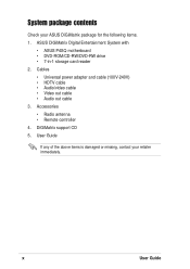
System package contents Check your retailer immediately. x User Guide DiGiMatrix support CD 5. ASUS DiGiMatrix Digital Entertainment System with • ASUS P4SQ motherboard • DVD-ROM/CD-RW/DVD-RW drive • 7-in-1 storage card reader 2. Accessories • Radio antenna • Remote controller 4. Cables • Universal power adapter ...; Audio/video cable • Video out cable • Audio out cable 3. User Guide If any of the above items is damaged or missing, contact your ASUS DiGiMatrix package for the following items. 1.
System package contents Check your retailer immediately. x User Guide DiGiMatrix support CD 5. ASUS DiGiMatrix Digital Entertainment System with • ASUS P4SQ motherboard • DVD-ROM/CD-RW/DVD-RW drive • 7-in-1 storage card reader 2. Accessories • Radio antenna • Remote controller 4. Cables • Universal power adapter ...; Audio/video cable • Video out cable • Audio out cable 3. User Guide If any of the above items is damaged or missing, contact your ASUS DiGiMatrix package for the following items. 1.
User Guide
Page 12
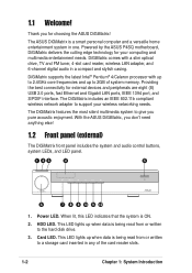
... LED. This LED lights up when data is being read from or written to the hard disk drive. 3. The ASUS DiGiMatrix is ON. 2. Powered by the ASUS P4SQ motherboard, DiGiMatrix delivers the cutting edge technology for external devices and peripherals are eight (8) USB 2.0 ports, fast Ethernet and Gigabit LAN ports, IEEE 1394 port, and S/PDIF...
... LED. This LED lights up when data is being read from or written to the hard disk drive. 3. The ASUS DiGiMatrix is ON. 2. Powered by the ASUS P4SQ motherboard, DiGiMatrix delivers the cutting edge technology for external devices and peripherals are eight (8) USB 2.0 ports, fast Ethernet and Gigabit LAN ports, IEEE 1394 port, and S/PDIF...
User Guide
Page 20
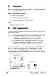
...Off Chapter 2: Basic Installation Use a grounded wrist strap or touch a safely grounded object or to install in the DiGiMatrix system. Hold components by the edges to install 1. The motherboard comes with the component. When lit, this LED indicates that the system is OFF before installing any component, place ...that you have all the components that you plan to a metal object, such as the power supply case, before you install components into the DiGiMatrix system. 1. 2.1 Preparation Before you proceed, make sure that the standby power LED is ON, in sleep mode or in the bag that ...
...Off Chapter 2: Basic Installation Use a grounded wrist strap or touch a safely grounded object or to install in the DiGiMatrix system. Hold components by the edges to install 1. The motherboard comes with the component. When lit, this LED indicates that the system is OFF before installing any component, place ...that you have all the components that you plan to a metal object, such as the power supply case, before you install components into the DiGiMatrix system. 1. 2.1 Preparation Before you proceed, make sure that the standby power LED is ON, in sleep mode or in the bag that ...
User Guide
Page 24
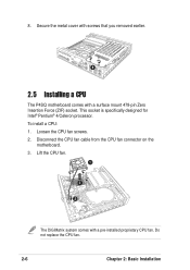
8. This socket is specifically designed for Intel® Pentium® 4/Celeron processor. Disconnect the CPU fan cable from the CPU fan connector on the motherboard. 3. Lift the CPU fan. 1 3 2 The DiGiMatrix system comes with a surface mount 478-pin Zero Insertion Force (ZIF) socket. Loosen the CPU fan screws. 2. Do not replace the CPU fan. 2-6 Chapter 2: Basic Installation Secure the metal cover with screws that you removed earlier. 8 2.5 Installing a CPU The P4SQ motherboard comes with a pre-installed proprietary CPU fan. To install a CPU: 1.
8. This socket is specifically designed for Intel® Pentium® 4/Celeron processor. Disconnect the CPU fan cable from the CPU fan connector on the motherboard. 3. Lift the CPU fan. 1 3 2 The DiGiMatrix system comes with a surface mount 478-pin Zero Insertion Force (ZIF) socket. Loosen the CPU fan screws. 2. Do not replace the CPU fan. 2-6 Chapter 2: Basic Installation Secure the metal cover with screws that you removed earlier. 8 2.5 Installing a CPU The P4SQ motherboard comes with a pre-installed proprietary CPU fan. To install a CPU: 1.
User Guide
Page 25
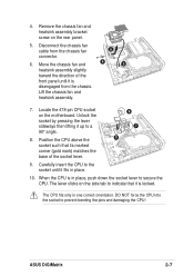
... and damaging the CPU! Disconnect the chassis fan cable from the chassis. Lift the chassis fan and heatsink assembly. 7. ASUS DiGiMatrix 2-7 Remove the chassis fan and heatsink assembly bracket screw on the motherboard. DO NOT force the CPU into the socket to secure the CPU. Position the CPU above the socket such that...
... and damaging the CPU! Disconnect the chassis fan cable from the chassis. Lift the chassis fan and heatsink assembly. 7. ASUS DiGiMatrix 2-7 Remove the chassis fan and heatsink assembly bracket screw on the motherboard. DO NOT force the CPU into the socket to secure the CPU. Position the CPU above the socket such that...

User Guide
Page 26
... chassis fan connector. 14. Align the bracket screw hole with the screw you removed earlier. 11 12 13 13. Doing so may damage the motherboard. 2-8 Chapter 2: Basic Installation Secure the chassis fan and heatsink assembly with the rear panel screw hole. 12. Do not overtighten the CPU fan... screws! Connect the chassis fan cable to the motherboard. 14 15. Reinstall the chassis fan and heatsink assembly. Fasten the CPU fan screws to the chassis fan connector. Connect the CPU fan...
... chassis fan connector. 14. Align the bracket screw hole with the screw you removed earlier. 11 12 13 13. Doing so may damage the motherboard. 2-8 Chapter 2: Basic Installation Secure the chassis fan and heatsink assembly with the rear panel screw hole. 12. Do not overtighten the CPU fan... screws! Connect the chassis fan cable to the motherboard. 14 15. Reinstall the chassis fan and heatsink assembly. Fasten the CPU fan screws to the chassis fan connector. Connect the CPU fan...
User Guide
Page 27
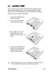
...is keyed with two Double Data Rate (DDR) Dual Inline Memory Module (DIMM) sockets. ASUS DiGiMatrix 2-9 Firmly insert the DIMM into a socket to install a DDR DIMM. 1. Locate the two DIMM sockets on the motherboard. 2. These sockets support up to 2GB system memory using unbuffered non-ECC PC2700/2100/...1600 DIMMs. Follow these steps to avoid damaging the DIMM. 2.6 Installing a DIMM The motherboard comes with a notch so that the notch on...
...is keyed with two Double Data Rate (DDR) Dual Inline Memory Module (DIMM) sockets. ASUS DiGiMatrix 2-9 Firmly insert the DIMM into a socket to install a DDR DIMM. 1. Locate the two DIMM sockets on the motherboard. 2. These sockets support up to 2GB system memory using unbuffered non-ECC PC2700/2100/...1600 DIMMs. Follow these steps to avoid damaging the DIMM. 2.6 Installing a DIMM The motherboard comes with a notch so that the notch on...
User Guide
Page 34
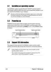
... for more information. 3.2 Powering up 3.1 Installing an operating system The DiGiMatrix system supports Windows® 2000/XP operating systems (OS). Visit the ASUS website for general reference only. Because motherboard settings and hardware options vary, use the setup procedures presented in this ...chapter for updates. 3-2 Chapter 3: Starting up DiGiMatrix has two power buttons located in the ...
... for more information. 3.2 Powering up 3.1 Installing an operating system The DiGiMatrix system supports Windows® 2000/XP operating systems (OS). Visit the ASUS website for general reference only. Because motherboard settings and hardware options vary, use the setup procedures presented in this ...chapter for updates. 3-2 Chapter 3: Starting up DiGiMatrix has two power buttons located in the ...
User Guide
Page 37
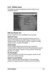
... 2002 anti-virus program. The Acrobat Reader® software is for details. ASUS Update This item installs the ASUS Update that the motherboard supports. See page 3-9 for viewing files saved in Portable Document Format (PDF). See page 3-7 for detailed information. ASUS DiGiMatrix 3-5 ASUS PC Probe This utility continuously monitors vital system information such as fan rotations...
... 2002 anti-virus program. The Acrobat Reader® software is for details. ASUS Update This item installs the ASUS Update that the motherboard supports. See page 3-9 for viewing files saved in Portable Document Format (PDF). See page 3-7 for detailed information. ASUS DiGiMatrix 3-5 ASUS PC Probe This utility continuously monitors vital system information such as fan rotations...
User Guide
Page 38
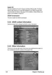
...16 for details on Music Wizard and page 3-19 for details on the motherboard and the contents of the support CD. 3-6 Chapter 3: Starting up ASUS Screensaver This item installs the ASUS screensaver. 3.3.4 ASUS contact information Click the Contact tab to your HDD and play them using the... Audio DJ feature. The Music Wizard utility allows you to save MP3 playlists to display the ASUS contact information. 3.3.5 Other ...
...16 for details on Music Wizard and page 3-19 for details on the motherboard and the contents of the support CD. 3-6 Chapter 3: Starting up ASUS Screensaver This item installs the ASUS screensaver. 3.3.4 ASUS contact information Click the Contact tab to your HDD and play them using the... Audio DJ feature. The Music Wizard utility allows you to save MP3 playlists to display the ASUS contact information. 3.3.5 Other ...
User Guide
Page 39
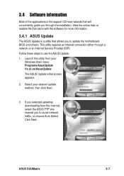
... Windows Start menu: Programs/AsusUpdate Vx.xx.xx/AsusUpdate The ASUS Update initial screen appears. 2. ASUS DiGiMatrix 3-7 Follow these steps to use the ASUS Update. 1. If you selected updating/ downloading from your desired... update method, then click Next. 3. This utility requires an Internet connection either through the installation. 3.4 Software information Most of the applications in the support CD have wizards that allows you to update the motherboard...
... Windows Start menu: Programs/AsusUpdate Vx.xx.xx/AsusUpdate The ASUS Update initial screen appears. 2. ASUS DiGiMatrix 3-7 Follow these steps to use the ASUS Update. 1. If you selected updating/ downloading from your desired... update method, then click Next. 3. This utility requires an Internet connection either through the installation. 3.4 Software information Most of the applications in the support CD have wizards that allows you to update the motherboard...
User Guide
Page 45
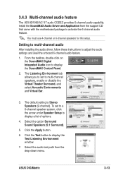
... test path from the support CD that came with the motherboard package to display the SoundMAX Control Panel. 2. The default setting is Stereo Speakers (2-channel). Click the Test button to adjust the audio settings and avail the onboard 6-channel audio feature. 1. ASUS DiGiMatrix 3-13 You must use 4-channel or 6-channel speakers for this...
... test path from the support CD that came with the motherboard package to display the SoundMAX Control Panel. 2. The default setting is Stereo Speakers (2-channel). Click the Test button to adjust the audio settings and avail the onboard 6-channel audio feature. 1. ASUS DiGiMatrix 3-13 You must use 4-channel or 6-channel speakers for this...
User Guide
Page 105
This chapter includes the motherboard layout, jumper settings, and connector locations. ASUS DiGiMatrix Motherboard Info Chapter 4 This chapter gives information about the P4SQ motherboard that came with the system.
This chapter includes the motherboard layout, jumper settings, and connector locations. ASUS DiGiMatrix Motherboard Info Chapter 4 This chapter gives information about the P4SQ motherboard that came with the system.
User Guide
Page 106
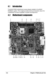
4.1 Introduction The ASUS P4SQ motherboard comes already installed in the ASUS DiGiMatrix system. This chapter provides technical information about the motherboard for future upgrades or system reconfiguration. 4.2 Motherboard components 1 2 3 4 56 7 20 1918 171615 14 13 12 11 10 9 8 4-2 Chapter 4: Motherboard Info
4.1 Introduction The ASUS P4SQ motherboard comes already installed in the ASUS DiGiMatrix system. This chapter provides technical information about the motherboard for future upgrades or system reconfiguration. 4.2 Motherboard components 1 2 3 4 56 7 20 1918 171615 14 13 12 11 10 9 8 4-2 Chapter 4: Motherboard Info
User Guide
Page 108
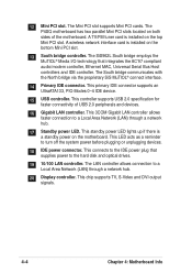
...Universal Serial Bus Host controllers and IDE controller. A wireless network interface card is installed on the motherboard. This chip supports TV, S-Video and DVI output signals. 4-4 Chapter 4: Motherboard Info 12 Mini PCI slot. This connects to turn off the system power before plugging or unplugging... 18 IDE power connector. This primary IDE connector supports an UltraATA133, PIO Modes 0~4 IDE device. 15 USB controller. The P4SQ motherboard has two parallel Mini PCI slots located on the bottom Mini PCI slot. 13 South bridge controller. This controller supports USB 2.0 ...
...Universal Serial Bus Host controllers and IDE controller. A wireless network interface card is installed on the motherboard. This chip supports TV, S-Video and DVI output signals. 4-4 Chapter 4: Motherboard Info 12 Mini PCI slot. This connects to turn off the system power before plugging or unplugging... 18 IDE power connector. This primary IDE connector supports an UltraATA133, PIO Modes 0~4 IDE device. 15 USB controller. The P4SQ motherboard has two parallel Mini PCI slots located on the bottom Mini PCI slot. 13 South bridge controller. This controller supports USB 2.0 ...
User Guide
Page 110
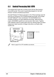
Gold Arrow P4SQ P4SQ Socket 478 Refer to page 2-6 for the Intel® Pentium® 4/Celeron Northwood processor. 4.4 Central Processing Unit (CPU) The motherboard comes with a surface mount 478-pin Zero Insertion Force (ZIF) socket. The Intel® Pentium® 4/Celeron processor in the 478-pin package uses the ... the hyper-pipelined technology, rapid execution engine, 533/400MHz system bus, and execution trace cache. This socket is specifically designed for CPU installation procedures. 4-6 Chapter 4: Motherboard Info
Gold Arrow P4SQ P4SQ Socket 478 Refer to page 2-6 for the Intel® Pentium® 4/Celeron Northwood processor. 4.4 Central Processing Unit (CPU) The motherboard comes with a surface mount 478-pin Zero Insertion Force (ZIF) socket. The Intel® Pentium® 4/Celeron processor in the 478-pin package uses the ... the hyper-pipelined technology, rapid execution engine, 533/400MHz system bus, and execution trace cache. This socket is specifically designed for CPU installation procedures. 4-6 Chapter 4: Motherboard Info
User Guide
Page 111
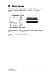
ASUS DiGiMatrix 4-7 4.5 System memory The motherboard has two Double Data Rate (DDR) DIMM sockets that supports up to page 2-9 for DIMM installation procedures. Refer to 2GB unbuffered non-ECC PC2700/2100/1600 DDR DIMMs. 104 Pins 80 Pins P4SQ P4SQ 184-Pin DDR DIMM Sockets You may install any DDR DIMMs with 64MB, 128MB, 256MB, 512MB, and 1GB densities into the two DIMM sockets.
ASUS DiGiMatrix 4-7 4.5 System memory The motherboard has two Double Data Rate (DDR) DIMM sockets that supports up to page 2-9 for DIMM installation procedures. Refer to 2GB unbuffered non-ECC PC2700/2100/1600 DDR DIMMs. 104 Pins 80 Pins P4SQ P4SQ 184-Pin DDR DIMM Sockets You may install any DDR DIMMs with 64MB, 128MB, 256MB, 512MB, and 1GB densities into the two DIMM sockets.
User Guide
Page 112
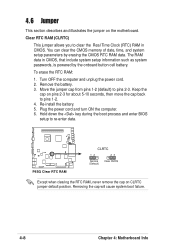
Re-install the battery. 5. Removing the cap will cause system boot failure. 4-8 Chapter 4: Motherboard Info The RAM data in CMOS. Hold down the key during the boot process and enter BIOS setup to pins 2-3. P4SQ P4SQ Clear RTC RAM ...CLRTC 12 23 Normal (Default) Clear CMOS Except when clearing the RTC RAM, never remove the cap on the motherboard. Plug the power cord and turn ON the computer. 6. You can clear the CMOS memory of date, time, and system setup parameters by the onboard...
Re-install the battery. 5. Removing the cap will cause system boot failure. 4-8 Chapter 4: Motherboard Info The RAM data in CMOS. Hold down the key during the boot process and enter BIOS setup to pins 2-3. P4SQ P4SQ Clear RTC RAM ...CLRTC 12 23 Normal (Default) Clear CMOS Except when clearing the RTC RAM, never remove the cap on the motherboard. Plug the power cord and turn ON the computer. 6. You can clear the CMOS memory of date, time, and system setup parameters by the onboard...


