
CUSL2-C BP User Manual
Page 6
... measures: • Re-orient or relocate the receiving antenna. • Increase the separation between the equipment and receiver. • Connect the equipment to an outlet on a circuit different from that to which can radiate radio frequency energy and, if not installed and ...Government Printing Office. Cet appareil numérique de la classe B est conforme à la norme NMB-003 du Canada. 6 ASUS CUSL2-C Black PearlUser's Manual Operation is no guarantee that may cause harmful interference to provide reasonable protection against harmful interference in the Radio Interference ...
... measures: • Re-orient or relocate the receiving antenna. • Increase the separation between the equipment and receiver. • Connect the equipment to an outlet on a circuit different from that to which can radiate radio frequency energy and, if not installed and ...Government Printing Office. Cet appareil numérique de la classe B est conforme à la norme NMB-003 du Canada. 6 ASUS CUSL2-C Black PearlUser's Manual Operation is no guarantee that may cause harmful interference to provide reasonable protection against harmful interference in the Radio Interference ...

CUSL2-C BP User Manual
Page 11
...hard disk drive. Provides Vcore and CPU/ SDRAM frequency adjustments, boot block write protection, and HD/SCSI/MO/ ZIP/CD/Floppy boot selection. ASUS CUSL2-C Black PearlUser's Manual 11 2. This acts as a reminder to the user to turn OFF the power before plugging and unplugging devices so as... (PCI supports up screens with this easy-to-use interface which is standby power to -use DOS utility. • SmartCard Reader: Onboard header connects directly to support very affordable multichannel audio, V.90 analog modem, Home PNA, 10/100 Ethernet networking, and USB hub. • PCI Expansion ...
...hard disk drive. Provides Vcore and CPU/ SDRAM frequency adjustments, boot block write protection, and HD/SCSI/MO/ ZIP/CD/Floppy boot selection. ASUS CUSL2-C Black PearlUser's Manual 11 2. This acts as a reminder to the user to turn OFF the power before plugging and unplugging devices so as... (PCI supports up screens with this easy-to-use interface which is standby power to -use DOS utility. • SmartCard Reader: Onboard header connects directly to support very affordable multichannel audio, V.90 analog modem, Home PNA, 10/100 Ethernet networking, and USB hub. • PCI Expansion ...

CUSL2-C BP User Manual
Page 19
...the motherboard. H/W SETUP Motherboard Settings ® CUSL2-C BP CUSL2-C BP Onboard LED PLED2 ON Standby Power OFF Powered Off ASUS CUSL2-C Black PearlUser's Manual 19 Computer motherboards and ...expansion cards contain very delicate Integrated Circuit (IC) chips. 3. Use a grounded wrist strap before you must complete the following steps: • Check Motherboard Settings • Install Memory Modules • Install the Central Processing Unit (CPU) • Install Expansion Cards • Connect...
...the motherboard. H/W SETUP Motherboard Settings ® CUSL2-C BP CUSL2-C BP Onboard LED PLED2 ON Standby Power OFF Powered Off ASUS CUSL2-C Black PearlUser's Manual 19 Computer motherboards and ...expansion cards contain very delicate Integrated Circuit (IC) chips. 3. Use a grounded wrist strap before you must complete the following steps: • Check Motherboard Settings • Install Memory Modules • Install the Central Processing Unit (CPU) • Install Expansion Cards • Connect...

CUSL2-C BP User Manual
Page 28
...lever while holding down the CPU. NOTE: Do not forget to prevent overheating. H/W SETUP CPU Pentium III ® CUSL2-C BP CUSL2-C BP Socket 370 Gold Arrow 28 ASUS CUSL2-C Black PearlUser's Manual CAUTION! Be careful not to it by regularly checking that covers the face of the four corners...Because the CPU has a corner pin for reference only; Locate the CPU fan connector (see 3.1 Motherboard Layout or 3.8 Connectors) and connect the CPU fan cable to scrape the motherboard when mounting a clampstyle processor fan or else damage may install an auxiliary fan, if necessary....
...lever while holding down the CPU. NOTE: Do not forget to prevent overheating. H/W SETUP CPU Pentium III ® CUSL2-C BP CUSL2-C BP Socket 370 Gold Arrow 28 ASUS CUSL2-C Black PearlUser's Manual CAUTION! Be careful not to it by regularly checking that covers the face of the four corners...Because the CPU has a corner pin for reference only; Locate the CPU fan connector (see 3.1 Motherboard Layout or 3.8 Connectors) and connect the CPU fan cable to scrape the motherboard when mounting a clampstyle processor fan or else damage may install an auxiliary fan, if necessary....

CUSL2-C BP User Manual
Page 32
...mini DIN adapter on standard AT keyboards. H/W SETUP Connectors 2) PS/2 Keyboard Connector (Purple 6-pin PS2KBMS) This connection is for connectors or power sources. This connector will direct IRQ12 to the power connector on hard drives and CD...-ROM drives, but may be connected with the second drive connector no more than 15 cm (6 in.) from jumpers in the Motherboard Layout. 3. ...use IRQ12. IDE ribbon cable must be exceptions. PS/2 Keyboard (6-pin Female) 32 ASUS CUSL2-C Black PearlUser's Manual
...mini DIN adapter on standard AT keyboards. H/W SETUP Connectors 2) PS/2 Keyboard Connector (Purple 6-pin PS2KBMS) This connection is for connectors or power sources. This connector will direct IRQ12 to the power connector on hard drives and CD...-ROM drives, but may be connected with the second drive connector no more than 15 cm (6 in.) from jumpers in the Motherboard Layout. 3. ...use IRQ12. IDE ribbon cable must be exceptions. PS/2 Keyboard (6-pin Female) 32 ASUS CUSL2-C Black PearlUser's Manual

CUSL2-C BP User Manual
Page 33
... for settings. COM1 COM2 Serial Ports (9-pin Male) ASUS CUSL2-C Black PearlUser's Manual 33 H/W SETUP Connectors 5) Serial Port Connectors (Teal/Turquoise 9-pin COM1, 10-1 pin COM2) Two serial ports are available for a mouse or other serial devices. NOTE: Serial printers must be connected to the chassis. See Onboard Serial Port 1/2 in ... (see USB Headers later in 4.4.2 I /O Device Configuration). HARDWARE SETUP 3) Universal Serial BUS Ports 0 & 1 (Black two 4-pin USB) Two USB ports are ready for connecting USB devices. 3. Parallel (Printer) Port (25-pin Female) 3.
... for settings. COM1 COM2 Serial Ports (9-pin Male) ASUS CUSL2-C Black PearlUser's Manual 33 H/W SETUP Connectors 5) Serial Port Connectors (Teal/Turquoise 9-pin COM1, 10-1 pin COM2) Two serial ports are available for a mouse or other serial devices. NOTE: Serial printers must be connected to the chassis. See Onboard Serial Port 1/2 in ... (see USB Headers later in 4.4.2 I /O Device Configuration). HARDWARE SETUP 3) Universal Serial BUS Ports 0 & 1 (Black two 4-pin USB) Two USB ports are ready for connecting USB devices. 3. Parallel (Printer) Port (25-pin Female) 3.

CUSL2-C BP User Manual
Page 34
... provided floppy drive ribbon cable. FLOPPY ® CUSL2-C BP CUSL2-C BP Floppy Disk Drive Connector NOTE: Orient the red markings on the other audio sources to be connected to headphones or preferably powered speakers. 3. HARDWARE ...connect game joysticks or game pads to prevent inserting in the wrong orientation when using ribbon cables with pin 5 plugged). H/W SETUP Connectors 7) Audio Port Connectors (Three 1/8" GAME_AUDIO) (optional) Line Out (lime) can be recorded by your computer or played through the Line Out (lime). Game/MIDI (15-pin Female) 3. PIN 1 34 ASUS CUSL2...
... provided floppy drive ribbon cable. FLOPPY ® CUSL2-C BP CUSL2-C BP Floppy Disk Drive Connector NOTE: Orient the red markings on the other audio sources to be connected to headphones or preferably powered speakers. 3. HARDWARE ...connect game joysticks or game pads to prevent inserting in the wrong orientation when using ribbon cables with pin 5 plugged). H/W SETUP Connectors 7) Audio Port Connectors (Three 1/8" GAME_AUDIO) (optional) Line Out (lime) can be recorded by your computer or played through the Line Out (lime). Game/MIDI (15-pin Female) 3. PIN 1 34 ASUS CUSL2...
CUSL2-C BP User Manual
Page 35
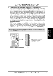
...cable to the secondary IDE connector. one operating system on an IDE drive and another for 100MByte/sec transfer rates. ® CUSL2-C BP CUSL2-C BP IDE Connectors NOTE: Orient the red markings (usually zigzag) on a SCSI drive and select the boot disk through 4.4.1 Advanced ...devices be both Masters with pin 20 plugged). H/W SETUP DCMoAnnCehcatnornsels ASUS CUSL2-C Black PearlUser's Manual 35 Please refer to your hard disk documentation for the jumper settings. You may configure two hard disks to be connected to PIN 1. PIN 1 Secondary IDE Connector Primary IDE Connector ...
...cable to the secondary IDE connector. one operating system on an IDE drive and another for 100MByte/sec transfer rates. ® CUSL2-C BP CUSL2-C BP IDE Connectors NOTE: Orient the red markings (usually zigzag) on a SCSI drive and select the boot disk through 4.4.1 Advanced ...devices be both Masters with pin 20 plugged). H/W SETUP DCMoAnnCehcatnornsels ASUS CUSL2-C Black PearlUser's Manual 35 Please refer to your hard disk documentation for the jumper settings. You may configure two hard disks to be connected to PIN 1. PIN 1 Secondary IDE Connector Primary IDE Connector ...

CUSL2-C BP User Manual
Page 36
... fans so that the heat sink fins allow airflow to light up. 3. Rotation +12V GND ® CUSL2-C BP CUSL2-C BP 12-Volt Cooling Fan Power Rotation +12V GND CPU_FAN GND +12V Rotation PWR_FAN CHA_FAN 36 ASUS CUSL2-C Black PearlUser's Manual Connect the fan's plug to the cabinet's IDE activity LED. Read and write activity by a specially designed...
... fans so that the heat sink fins allow airflow to light up. 3. Rotation +12V GND ® CUSL2-C BP CUSL2-C BP 12-Volt Cooling Fan Power Rotation +12V GND CPU_FAN GND +12V Rotation PWR_FAN CHA_FAN 36 ASUS CUSL2-C Black PearlUser's Manual Connect the fan's plug to the cabinet's IDE activity LED. Read and write activity by a specially designed...

CUSL2-C BP User Manual
Page 37
... disk drive. VCC NC SCRFET# SCRCLK RFU1 GND NC2 LED NC SCRREST RFU2 SCRUI SCRRES# 1 ® CUSL2-C BP CUSL2-C BP SmartCard Connector ASUS CUSL2-C Black PearlUser's Manual 37 If you are not using an ASUS iPanel, you to connect an optional ASUS iPanel, an easy to access drive bay with front I/O ports, status LEDs, and space reserved for both...
... disk drive. VCC NC SCRFET# SCRCLK RFU1 GND NC2 LED NC SCRREST RFU2 SCRUI SCRRES# 1 ® CUSL2-C BP CUSL2-C BP SmartCard Connector ASUS CUSL2-C Black PearlUser's Manual 37 If you are not using an ASUS iPanel, you to connect an optional ASUS iPanel, an easy to access drive bay with front I/O ports, status LEDs, and space reserved for both...

CUSL2-C BP User Manual
Page 38
.... When any removable components. If the chassis intrusion lead is not used, a jumper cap must be available from the chassis to connect to the chassis panel or on any chassis component is removed, the contact should be placed over the pins to...15) Chassis Intrusion Lead (2-pin ACHA) This lead is , multiple chips can be connected to the same bus and each one can then be installed to this lead. H/W SETUP Connectors ® CUSL2-C BP CUSL2-C BP Chassis Open Alarm Lead ACHA 38 ASUS CUSL2-C Black PearlUser's Manual 3. that is for a chassis designed for chassis intrusion detection...
.... When any removable components. If the chassis intrusion lead is not used, a jumper cap must be available from the chassis to connect to the chassis panel or on any chassis component is removed, the contact should be placed over the pins to...15) Chassis Intrusion Lead (2-pin ACHA) This lead is , multiple chips can be connected to the same bus and each one can then be installed to this lead. H/W SETUP Connectors ® CUSL2-C BP CUSL2-C BP Chassis Open Alarm Lead ACHA 38 ASUS CUSL2-C Black PearlUser's Manual 3. that is for a chassis designed for chassis intrusion detection...

CUSL2-C BP User Manual
Page 39
... WOL_CON) This connector connects to internal modem cards with a Wake-On-LAN output, such as the ASUS PCI-L101 Ethernet card (see 4.5.1 Power Up Control) and that Wake On LAN or PCI Modem is detected through the LAN card. H/W SETUP Connectors WOR_CON ® CUSL2-C BP CUSL2-C BP Wake-On-Ring Connector Ring# Ground 2 1 ASUS CUSL2-C Black PearlUser's Manual...
... WOL_CON) This connector connects to internal modem cards with a Wake-On-LAN output, such as the ASUS PCI-L101 Ethernet card (see 4.5.1 Power Up Control) and that Wake On LAN or PCI Modem is detected through the LAN card. H/W SETUP Connectors WOR_CON ® CUSL2-C BP CUSL2-C BP Wake-On-Ring Connector Ring# Ground 2 1 ASUS CUSL2-C Black PearlUser's Manual...

CUSL2-C BP User Manual
Page 40
USBPWR USBP2USBP2+ GND GND USBP5+ USBP5USBPWR ® CUSL2-C BP CUSL2-C BP USB Headers USB2 1 USB56 19) Power Supply Thermal Sensor Connector (2-pin JTPWR) If you have a power supply with thermal monitoring, connect its thermal sensor cable to an open slot on the back panels ...on your chassis. Connect the 5-pin ribbon cables from the provided 2-port USB connector set to the two midboard 5-pin USB headers and mount the USB connector set to this connector. ® CUSL2-C BP CUSL2-C BP Thermal Sensor Connector JTPWR Power Supply Thermal Sensor 40 ASUS CUSL2-C Black PearlUser's Manual...
USBPWR USBP2USBP2+ GND GND USBP5+ USBP5USBPWR ® CUSL2-C BP CUSL2-C BP USB Headers USB2 1 USB56 19) Power Supply Thermal Sensor Connector (2-pin JTPWR) If you have a power supply with thermal monitoring, connect its thermal sensor cable to an open slot on the back panels ...on your chassis. Connect the 5-pin ribbon cables from the provided 2-port USB connector set to the two midboard 5-pin USB headers and mount the USB connector set to this connector. ® CUSL2-C BP CUSL2-C BP Thermal Sensor Connector JTPWR Power Supply Thermal Sensor 40 ASUS CUSL2-C Black PearlUser's Manual...

CUSL2-C BP User Manual
Page 41
...your ATX power supply must supply at least 10mA (750mA recommended) on the +5-volt lead and at least 750mA +5VSB. ® CUSL2-C BP CUSL2-C BP ATX Power Connector +3.3 Volts -12.0 Volts Ground Power Supply On Ground Ground Ground -5.0 Volts +5.0 Volts +5.0 Volts +3.3 Volts +3.3 Volts... Volts Ground Power Good +5V Standby +12.0 Volts 3. For WakeOn-LAN support, your power supply is inadequate. H/W SETUP Connectors ASUS CUSL2-C Black PearlUser's Manual 41 Your system may become unstable/unreliable and may experience difficulty in one orientation because of the different hole sizes....
...your ATX power supply must supply at least 10mA (750mA recommended) on the +5-volt lead and at least 750mA +5VSB. ® CUSL2-C BP CUSL2-C BP ATX Power Connector +3.3 Volts -12.0 Volts Ground Power Supply On Ground Ground Ground -5.0 Volts +5.0 Volts +5.0 Volts +3.3 Volts +3.3 Volts... Volts Ground Power Good +5V Standby +12.0 Volts 3. For WakeOn-LAN support, your power supply is inadequate. H/W SETUP Connectors ASUS CUSL2-C Black PearlUser's Manual 41 Your system may become unstable/unreliable and may experience difficulty in one orientation because of the different hole sizes....

CUSL2-C BP User Manual
Page 42
H/W SETUP Connectors ® CUSL2-C BP CUSL2-C BP System Panel Connectors Message LED SMI Lead Reset SW ATX Power Switch* * Requires an ATX power supply. 21) System Power LED Lead (3-1 pin PWRLED) This 3-1 pin connector connects the system power LED, which lights when the system is powered on...system power LED shows the status of the system's power supply. 42 ASUS CUSL2-C Black PearlUser's Manual Only SPEAKER will turn off . board locking. 23) System Warning Speaker Connector (4-pin SPEAKER) This 4-pin connector connects to prolong the life of the system's power. 27) Reset Switch ...
H/W SETUP Connectors ® CUSL2-C BP CUSL2-C BP System Panel Connectors Message LED SMI Lead Reset SW ATX Power Switch* * Requires an ATX power supply. 21) System Power LED Lead (3-1 pin PWRLED) This 3-1 pin connector connects the system power LED, which lights when the system is powered on...system power LED shows the status of the system's power supply. 42 ASUS CUSL2-C Black PearlUser's Manual Only SPEAKER will turn off . board locking. 23) System Warning Speaker Connector (4-pin SPEAKER) This 4-pin connector connects to prolong the life of the system's power. 27) Reset Switch ...

CUSL2-C BP User Manual
Page 43
...or switch between orange and green after the system's if it has a power standby feature. While the tests are running at a lower frequency ASUS CUSL2-C Black PearlUser's Manual 43 H/W SETUP Powering Up 3. External SCSI devices (starting with "green" standards or if it complies with the last ...switch on the screen. After all switches are made, close the system case cover. 2. Your system power. Recheck your jumper settings and connections or call your country (220V-240V or 110-120V). 3. 3. Award BIOS Beep Codes Beep One short beep when displaying logo Long beeps...
...or switch between orange and green after the system's if it has a power standby feature. While the tests are running at a lower frequency ASUS CUSL2-C Black PearlUser's Manual 43 H/W SETUP Powering Up 3. External SCSI devices (starting with "green" standards or if it complies with the last ...switch on the screen. After all switches are made, close the system case cover. 2. Your system power. Recheck your jumper settings and connections or call your country (220V-240V or 110-120V). 3. 3. Award BIOS Beep Codes Beep One short beep when displaying logo Long beeps...

CUSL2-C BP User Manual
Page 65
If your system already has a second serial port connected to support a Smart Card Reader, select the Smart Card Read mode. If you want to the onboard COM2 connector, it will not be available. Configuration options: [3] [4] [5] [7] [9] [10] [11] [12] [14] [15] Onboard CIR I /O Device Config ASUS CUSL2-C Black PearlUser's Manual 65 Configuration options: [Disabled] [378H...
If your system already has a second serial port connected to support a Smart Card Reader, select the Smart Card Read mode. If you want to the onboard COM2 connector, it will not be available. Configuration options: [3] [4] [5] [7] [9] [10] [11] [12] [14] [15] Onboard CIR I /O Device Config ASUS CUSL2-C Black PearlUser's Manual 65 Configuration options: [Disabled] [378H...

CUSL2-C BP User Manual
Page 71
...: This feature requires an optional network interface card with WakeOn-LAN and an ATX power supply with at least 720mA +5V standby power. ASUS CUSL2-C Black PearlUser's Manual 71 Thus connection cannot be booted from another computer via a network by sending a wake-up the computer when the external modem receives a call while the...
...: This feature requires an optional network interface card with WakeOn-LAN and an ATX power supply with at least 720mA +5V standby power. ASUS CUSL2-C Black PearlUser's Manual 71 Thus connection cannot be booted from another computer via a network by sending a wake-up the computer when the external modem receives a call while the...

CUSL2-C BP User Manual
Page 74
... Device Select [INT18 Device (Network)] Configuration options: [Disabled] [SCSI Boot Device] [INT18 Device (Network)] [LANDesk (R) Service Agent] 74 ASUS CUSL2-C Black PearlUser's Manual Configuration fields include Removable Devices, IDE Hard Drive, ATAPI CD-ROM, and Other Boot Device. BIOS SETUP Boot Menu Boot... By using the or key, you can promote devices and by using the up . Pressing [Enter] will show the product IDs of all connected IDE hard disk drives. Removable Device [Legacy Floppy] Configuration options: [Disabled] [Legacy Floppy] [LS120] [ZIP-100] [ATAPI MO] IDE ...
... Device Select [INT18 Device (Network)] Configuration options: [Disabled] [SCSI Boot Device] [INT18 Device (Network)] [LANDesk (R) Service Agent] 74 ASUS CUSL2-C Black PearlUser's Manual Configuration fields include Removable Devices, IDE Hard Drive, ATAPI CD-ROM, and Other Boot Device. BIOS SETUP Boot Menu Boot... By using the or key, you can promote devices and by using the up . Pressing [Enter] will show the product IDs of all connected IDE hard disk drives. Removable Device [Legacy Floppy] Configuration options: [Disabled] [Legacy Floppy] [LS120] [ZIP-100] [ATAPI MO] IDE ...

CUSL2-C BP User Manual
Page 83
... all Smart Card programs. The Windbond Smart Manager application is configured, the log on " security mode. 6.1.1 Setting Up Smart Manager Connect the Smart Card Reader to the CUSL2-C-BP; (refer to Section 3, Hardware Setup for the connector location.) Boot up the PC and enter BIOS (press ) to change the... up only, or in this order: 1. browse the CD for all new plug-andplay devices except for you install a Smart Card reader. ASUS CUSL2-C Black PearlUser's Manual 83 Then browse the Support CD ROM and locate the Smart Card folder; three sub-folders, Components, Driver and App ...
... all Smart Card programs. The Windbond Smart Manager application is configured, the log on " security mode. 6.1.1 Setting Up Smart Manager Connect the Smart Card Reader to the CUSL2-C-BP; (refer to Section 3, Hardware Setup for the connector location.) Boot up the PC and enter BIOS (press ) to change the... up only, or in this order: 1. browse the CD for all new plug-andplay devices except for you install a Smart Card reader. ASUS CUSL2-C Black PearlUser's Manual 83 Then browse the Support CD ROM and locate the Smart Card folder; three sub-folders, Components, Driver and App ...


