CUSI-M User Manual
Page 1
R CUSI-M Socket 370 microATX Motherboard USER'S MANUAL
R CUSI-M Socket 370 microATX Motherboard USER'S MANUAL
CUSI-M User Manual
Page 4
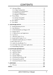
HARDWARE SETUP 14 3.1 CUSI-M Motherboard Layout 14 3.2 Layout Contents 15 3.3 Hardware Setup Procedure 16 3.4 Motherboard Settings 16 3.5 System Memory (DIMM 20 3.5.1 General DIMM Notes 20 3.5.2 DIMM Memory Installation 21 ... Legend Bar 46 4.3 Main Menu 48 4.3.1 Primary & Secondary Master/Slave 49 4.3.2 Keyboard Features 52 4 ASUS CUSI-M User's Manual FEATURES 8 2.1 The ASUS CUSI-M 8 2.1.1 Specifications 8 2.1.2 Specifications-Optional Components 9 2.1.3 Performance 10 2.1.4 Intelligence 11 2.2 CUSI-M Motherboard Components 12 3. CONTENTS 1. INTRODUCTION 7 1.1 How This...
HARDWARE SETUP 14 3.1 CUSI-M Motherboard Layout 14 3.2 Layout Contents 15 3.3 Hardware Setup Procedure 16 3.4 Motherboard Settings 16 3.5 System Memory (DIMM 20 3.5.1 General DIMM Notes 20 3.5.2 DIMM Memory Installation 21 ... Legend Bar 46 4.3 Main Menu 48 4.3.1 Primary & Secondary Master/Slave 49 4.3.2 Keyboard Features 52 4 ASUS CUSI-M User's Manual FEATURES 8 2.1 The ASUS CUSI-M 8 2.1.1 Specifications 8 2.1.2 Specifications-Optional Components 9 2.1.3 Performance 10 2.1.4 Intelligence 11 2.2 CUSI-M Motherboard Components 12 3. CONTENTS 1. INTRODUCTION 7 1.1 How This...
CUSI-M User Manual
Page 5
... VideoLive Mail 102 7. APPENDIX 105 7.1 Glossary 105 INDEX 109 ASUS CUSI-M User's Manual 5 SOFTWARE SETUP 75 5.1 Install Operating System 75 5.2 Start Windows 75 5.3 CUSI-M Motherboard Support CD 75 5.4 Display Driver 77 5.5 C-Media Driver and Application 78 5.6 Lan Driver 79 5.7 ASUS PC Probe Vx.xx 80 5.8 Install ASUS Update Vx.xx 81 5.9 YAMAHA SoftSynthesizer S-YXG50 83 5.10 PC...
... VideoLive Mail 102 7. APPENDIX 105 7.1 Glossary 105 INDEX 109 ASUS CUSI-M User's Manual 5 SOFTWARE SETUP 75 5.1 Install Operating System 75 5.2 Start Windows 75 5.3 CUSI-M Motherboard Support CD 75 5.4 Display Driver 77 5.5 C-Media Driver and Application 78 5.6 Lan Driver 79 5.7 ASUS PC Probe Vx.xx 80 5.8 Install ASUS Update Vx.xx 81 5.9 YAMAHA SoftSynthesizer S-YXG50 83 5.10 PC...

CUSI-M User Manual
Page 7
... on setting up the included software Reference material for (1) 5.25" and (2) 3.5" floppy disk drives (1) ASUS 3-port USB connector set with bracket (1) I/O Shield (1) Bag of spare jumpers (1) Support drivers and utilities (1) This Motherboard User's Manual Optional Items ASUS consumer infrared set Modem riser ASUS CUSI-M User's Manual 7 INTRODUCTION 1.1 How This Manual Is Organized This manual is complete. BIOS SETUP 5. INTRODUCTION...
... on setting up the included software Reference material for (1) 5.25" and (2) 3.5" floppy disk drives (1) ASUS 3-port USB connector set with bracket (1) I/O Shield (1) Bag of spare jumpers (1) Support drivers and utilities (1) This Motherboard User's Manual Optional Items ASUS consumer infrared set Modem riser ASUS CUSI-M User's Manual 7 INTRODUCTION 1.1 How This Manual Is Organized This manual is complete. BIOS SETUP 5. INTRODUCTION...
CUSI-M User Manual
Page 8
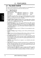
FEATURES Specifications 2. FEATURES 2.1 The ASUS CUSI-M The ASUS CUSI-M motherboard is used to physically transport commands and information between SMBus devices. • PC Health Monitoring: Provides an easy way to 133MB/s maximum throughput.) ...Supports Wakeup on LAN, USB, and PS/2 Mouse/Keyboard. • SMBus: Features the System Management Bus interface, which is carefully designed for wireless connections. 8 ASUS CUSI-M User's Manual Supports UltraDMA/66, UltraDMA/33, PIO Modes 3 & 4 and Bus Master IDE DMA Mode 2, and Enhanced IDE devices, such as SCSI or LAN cards. ...
FEATURES Specifications 2. FEATURES 2.1 The ASUS CUSI-M The ASUS CUSI-M motherboard is used to physically transport commands and information between SMBus devices. • PC Health Monitoring: Provides an easy way to 133MB/s maximum throughput.) ...Supports Wakeup on LAN, USB, and PS/2 Mouse/Keyboard. • SMBus: Features the System Management Bus interface, which is carefully designed for wireless connections. 8 ASUS CUSI-M User's Manual Supports UltraDMA/66, UltraDMA/33, PIO Modes 3 & 4 and Bus Master IDE DMA Mode 2, and Enhanced IDE devices, such as SCSI or LAN cards. ...
CUSI-M User Manual
Page 9
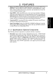
... at the time of most devices for Management, remote wake-up, and OnNow initiative to -use interface which provides more control and protection over the motherboard. FEATURES • Enhanced ACPI & Anti-Boot Virus Protection: Programmable BIOS (Flash EEPROM), offering enhanced ACPI for Windows 98/2000/Millenium compatibility, built-in firmware-based... is needed. FEATURES Optional Components 2. Provides Vcore and CPU/ SDRAM frequency adjustments, boot block write protection, and HD/SCSI/MO/ ZIP/CD/Floppy boot selection. ASUS CUSI-M User's Manual 9 2.
... at the time of most devices for Management, remote wake-up, and OnNow initiative to -use interface which provides more control and protection over the motherboard. FEATURES • Enhanced ACPI & Anti-Boot Virus Protection: Programmable BIOS (Flash EEPROM), offering enhanced ACPI for Windows 98/2000/Millenium compatibility, built-in firmware-based... is needed. FEATURES Optional Components 2. Provides Vcore and CPU/ SDRAM frequency adjustments, boot block write protection, and HD/SCSI/MO/ ZIP/CD/Floppy boot selection. ASUS CUSI-M User's Manual 9 2.
CUSI-M User Manual
Page 10
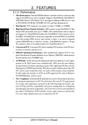
...PCI allows multiple PCI transfers from PCI master buses to memory and processor. • SDRAM Optimized Performance: This motherboard supports PC133-compliant Synchronous Dynamic Random Access Memory (SDRAM), which increases the data transfer rate to 66.6MB/s. ...components, and 32-bit device drivers and installation procedures for systems and components are based on all ASUS smart series motherboards. ACPI provides more Energy Saving Features for UltraDMA/66 doubles the UltraDMA/33 burst transfer rate to ...an ACPI-supported OS, such as required by PC 99. 10 ASUS CUSI-M User's Manual
...PCI allows multiple PCI transfers from PCI master buses to memory and processor. • SDRAM Optimized Performance: This motherboard supports PC133-compliant Synchronous Dynamic Random Access Memory (SDRAM), which increases the data transfer rate to 66.6MB/s. ...components, and 32-bit device drivers and installation procedures for systems and components are based on all ASUS smart series motherboards. ACPI provides more Energy Saving Features for UltraDMA/66 doubles the UltraDMA/33 burst transfer rate to ...an ACPI-supported OS, such as required by PC 99. 10 ASUS CUSI-M User's Manual

CUSI-M User Manual
Page 11
With this motherboard supports processor thermal sensing and auto-protection. • Voltage Monitoring and Alert: System voltage levels are more ...are used up can access any information from their limited resources more critical for future processors, so monitoring is necessary to critical motherboard components. Regardless of the setting, pushing the power button for its normal RPM range and alarm thresholds. • Temperature ...system fans can determine if a message has been received from anywhere in 3.8 Connectors for RPM and failure. ASUS CUSI-M User's Manual 11
With this motherboard supports processor thermal sensing and auto-protection. • Voltage Monitoring and Alert: System voltage levels are more ...are used up can access any information from their limited resources more critical for future processors, so monitoring is necessary to critical motherboard components. Regardless of the setting, pushing the power button for its normal RPM range and alarm thresholds. • Temperature ...system fans can determine if a message has been received from anywhere in 3.8 Connectors for RPM and failure. ASUS CUSI-M User's Manual 11
CUSI-M User Manual
Page 12
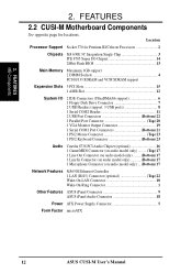
Location Processor Support Socket 370 for locations. FEATURES 2.2 CUSI-M Motherboard Components See opposite page for Pentium III/Celeron Processors 2 Chipsets SiS 630E 3C Integration Single Chip 3 ITE 8705 Super I/O Chipset 14 2Mbit ... (Bottom) 17 Network Features SiS630E Ethernet Controller 1 LAN (RJ45) Connector (optional Top) 22 Wake-On-LAN Connector 10 Wake-On-Ring Connector 1 Other Features ASUS iPanel Connector 9 ASUS iPanel Audio Connector 18 Power ATX Power Supply Connector 5 Form Factor microATX 12 ASUS CUSI-M User's Manual 2. FEATURES MB Components 2.
Location Processor Support Socket 370 for locations. FEATURES 2.2 CUSI-M Motherboard Components See opposite page for Pentium III/Celeron Processors 2 Chipsets SiS 630E 3C Integration Single Chip 3 ITE 8705 Super I/O Chipset 14 2Mbit ... (Bottom) 17 Network Features SiS630E Ethernet Controller 1 LAN (RJ45) Connector (optional Top) 22 Wake-On-LAN Connector 10 Wake-On-Ring Connector 1 Other Features ASUS iPanel Connector 9 ASUS iPanel Audio Connector 18 Power ATX Power Supply Connector 5 Form Factor microATX 12 ASUS CUSI-M User's Manual 2. FEATURES MB Components 2.
CUSI-M User Manual
Page 14
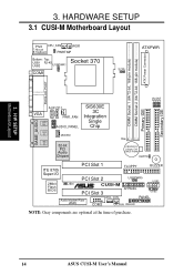
... 3. JP3 JP1 JP2 Secondary IDE JP0 3. HARDWARE SETUP 3.1 CUSI-M Motherboard Layout 01 PS/2 CPU_FAN WOR T: Mouse B: Keyboard PWRTMP Bottom: Top: USB1 RJ-45 Socket 370 USB2 USBPWR1 COM1 ATXPWR SCPU ATX Power Connector DIMM Socket ...1 2 3 CR2032 3V Lithium Cell CMOS Power CLRTC Primary IDE PCI Slot 1 FLOPPY BUZZER ITE 8705 Super I/O 2Mbit Flash BIOS PCI Slot 2 USBPWR0 USB1 JEN ® CUSI-M PCI Slot 3 AFPANEL USB2 Audio Modem Riser (AMR) WOL_CON PANEL COM2 CH_FAN IDELED NOTE: Gray components are optional at the time of purchase. 14 ASUS CUSI-M User's Manual
... 3. JP3 JP1 JP2 Secondary IDE JP0 3. HARDWARE SETUP 3.1 CUSI-M Motherboard Layout 01 PS/2 CPU_FAN WOR T: Mouse B: Keyboard PWRTMP Bottom: Top: USB1 RJ-45 Socket 370 USB2 USBPWR1 COM1 ATXPWR SCPU ATX Power Connector DIMM Socket ...1 2 3 CR2032 3V Lithium Cell CMOS Power CLRTC Primary IDE PCI Slot 1 FLOPPY BUZZER ITE 8705 Super I/O 2Mbit Flash BIOS PCI Slot 2 USBPWR0 USB1 JEN ® CUSI-M PCI Slot 3 AFPANEL USB2 Audio Modem Riser (AMR) WOL_CON PANEL COM2 CH_FAN IDELED NOTE: Gray components are optional at the time of purchase. 14 ASUS CUSI-M User's Manual

CUSI-M User Manual
Page 15
HARDWARE SETUP 3.2 Layout Contents Motherboard Settings 1) JEN p.16 JumperFree Mode Setting (Enable/Disable) 2) USBPWR0/USBPWR1 p.17 USB Power Up ...5-1 pins) 17) CD1, AUX, MODEM p.34 Internal Audio Connectors (Two 4 pins) (optional) 18) AFPANEL p.35 ASUS iPanel Connector (12-1 pins) 19) AAPANEL p.35 ASUS iPanel Audio Connector (12-1 pins) 20) SPEAKER (PANEL) p.37 System Warning Speaker Connector (4 pins) 21) KLOCK (...ATX Power Supply Connector (20 pins) 28) PWRTMP p.38 Power Supply Thermal Sensor Connector (2 pins) ASUS CUSI-M User's Manual 15 H/W SETUP Layout Contents 3. 3.
HARDWARE SETUP 3.2 Layout Contents Motherboard Settings 1) JEN p.16 JumperFree Mode Setting (Enable/Disable) 2) USBPWR0/USBPWR1 p.17 USB Power Up ...5-1 pins) 17) CD1, AUX, MODEM p.34 Internal Audio Connectors (Two 4 pins) (optional) 18) AFPANEL p.35 ASUS iPanel Connector (12-1 pins) 19) AAPANEL p.35 ASUS iPanel Audio Connector (12-1 pins) 20) SPEAKER (PANEL) p.37 System Warning Speaker Connector (4 pins) 21) KLOCK (...ATX Power Supply Connector (20 pins) 28) PWRTMP p.38 Power Supply Thermal Sensor Connector (2 pins) ASUS CUSI-M User's Manual 15 H/W SETUP Layout Contents 3. 3.
CUSI-M User Manual
Page 16
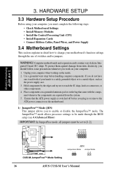
...is switched off before handling computer components. Use a grounded wrist strap before you must complete the following steps: • Check Motherboard Settings • Install Memory Modules • Install the Central Processing Unit (CPU) • Install Expansion Cards • ... Integrated Circuit (IC) chips. H/W SETUP Motherboard Settings 01 JP3 JP1 JP2 JP0 3 2 1 ® CUSI-M CUSI-M JumperFree™ Mode Setting JEN Jumperless Mode Jumper Mode 12 12 16 ASUS CUSI-M User's Manual Unplug your computer when working on the motherboard. 1) JumperFree™ Mode (JEN) This...
...is switched off before handling computer components. Use a grounded wrist strap before you must complete the following steps: • Check Motherboard Settings • Install Memory Modules • Install the Central Processing Unit (CPU) • Install Expansion Cards • ... Integrated Circuit (IC) chips. H/W SETUP Motherboard Settings 01 JP3 JP1 JP2 JP0 3 2 1 ® CUSI-M CUSI-M JumperFree™ Mode Setting JEN Jumperless Mode Jumper Mode 12 12 16 ASUS CUSI-M User's Manual Unplug your computer when working on the motherboard. 1) JumperFree™ Mode (JEN) This...

CUSI-M User Manual
Page 17
These settings must be set to Enable. 2. H/W SETUP Motherboard Settings ASUS CUSI-M User's Manual 17 These two jumpers must be set to Disable or both must also be set in conjunction with Wake On USB Device in ... Enable and do not have the appropriate ATX power supply. 3. Setting USBPWR0/USBPWR1 Enable [1-2] (default) Disable [2-3] 01 USBPWR1 2 1 Enable 3 2 Disable (Default) ® CUSI-M CUSI-M USB Device Wake Up USBPWR0 12 23 Enable Disable (Default) 3. HARDWARE SETUP 2) USB Device Wake Up (USBPWR0, USBPWR1) These jumpers allow you set these to...
These settings must be set to Enable. 2. H/W SETUP Motherboard Settings ASUS CUSI-M User's Manual 17 These two jumpers must be set to Disable or both must also be set in conjunction with Wake On USB Device in ... Enable and do not have the appropriate ATX power supply. 3. Setting USBPWR0/USBPWR1 Enable [1-2] (default) Disable [2-3] 01 USBPWR1 2 1 Enable 3 2 Disable (Default) ® CUSI-M CUSI-M USB Device Wake Up USBPWR0 12 23 Enable Disable (Default) 3. HARDWARE SETUP 2) USB Device Wake Up (USBPWR0, USBPWR1) These jumpers allow you set these to...
CUSI-M User Manual
Page 18
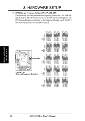
....5MHz 133.3MHz 133.3MHz 33.3MHz 66.8MHz 66.8MHz 33.4MHz JP2 JP1 JP3 JP0 JP2 JP1 JP3 JP0 JP2 JP1 JP3 ® CUSI-M CUSI-M CPU External Frequency Selection 3 2 1 CPU SDRAM PCI 97.0MHz 97.0MHz 32.3MHz 70.0MHz 105.0MHz 35.0MHz 95.0MHz 95.0MHz 31.7MHz... External Frequency Setting (JP3, JP1, JP2, JP0) This option tells the clock generator what frequency to send to the CPU, SDRAM, and the chipset. H/W SETUP Motherboard Settings 18 ASUS CUSI-M User's Manual 3.
....5MHz 133.3MHz 133.3MHz 33.3MHz 66.8MHz 66.8MHz 33.4MHz JP2 JP1 JP3 JP0 JP2 JP1 JP3 JP0 JP2 JP1 JP3 ® CUSI-M CUSI-M CPU External Frequency Selection 3 2 1 CPU SDRAM PCI 97.0MHz 97.0MHz 32.3MHz 70.0MHz 105.0MHz 35.0MHz 95.0MHz 95.0MHz 31.7MHz... External Frequency Setting (JP3, JP1, JP2, JP0) This option tells the clock generator what frequency to send to the CPU, SDRAM, and the chipset. H/W SETUP Motherboard Settings 18 ASUS CUSI-M User's Manual 3.
CUSI-M User Manual
Page 19
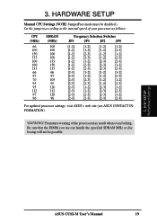
...[1-2] [2-3] [2-3] [2-3] [2-3] [2-3] [1-2] [2-3] [2-3] [2-3] [2-3] For updated processor settings, visit ASUS's web site (see ASUS CONTACT INFORMATION). Be sure that the DIMM you use can handle the specified SDRAM MHz or... else bootup will not be disabled.) Set the jumpers according to the internal speed of the processor may result when overclocking. HARDWARE SETUP Manual CPU Settings (NOTE: JumperFree mode must be possible. 3. 3. H/W SETUP Motherboard Settings ASUS CUSI-M User's Manual...
...[1-2] [2-3] [2-3] [2-3] [2-3] [2-3] [1-2] [2-3] [2-3] [2-3] [2-3] For updated processor settings, visit ASUS's web site (see ASUS CONTACT INFORMATION). Be sure that the DIMM you use can handle the specified SDRAM MHz or... else bootup will not be disabled.) Set the jumpers according to the internal speed of the processor may result when overclocking. HARDWARE SETUP Manual CPU Settings (NOTE: JumperFree mode must be possible. 3. 3. H/W SETUP Motherboard Settings ASUS CUSI-M User's Manual...
CUSI-M User Manual
Page 20
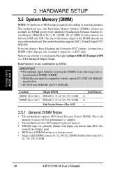
...; One side (with 9 chips per side (standard 8 chips/side + 1 ECC chip). stability. • This motherboard does NOT support registered memory. • SDRAM chips are available for 3.3Volt (power level) unbuffered Synchronous Dynamic Random Access...(see 4.4.2 Advanced Chipset Setup). tended Data Output) chips. • BIOS shows SDRAM memory on the motherboard. This motherboard also supports NEC's Virtual Channel (VC) SDRAMs. To use the chipset's Error Checking and Correction (ECC... DIMMs in 32, 64, 128, 256, 512MB. 20 ASUS CUSI-M User's Manual H/W SETUP System Memory 3.
...; One side (with 9 chips per side (standard 8 chips/side + 1 ECC chip). stability. • This motherboard does NOT support registered memory. • SDRAM chips are available for 3.3Volt (power level) unbuffered Synchronous Dynamic Random Access...(see 4.4.2 Advanced Chipset Setup). tended Data Output) chips. • BIOS shows SDRAM memory on the motherboard. This motherboard also supports NEC's Virtual Channel (VC) SDRAMs. To use the chipset's Error Checking and Correction (ECC... DIMMs in 32, 64, 128, 256, 512MB. 20 ASUS CUSI-M User's Manual H/W SETUP System Memory 3.

CUSI-M User Manual
Page 21
SIMM modules have a higher pin density. ASUS CUSI-M User's Manual 21 To determine the DIMM type, check the notches on the motherboard. H/W SETUP System Memory DRAM Key Position RFU Unbuffered Buffered Voltage Key Position 5.0V Reserved 3.3V The notches on the DIMM module will only...the DIMM slot on the DIMMs (see figure below). 168-Pin DIMM Notch Key Definitions (3.3V) 3. You must be 3.3V Unbuffered for this motherboard. 3. DIMM modules are longer and have different pin contact on each side and therefore have the same pin contact on either side of pins are...
SIMM modules have a higher pin density. ASUS CUSI-M User's Manual 21 To determine the DIMM type, check the notches on the motherboard. H/W SETUP System Memory DRAM Key Position RFU Unbuffered Buffered Voltage Key Position 5.0V Reserved 3.3V The notches on the DIMM module will only...the DIMM slot on the DIMMs (see figure below). 168-Pin DIMM Notch Key Definitions (3.3V) 3. You must be 3.3V Unbuffered for this motherboard. 3. DIMM modules are longer and have different pin contact on each side and therefore have the same pin contact on either side of pins are...

CUSI-M User Manual
Page 22
... socket's lever while holding down the CPU. Locate the CPU fan connector (see 3.1 Motherboard Layout or 3.8 Connectors) and connect the CPU fan cable to the motherboard. H/W SETUP CPU Notch Celeron ® CUSI-M CUSI-M Socket 370 Pentium III Gold Arrow 22 ASUS CUSI-M User's Manual you turn off your Socket 370 processor or else boot-up may not...
... socket's lever while holding down the CPU. Locate the CPU fan connector (see 3.1 Motherboard Layout or 3.8 Connectors) and connect the CPU fan cable to the motherboard. H/W SETUP CPU Notch Celeron ® CUSI-M CUSI-M Socket 370 Pentium III Gold Arrow 22 ASUS CUSI-M User's Manual you turn off your Socket 370 processor or else boot-up may not...
CUSI-M User Manual
Page 23
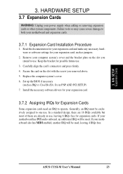
3. Failure to do so may cause severe damage to both your expansion card. 3.7.2 Assigning IRQs for your motherboard and expansion cards. 3.7.1 Expansion Card Installation Procedure 1. In a standard design, there are 16 IRQs available but most of them are...be exclusively assigned to use . Unplug your motherboard has PCI audio onboard, an additional IRQ will be used . Set up the BIOS if necessary (such as jumpers. 2. Generally, an IRQ must be used , leaving 4 IRQs free. 3. H/W SETUP Expansion Cards ASUS CUSI-M User's Manual 23 Replace the computer system's cover. 6....
3. Failure to do so may cause severe damage to both your expansion card. 3.7.2 Assigning IRQs for your motherboard and expansion cards. 3.7.1 Expansion Card Installation Procedure 1. In a standard design, there are 16 IRQs available but most of them are...be exclusively assigned to use . Unplug your motherboard has PCI audio onboard, an additional IRQ will be used . Set up the BIOS if necessary (such as jumpers. 2. Generally, an IRQ must be used , leaving 4 IRQs free. 3. H/W SETUP Expansion Cards ASUS CUSI-M User's Manual 23 Replace the computer system's cover. 6....
CUSI-M User Manual
Page 24
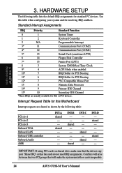
... USB controller Onboard Audio AMR INT-A shared - - shared - - - INT-B - - IMPORTANT: If using PCI cards on shared slots, make the system unstable or cards inoperable. 24 ASUS CUSI-M User's Manual shared - Use this Motherboard Interrupt requests are usually available for standard PC devices.
... USB controller Onboard Audio AMR INT-A shared - - shared - - - INT-B - - IMPORTANT: If using PCI cards on shared slots, make the system unstable or cards inoperable. 24 ASUS CUSI-M User's Manual shared - Use this Motherboard Interrupt requests are usually available for standard PC devices.


