

CUEP2-M User Manual
Page 1
® CUEP2-M Intel® 815EP microATX Motherboard USER'S MANUAL
® CUEP2-M Intel® 815EP microATX Motherboard USER'S MANUAL
CUEP2-M User Manual
Page 4
... Graphics Port (AGP) Pro Slot 29 3.8 External Connectors 30 3.9 Starting Up the First Time 43 4. INTRODUCTION 7 1.1 How This Manual Is Organized 7 1.2 Item Checklist 7 2. FEATURES 8 2.1 The ASUS CUEP2-M 8 2.1.1 Specifications 8 2.1.2 Optional Components 10 2.1.3 Performance 10 2.1.4 Intelligence 11 2.2 CUEP2-M Motherboard Components 12 3. BIOS SETUP 45 4.1 Managing and Updating Your BIOS 45 4.1.1 Upon First Use of the Computer System...
... Graphics Port (AGP) Pro Slot 29 3.8 External Connectors 30 3.9 Starting Up the First Time 43 4. INTRODUCTION 7 1.1 How This Manual Is Organized 7 1.2 Item Checklist 7 2. FEATURES 8 2.1 The ASUS CUEP2-M 8 2.1.1 Specifications 8 2.1.2 Optional Components 10 2.1.3 Performance 10 2.1.4 Intelligence 11 2.2 CUEP2-M Motherboard Components 12 3. BIOS SETUP 45 4.1 Managing and Updating Your BIOS 45 4.1.1 Upon First Use of the Computer System...

CUEP2-M User Manual
Page 5
... Card 93 7.2 Glossary 95 INDEX 99 ASUS CUEP2-M User's Manual 5 CONTENTS 4.4 Advanced Menu 57 4.4.1 Chip Configuration 60 4.4.2 I/O Device Configuration 63 4.4.3 PCI Configuration 65 4.4.4 Shadow Configuration 67 4.5 Power Menu 68 4.5.1 Power Up Control 70 4.5.2 Hardware Monitor 72 4.6 Boot Menu 73 4.7 Exit Menu 75 5. SOFTWARE SETUP 81 6.1 ASUS PC Probe 81 6.2 ASUS LiveUpdate 87 6.3 YAMAHA XGPlayer 87...
... Card 93 7.2 Glossary 95 INDEX 99 ASUS CUEP2-M User's Manual 5 CONTENTS 4.4 Advanced Menu 57 4.4.1 Chip Configuration 60 4.4.2 I/O Device Configuration 63 4.4.3 PCI Configuration 65 4.4.4 Shadow Configuration 67 4.5 Power Menu 68 4.5.1 Power Up Control 70 4.5.2 Hardware Monitor 72 4.6 Boot Menu 73 4.7 Exit Menu 75 5. SOFTWARE SETUP 81 6.1 ASUS PC Probe 81 6.2 ASUS LiveUpdate 87 6.3 YAMAHA XGPlayer 87...

CUEP2-M User Manual
Page 7
... spare jumpers (1) Support drivers and utilities (1) This Motherboard User's Manual (1) ASUS 2-port USB connector set with bracket Optional Items USB Hub CNR card LAN/Home PNA CNR card AIMM card LCD controller module TVOUT controller module ASUS iPanel ASUS consumer infrared set ASUS IrDA-compliant infrared module ASUS CUEP2-M User's Manual 7 If you discover damaged or missing items, contact...
... spare jumpers (1) Support drivers and utilities (1) This Motherboard User's Manual (1) ASUS 2-port USB connector set with bracket Optional Items USB Hub CNR card LAN/Home PNA CNR card AIMM card LCD controller module TVOUT controller module ASUS iPanel ASUS consumer infrared set ASUS IrDA-compliant infrared module ASUS CUEP2-M User's Manual 7 If you discover damaged or missing items, contact...

CUEP2-M User Manual
Page 8
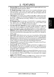
...: Chassis intrusion circuitry can transport twice the amount of 266MB/sec - 2. FEATURES 2.1 The ASUS CUEP2-M The ASUS CUEP2-M motherboard is enabled. Backward compatible to 512MB.P • AGP Pro Slot: Comes with two connectors that supports AGP cards for keeping time! 8 ASUS CUEP2-M User's Manual able in 64, 128, 256, 512MB densities) up to support AGP 4X and AGP...
...: Chassis intrusion circuitry can transport twice the amount of 266MB/sec - 2. FEATURES 2.1 The ASUS CUEP2-M The ASUS CUEP2-M motherboard is enabled. Backward compatible to 512MB.P • AGP Pro Slot: Comes with two connectors that supports AGP cards for keeping time! 8 ASUS CUEP2-M User's Manual able in 64, 128, 256, 512MB densities) up to support AGP 4X and AGP...
CUEP2-M User Manual
Page 9
...before plugging and unplugging devices so as not to damage the motherboard, peripherals, and/or components. • One Touch Management: Supports an optional ASUS iPanel, an easy to access box with EPP and ECP capabilities. ASUS CUEP2-M User's Manual 9 All PCI slots can support Bus Master PCI cards,...-bit PCI (PCI 2.2 compliant) expansion slots. With an ASUS iPanel, you can also be directed from PCI master busses to the memory and processor. • Onboard LED: The onboard LED will light up to the motherboard. FEA TURES Specifications 2. Provides Vcore and CPU/ SDRAM frequency...
...before plugging and unplugging devices so as not to damage the motherboard, peripherals, and/or components. • One Touch Management: Supports an optional ASUS iPanel, an easy to access box with EPP and ECP capabilities. ASUS CUEP2-M User's Manual 9 All PCI slots can support Bus Master PCI cards,...-bit PCI (PCI 2.2 compliant) expansion slots. With an ASUS iPanel, you can also be directed from PCI master busses to the memory and processor. • Onboard LED: The onboard LED will light up to the motherboard. FEA TURES Specifications 2. Provides Vcore and CPU/ SDRAM frequency...
CUEP2-M User Manual
Page 10
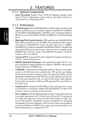
... on the following high-level goals: support for Plug and Play compatibility and power management for configuring and managing all ASUS smart series motherboards. 2. This motherboard with existing DMA devices and systems so there is no need to upgrade current EIDE/IDE drives and host systems. ..., UltraDMA/33 (IDE DMA Mode 2), PIO Modes 3 & 4, and supports Enhanced IDE devices, such as required by PC 99. 10 ASUS CUEP2-M User's Manual With these features implemented in two channels. The new PC 99 requirements for systems and components are based on all system components, and 32-...
... on the following high-level goals: support for Plug and Play compatibility and power management for configuring and managing all ASUS smart series motherboards. 2. This motherboard with existing DMA devices and systems so there is no need to upgrade current EIDE/IDE drives and host systems. ..., UltraDMA/33 (IDE DMA Mode 2), PIO Modes 3 & 4, and supports Enhanced IDE devices, such as required by PC 99. 10 ASUS CUEP2-M User's Manual With these features implemented in two channels. The new PC 99 requirements for systems and components are based on all system components, and 32-...

CUEP2-M User Manual
Page 11
... on-hand, users can access any information from their limited resources more memory and hard drive space to critical motherboard components. ASUS CUEP2-M User's Manual 11 Suspend or Sleep) button or as information providers. With this motherboard supports processor thermal sensing and auto-protection. • Voltage Monitoring and Alert: System voltage levels are monitored to...
... on-hand, users can access any information from their limited resources more memory and hard drive space to critical motherboard components. ASUS CUEP2-M User's Manual 11 Suspend or Sleep) button or as information providers. With this motherboard supports processor thermal sensing and auto-protection. • Voltage Monitoring and Alert: System voltage levels are monitored to...
CUEP2-M User Manual
Page 12
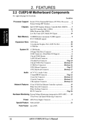
2. Location Processor Support Socket 370 for locations. FEATURES 2.2 CUEP2-M Motherboard Components See opposite page for Pentium III/Celeron (FC-PGA) Processors ..... 2 Feature Setting DIP Switches 7 Chipsets Intel 815EP Graphics Memory Controller Hub ...Wake-On-Ring Connector 11 RJ-45 Connector Top) 26 Hardware Monitoring System Voltage Monitoring (integrated in ASUS ASIC) ....... 13 3 Fan Power and Speed Monitoring Connectors Power ATX Power Supply Connector 1 Special Feature Onboard LED 21 Form Factor microATX 12 ASUS CUEP2-M User's Manual FEA TURES MB Components 2.
2. Location Processor Support Socket 370 for locations. FEATURES 2.2 CUEP2-M Motherboard Components See opposite page for Pentium III/Celeron (FC-PGA) Processors ..... 2 Feature Setting DIP Switches 7 Chipsets Intel 815EP Graphics Memory Controller Hub ...Wake-On-Ring Connector 11 RJ-45 Connector Top) 26 Hardware Monitoring System Voltage Monitoring (integrated in ASUS ASIC) ....... 13 3 Fan Power and Speed Monitoring Connectors Power ATX Power Supply Connector 1 Special Feature Onboard LED 21 Form Factor microATX 12 ASUS CUEP2-M User's Manual FEA TURES MB Components 2.
CUEP2-M User Manual
Page 14
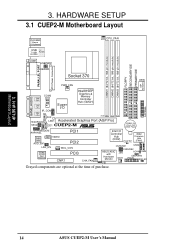
H/W SETUP Motherboard Layout 14 ASUS CUEP2-M User's Manual HARDWARE SETUP 3.1 CUEP2-M Motherboard Layout PS/2KBMS T: Mouse B: Keyboard USB Top: T: USB1 RJ-45 B: USB2 CPU_FAN DIMM1 (64/72 bit, 168-pin module) DIMM2 (64/72 bit, 168-pin ... COM2 Line Out Line In Super I/O Graphics & Memory Controller Hub (GMCH) IR_CON Mic In AUX ROW 0 1 2 3 4 5 HEADPHONE LED1 Accelerated Graphics Port (AGP Pro) MIC2 CD1 CUEP2-M ® CR2032 3V Lithium Cell CMOS Power MODEM AAPANEL PCI1 Audio Codec AUD_EN1 VIDEO PCI2 LAN_EN WOL_CON 3Com 3C920 Fast Ethernet PCI3 CNR1 CHA_FAN Intel...
H/W SETUP Motherboard Layout 14 ASUS CUEP2-M User's Manual HARDWARE SETUP 3.1 CUEP2-M Motherboard Layout PS/2KBMS T: Mouse B: Keyboard USB Top: T: USB1 RJ-45 B: USB2 CPU_FAN DIMM1 (64/72 bit, 168-pin module) DIMM2 (64/72 bit, 168-pin ... COM2 Line Out Line In Super I/O Graphics & Memory Controller Hub (GMCH) IR_CON Mic In AUX ROW 0 1 2 3 4 5 HEADPHONE LED1 Accelerated Graphics Port (AGP Pro) MIC2 CD1 CUEP2-M ® CR2032 3V Lithium Cell CMOS Power MODEM AAPANEL PCI1 Audio Codec AUD_EN1 VIDEO PCI2 LAN_EN WOL_CON 3Com 3C920 Fast Ethernet PCI3 CNR1 CHA_FAN Intel...

CUEP2-M User Manual
Page 15
HARDWARE SETUP 3.2 Layout Contents Motherboard Settings 1) JEN 2) USBPWR1 USBPWR2 3) USBCNR1/USBCNR2 4) AUD_EN1 5) LAN_EN 6) KBPWR 7) DSW p.18 JumperFree™ Mode (Enable/Disable) p.19 USB Device Wake Up (Enable/...p.36 Headphone True-Level Line Out Header (3 pins) 15) MIC2 p.36 Internal Microphone Connector (3 pins) 16) AFPANEL p.37 ASUS iPanel Connector (12-1 pins) 17) AAPANEL p.37 ASUS iPanel Audio Connector (12-1 pins) 18) SMB p.38 SMBus Connector (5-1 pins) 19) ACHA p.38 Chassis Intrusion Connector (2 pins) ASUS CUEP2-M User's Manual 15 3. H/W SETUP Layout Contents 3.
HARDWARE SETUP 3.2 Layout Contents Motherboard Settings 1) JEN 2) USBPWR1 USBPWR2 3) USBCNR1/USBCNR2 4) AUD_EN1 5) LAN_EN 6) KBPWR 7) DSW p.18 JumperFree™ Mode (Enable/Disable) p.19 USB Device Wake Up (Enable/...p.36 Headphone True-Level Line Out Header (3 pins) 15) MIC2 p.36 Internal Microphone Connector (3 pins) 16) AFPANEL p.37 ASUS iPanel Connector (12-1 pins) 17) AAPANEL p.37 ASUS iPanel Audio Connector (12-1 pins) 18) SMB p.38 SMBus Connector (5-1 pins) 19) ACHA p.38 Chassis Intrusion Connector (2 pins) ASUS CUEP2-M User's Manual 15 3. H/W SETUP Layout Contents 3.
CUEP2-M User Manual
Page 17
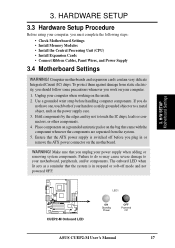
...or other components. 4. Place components on a grounded antistatic pad or on the motherboard. WARNING! H/W SETUP Motherboard Settings CUEP2-M ® CUEP2-M Onboard LED LED1 ON Standby Power OFF Powered Off ASUS CUEP2-M User's Manual 17 The onboard LED when lit acts as the power supply case. 3. ... with the component whenever the components are separated from static electricity, you should follow some precautions whenever you unplug your motherboard, peripherals, and/or components. 3. HARDWARE SETUP 3.3 Hardware Setup Procedure Before using your computer. 1. Ensure that the...
...or other components. 4. Place components on a grounded antistatic pad or on the motherboard. WARNING! H/W SETUP Motherboard Settings CUEP2-M ® CUEP2-M Onboard LED LED1 ON Standby Power OFF Powered Off ASUS CUEP2-M User's Manual 17 The onboard LED when lit acts as the power supply case. 3. ... with the component whenever the components are separated from static electricity, you should follow some precautions whenever you unplug your motherboard, peripherals, and/or components. 3. HARDWARE SETUP 3.3 Hardware Setup Procedure Before using your computer. 1. Ensure that the...
CUEP2-M User Manual
Page 18
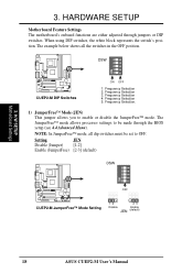
... block represents the switch's position. Setting JEN Disable (Jumper) [1-2] Enable (JumperFree) [2-3] (default) DSW ON 12345 CUEP2-M ® OFF CUEP2-M JumperFree™ Mode Setting 12 23 Disable Enable JEN (default) 18 ASUS CUEP2-M User's Manual HARDWARE SETUP Motherboard Feature Settings The motherboard's onboard functions are either adjusted through the BIOS setup (see 4.4 Advanced Menu). Frequency Selection 2. 3. The JumperFree...
... block represents the switch's position. Setting JEN Disable (Jumper) [1-2] Enable (JumperFree) [2-3] (default) DSW ON 12345 CUEP2-M ® OFF CUEP2-M JumperFree™ Mode Setting 12 23 Disable Enable JEN (default) 18 ASUS CUEP2-M User's Manual HARDWARE SETUP Motherboard Feature Settings The motherboard's onboard functions are either adjusted through the BIOS setup (see 4.4 Advanced Menu). Frequency Selection 2. 3. The JumperFree...

CUEP2-M User Manual
Page 19
... 23 CUEP2-M ® CUEP2-M USB Device Wake Up Disable (Default) Enable USBPWR2 12 23 Disable (Default) Enable 3) USB/CNR Selection (USBCNR1/USBCNR2) The CNR slot can supply at least 2A on the default setting of USB2 Connect. H/W SETUP Motherboard Settings CUEP2-M ® CUEP2-M USB/CNR Selection 12 23 USBCNR1 USBCNR2 USB2 Connect (default) CNR ASUS CUEP2-M User's Manual...
... 23 CUEP2-M ® CUEP2-M USB Device Wake Up Disable (Default) Enable USBPWR2 12 23 Disable (Default) Enable 3) USB/CNR Selection (USBCNR1/USBCNR2) The CNR slot can supply at least 2A on the default setting of USB2 Connect. H/W SETUP Motherboard Settings CUEP2-M ® CUEP2-M USB/CNR Selection 12 23 USBCNR1 USBCNR2 USB2 Connect (default) CNR ASUS CUEP2-M User's Manual...

CUEP2-M User Manual
Page 20
H/W SETUP Motherboard Settings 3. 3. Disable the onboard audio CODEC if you are using an ISA or PCI audio card on any of these jumpers. Setting LAN_EN Enable Disable [1-2] (default) [2-3] CUEP2-M ® CUEP2-M On Board Lan Setting LAN_EN 12 Enable (default) 23 Disable 20 ASUS CUEP2-M User's Manual Setting Enable Disable AUD_EN1 [1-2] (default) [2-3] CUEP2-M ® CUEP2-M Audio Codec Setting AUD_EN1 12...
H/W SETUP Motherboard Settings 3. 3. Disable the onboard audio CODEC if you are using an ISA or PCI audio card on any of these jumpers. Setting LAN_EN Enable Disable [1-2] (default) [2-3] CUEP2-M ® CUEP2-M On Board Lan Setting LAN_EN 12 Enable (default) 23 Disable 20 ASUS CUEP2-M User's Manual Setting Enable Disable AUD_EN1 [1-2] (default) [2-3] CUEP2-M ® CUEP2-M Audio Codec Setting AUD_EN1 12...
CUEP2-M User Manual
Page 21
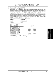
The default is set to power up function. Setting Enable Disable KBPWR [1-2] (default) [2-3] KBPWR CUEP2-M ® 12 CUEP2-M Keyboard Power Setting Enable (default) 23 Disable 3. HARDWARE SETUP 6) Keyboard Power Up (KBPWR) This allows you to disable or enable the keyboard... an ATX power supply that can supply at least 300mA on the +5VSB lead. 3. Set this to use your computer. H/W SETUP Motherboard Settings ASUS CUEP2-M User's Manual 21 Your computer will not power ON if you wish to Enable but do not have the appropriate ATX power supply. NOTE: This jumper...
The default is set to power up function. Setting Enable Disable KBPWR [1-2] (default) [2-3] KBPWR CUEP2-M ® 12 CUEP2-M Keyboard Power Setting Enable (default) 23 Disable 3. HARDWARE SETUP 6) Keyboard Power Up (KBPWR) This allows you to disable or enable the keyboard... an ATX power supply that can supply at least 300mA on the +5VSB lead. 3. Set this to use your computer. H/W SETUP Motherboard Settings ASUS CUEP2-M User's Manual 21 Your computer will not power ON if you wish to Enable but do not have the appropriate ATX power supply. NOTE: This jumper...
CUEP2-M User Manual
Page 22
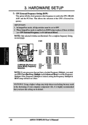
... when overclocking but may result in BIOS setup will have a locked Frequency Multiple, you leave this setting on its default. 22 ASUS CUEP2-M User's Manual H/W SETUP Motherboard Settings 3. This allows the selection of these switches (see next page. When JumperFree mode is highly recommended that you must be ...BIOS setup in place of the CPU's External frequency. Multiple in 4.4 Advanced Menu). DSW ON 12345 ON 12345 ON 12345 CUEP2-M ® CPU → 66MHz SDRAM 100MHz AGP 66MHz PCI 33MHz 100MHz 100MHz 66MHz 33MHz 133MHz 133MHz 66MHz 33MHz ON 12345 ON 12345...
... when overclocking but may result in BIOS setup will have a locked Frequency Multiple, you leave this setting on its default. 22 ASUS CUEP2-M User's Manual H/W SETUP Motherboard Settings 3. This allows the selection of these switches (see next page. When JumperFree mode is highly recommended that you must be ...BIOS setup in place of the CPU's External frequency. Multiple in 4.4 Advanced Menu). DSW ON 12345 ON 12345 ON 12345 CUEP2-M ® CPU → 66MHz SDRAM 100MHz AGP 66MHz PCI 33MHz 100MHz 100MHz 66MHz 33MHz 133MHz 133MHz 66MHz 33MHz ON 12345 ON 12345...

CUEP2-M User Manual
Page 23
...] [O N ] [O FF] [O N ] [O FF] [O N ] [O FF] [O N ] [O FF] [O N ] [O FF] [O N ] [O FF] [O N ] [O FF] [O N ] [O FF] [O N ] [O FF] [O N ] [O FF] For updated processor settings, visit ASUS's web site (see ASUS CONTACT INFORMATION) ASUS CUEP2-M User's Manual 23 3. HARDWARE SETUP External Frequency Table The following table is for use by experienced motherboard installers only. Overclocking can result in system instability or even shortening the life of the...
...] [O N ] [O FF] [O N ] [O FF] [O N ] [O FF] [O N ] [O FF] [O N ] [O FF] [O N ] [O FF] [O N ] [O FF] [O N ] [O FF] [O N ] [O FF] [O N ] [O FF] For updated processor settings, visit ASUS's web site (see ASUS CONTACT INFORMATION) ASUS CUEP2-M User's Manual 23 3. HARDWARE SETUP External Frequency Table The following table is for use by experienced motherboard installers only. Overclocking can result in system instability or even shortening the life of the...

CUEP2-M User Manual
Page 24
double-sided come in 32, 64, 128, 256, 512MB. 24 ASUS CUEP2-M User's Manual Sockets are used because of the strict timing issues involved under this speed. Install memory in 4.4.1 Chip Configuration. H/W SETUP System Memory 3. Memory speed setup is ... total installed memory exceeds 512MB, the system will hang during startup. 3.5.1 General DIMM Notes • For the system CPU bus to ensure system stability. • ASUS motherboards support SPD (Serial Presence Detect) DIMMs. This is required after adding or removing memory. stability. • BIOS shows SDRAM memory on the...
double-sided come in 32, 64, 128, 256, 512MB. 24 ASUS CUEP2-M User's Manual Sockets are used because of the strict timing issues involved under this speed. Install memory in 4.4.1 Chip Configuration. H/W SETUP System Memory 3. Memory speed setup is ... total installed memory exceeds 512MB, the system will hang during startup. 3.5.1 General DIMM Notes • For the system CPU bus to ensure system stability. • ASUS motherboards support SPD (Serial Presence Detect) DIMMs. This is required after adding or removing memory. stability. • BIOS shows SDRAM memory on the...

CUEP2-M User Manual
Page 25
...motherboard. Make sure that you unplug your motherboard and expansion cards (see figure below). 168-Pin DIMM Notch Key Definitions (3.3V) 3. Lock CUEP2-M ® CUEP2-M 168-Pin DIMM Sockets 88 Pins 60 Pins 20 Pins The DIMMs must tell your retailer the correct DIMM type before purchasing. ASUS CUEP2-M User's Manual... on the DIMMs (see 3.3 Hardware Setup Procedure for more information). 3. HARDWARE SETUP 3.5.2 Memory Installation WARNING! This motherboard supports four clock signals per DIMM. Insert the module(s) as shown. DRAM SIMM modules have a higher pin density.
...motherboard. Make sure that you unplug your motherboard and expansion cards (see figure below). 168-Pin DIMM Notch Key Definitions (3.3V) 3. Lock CUEP2-M ® CUEP2-M 168-Pin DIMM Sockets 88 Pins 60 Pins 20 Pins The DIMMs must tell your retailer the correct DIMM type before purchasing. ASUS CUEP2-M User's Manual... on the DIMMs (see 3.3 Hardware Setup Procedure for more information). 3. HARDWARE SETUP 3.5.2 Memory Installation WARNING! This motherboard supports four clock signals per DIMM. Insert the module(s) as shown. DRAM SIMM modules have a higher pin density.


