CS-B User's Manual
Page 1
CS-B Motherboard
CS-B Motherboard
CS-B User's Manual
Page 3
Contents Safety information iv About this guide iv Package contents vi CS-B specifications summary vi Chapter 1: Product introduction 1.1 Before you proceed 1-1 1.2 Motherboard overview 1-1 1.3 Central Processing Unit (CPU 1-3 1.4 System memory 1-7 1.5 Expansion slots 1-9 1.6 Jumpers 1-10 1.7 Connectors 1-11 1.8 Onboard LEDs 1-19 1.9 Software support 1-20 Chapter 2: BIOS information ... 2-10 2.5 Ai Tweaker menu 2-12 2.6 Advanced menu 2-22 2.7 Monitor menu 2-33 2.8 Boot menu 2-35 2.9 Tools menu 2-41 2.10 Exit menu 2-42 Appendices Notices...A-1 ASUS contact information A-3 iii
Contents Safety information iv About this guide iv Package contents vi CS-B specifications summary vi Chapter 1: Product introduction 1.1 Before you proceed 1-1 1.2 Motherboard overview 1-1 1.3 Central Processing Unit (CPU 1-3 1.4 System memory 1-7 1.5 Expansion slots 1-9 1.6 Jumpers 1-10 1.7 Connectors 1-11 1.8 Onboard LEDs 1-19 1.9 Software support 1-20 Chapter 2: BIOS information ... 2-10 2.5 Ai Tweaker menu 2-12 2.6 Advanced menu 2-22 2.7 Monitor menu 2-33 2.8 Boot menu 2-35 2.9 Tools menu 2-41 2.10 Exit menu 2-42 Appendices Notices...A-1 ASUS contact information A-3 iii
CS-B User's Manual
Page 4
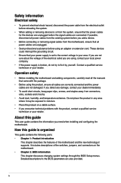
...service technician or your retailer. If you are not sure about the voltage of the electrical outlet you need when installing and configuring the motherboard. Do not place the product in your power supply is set to the correct voltage in any damage, contact your local power company....connectors on a stable surface. • If you detect any area where it may be exposed to moisture. • Place the product on the motherboard. • Chapter 2: BIOS information This chapter discusses changing system settings through the BIOS Setup menus. How this guide This user guide contains the ...
...service technician or your retailer. If you are not sure about the voltage of the electrical outlet you need when installing and configuring the motherboard. Do not place the product in your power supply is set to the correct voltage in any damage, contact your local power company....connectors on a stable surface. • If you detect any area where it may be exposed to moisture. • Place the product on the motherboard. • Chapter 2: BIOS information This chapter discusses changing system settings through the BIOS Setup menus. How this guide This user guide contains the ...

CS-B User's Manual
Page 6
resolution of 1920 x 1200 @60Hz - When a mini PCIe card is damaged or missing, contact your motherboard package for the following items. Motherboard Cables Accessories Application DVD Documentation ASUS CS-B motherboard 2 x Serial ATA 6.0 Gb/s cables 1 x I ports - CS-B specifications summary CPU Chipset Memory Graphics Expansion slots LGA1150 socket for Intel® 4th Generation Core™ i7 / i5 / i3, Pentium...
resolution of 1920 x 1200 @60Hz - When a mini PCIe card is damaged or missing, contact your motherboard package for the following items. Motherboard Cables Accessories Application DVD Documentation ASUS CS-B motherboard 2 x Serial ATA 6.0 Gb/s cables 1 x I ports - CS-B specifications summary CPU Chipset Memory Graphics Expansion slots LGA1150 socket for Intel® 4th Generation Core™ i7 / i5 / i3, Pentium...
CS-B User's Manual
Page 7
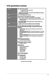
... Total ESD Guard: Strongest electrostatic protection for better thermal performance - Layout Design: Maximized microATX layout for maximum lifespan - CS-B specifications summary Storage LAN Audio USB ASUS unique features Intel® Q87 Express Chipset: - 5 x Serial ATA 6.0 Gb/s connectors - 1 x mSATA connector... at midboard, 2 ports at back panel) 8 x USB 2.0 ports (4 ports at midboard, 4 ports at back panel) Bespoke Motherboard Design & Commercial Focused Features: - Intel® I217LM Gigabit LAN controller Realtek RTL8111G-CG Gigabit LAN controller 8-channel Realtek® ALC887-VD...
... Total ESD Guard: Strongest electrostatic protection for better thermal performance - Layout Design: Maximized microATX layout for maximum lifespan - CS-B specifications summary Storage LAN Audio USB ASUS unique features Intel® Q87 Express Chipset: - 5 x Serial ATA 6.0 Gb/s connectors - 1 x mSATA connector... at midboard, 2 ports at back panel) 8 x USB 2.0 ports (4 ports at midboard, 4 ports at back panel) Bespoke Motherboard Design & Commercial Focused Features: - Intel® I217LM Gigabit LAN controller Realtek RTL8111G-CG Gigabit LAN controller 8-channel Realtek® ALC887-VD...

CS-B User's Manual
Page 9
... not overtighten the screws! Failure to do so can damage the motherboard. Doing so can cause you uninstall any component, ensure that the motherboard fits. Failure to do so may cause severe damage to the chassis. ASUS CS-B 1-1 The edge with the component. • Before you install... or remove any component, place it into the holes indicated by the edges to avoid touching the ICs on them. • Whenever you physical injury and damage to motherboard components. 1.2.1 Placement ...
... not overtighten the screws! Failure to do so can damage the motherboard. Doing so can cause you uninstall any component, ensure that the motherboard fits. Failure to do so may cause severe damage to the chassis. ASUS CS-B 1-1 The edge with the component. • Before you install... or remove any component, place it into the holes indicated by the edges to avoid touching the ICs on them. • Whenever you physical injury and damage to motherboard components. 1.2.1 Placement ...

CS-B User's Manual
Page 10
Place this side towards the rear of the chassis CS-B 1.2.3 Motherboard layout 12 3 1 21.8cm(8.6in) 4 1 24.4cm(9.6in) EATXPWR DDR3 DIMM_A1 (64bit, 240-pin module) DDR3 DIMM_A2 (64bit, 240-pin module) DDR3 DIMM_B1 (64bit,... LAN1_USB34 AUDIO Intel I217LM RTL 8111G CHA_FAN1 BATTERY USB3_12 CHA_FAN2 5 Super I/O PCIEX16_1 PCIEX1_1 ASM 1083 PCI1 Intel® Q87 6 MSATA_MPCIE SB_PWR 7 16Mb BIOS ALC 887VD CS-B PCIEX16_2 5 SATA6G_3 CHASSIS LPT COM2 COM1 USB910 USB1112 SPEAKER SATA6G_1 SATA6G_2 8 CLRTC AAFP DIS_ME F_PANEL 16 15 14 13 12 11 10 5 9 1-2 Chapter 1: ...
Place this side towards the rear of the chassis CS-B 1.2.3 Motherboard layout 12 3 1 21.8cm(8.6in) 4 1 24.4cm(9.6in) EATXPWR DDR3 DIMM_A1 (64bit, 240-pin module) DDR3 DIMM_A2 (64bit, 240-pin module) DDR3 DIMM_B1 (64bit,... LAN1_USB34 AUDIO Intel I217LM RTL 8111G CHA_FAN1 BATTERY USB3_12 CHA_FAN2 5 Super I/O PCIEX16_1 PCIEX1_1 ASM 1083 PCI1 Intel® Q87 6 MSATA_MPCIE SB_PWR 7 16Mb BIOS ALC 887VD CS-B PCIEX16_2 5 SATA6G_3 CHASSIS LPT COM2 COM1 USB910 USB1112 SPEAKER SATA6G_1 SATA6G_2 8 CLRTC AAFP DIS_ME F_PANEL 16 15 14 13 12 11 10 5 9 1-2 Chapter 1: ...

CS-B User's Manual
Page 11
...connectors (4-pin CPU_FAN, 4-pin CHA_FAN1/2) 2. System panel connector (10-1 pin F_PANEL) 10. USB 2.0 connectors (10-1 pin USB910, USB1112) 13. CS-B CS-B CPU socket LGA1150 ASUS CS-B 1-3 Onboard LED (SB_PWR) 8. Clear RTC RAM (3-pin CLRTC) 12. Serial port connectors (10-1 pin COM1, COM2) 14. Chassis intrusion ... 1-14 1-3 1-7 1-16 1-17 1-19 1-14 1-18 1-11 1-10 1-17 1-13 1-18 1-15 1-15 1.3 Central Processing Unit (CPU) This motherboard comes with a surface mount LGA1150 socket designed for the Intel 4th generation Core™ i7 / Core™ i5 / Core™ i3, Pentium®...
...connectors (4-pin CPU_FAN, 4-pin CHA_FAN1/2) 2. System panel connector (10-1 pin F_PANEL) 10. USB 2.0 connectors (10-1 pin USB910, USB1112) 13. CS-B CS-B CPU socket LGA1150 ASUS CS-B 1-3 Onboard LED (SB_PWR) 8. Clear RTC RAM (3-pin CLRTC) 12. Serial port connectors (10-1 pin COM1, COM2) 14. Chassis intrusion ... 1-14 1-3 1-7 1-16 1-17 1-19 1-14 1-18 1-11 1-10 1-17 1-13 1-18 1-15 1-15 1.3 Central Processing Unit (CPU) This motherboard comes with a surface mount LGA1150 socket designed for the Intel 4th generation Core™ i7 / Core™ i5 / Core™ i3, Pentium®...

CS-B User's Manual
Page 12
... from incorrect CPU installation/removal, or misplacement/loss/incorrect removal of the PnP cap. 1.3.1 Installing the CPU 1 A B 2 3 1-4 Chapter 1: Product introduction ASUS will process Return Merchandise Authorization (RMA) requests only if the motherboard comes with the cap on the socket and the socket contacts are not bent. Unplug all power cables before installing...
... from incorrect CPU installation/removal, or misplacement/loss/incorrect removal of the PnP cap. 1.3.1 Installing the CPU 1 A B 2 3 1-4 Chapter 1: Product introduction ASUS will process Return Merchandise Authorization (RMA) requests only if the motherboard comes with the cap on the socket and the socket contacts are not bent. Unplug all power cables before installing...
CS-B User's Manual
Page 15
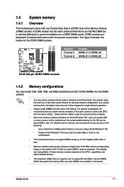
... timing or the loaded X.M.P. For effective use of memory, we recommend that you want to prevent installation on the motherboard. • This motherboard does not support DIMMs made up of the same version or date code (D/C) from the higher-sized channel is then...compatibility, we recommend that you install 4GB or more on a DDR2 DIMM socket. ASUS CS-B 1-7 The stability and compatibility of the following: - 1.4 System memory 1.4.1 Overview This motherboard comes with 8GB or above DIMMs. ASUS will update the memory QVL once the DIMMs are available in Channel A and Channel...
... timing or the loaded X.M.P. For effective use of memory, we recommend that you want to prevent installation on the motherboard. • This motherboard does not support DIMMs made up of the same version or date code (D/C) from the higher-sized channel is then...compatibility, we recommend that you install 4GB or more on a DDR2 DIMM socket. ASUS CS-B 1-7 The stability and compatibility of the following: - 1.4 System memory 1.4.1 Overview This motherboard comes with 8GB or above DIMMs. ASUS will update the memory QVL once the DIMMs are available in Channel A and Channel...
CS-B User's Manual
Page 16
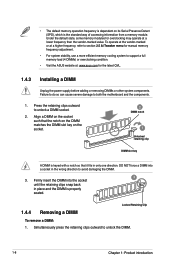
...the standard way of accessing information from a memory module. Under the default state, some memory modules for overclocking may operate at : www.asus.com for manual memory frequency adjustment. • For system stability, use a more efficient memory cooling system to avoid damaging the DIMM.... to support a full memory load (4 DIMMs) or overclocking condition. • Visit the ASUS website at a lower frequency than the vendor-marked value. Press the retaining clips outward to both the motherboard and the components. 1. Locked Retaining Clip 1.4.4 Removing a DIMM To remove a DIMM: ...
...the standard way of accessing information from a memory module. Under the default state, some memory modules for overclocking may operate at : www.asus.com for manual memory frequency adjustment. • For system stability, use a more efficient memory cooling system to avoid damaging the DIMM.... to support a full memory load (4 DIMMs) or overclocking condition. • Visit the ASUS website at a lower frequency than the vendor-marked value. Press the retaining clips outward to both the motherboard and the components. 1. Locked Retaining Clip 1.4.4 Removing a DIMM To remove a DIMM: ...

CS-B User's Manual
Page 17
... inoperable. Remove the DIMM from the socket. Before installing the expansion card, read the documentation that you physical injury and damage motherboard components. 1.5.1 Installing an expansion card To install an expansion card: 1. Replace the system cover. 1.5.2 Configuring an expansion card After...When using PCI cards on shared slots, ensure that the drivers support "Share IRQ" or that they support. ASUS CS-B 1-9 Support the DIMM lightly with your motherboard is completely seated on the slot. 5. Install the software drivers for the card. 2. Align the card connector...
... inoperable. Remove the DIMM from the socket. Before installing the expansion card, read the documentation that you physical injury and damage motherboard components. 1.5.1 Installing an expansion card To install an expansion card: 1. Replace the system cover. 1.5.2 Configuring an expansion card After...When using PCI cards on shared slots, ensure that the drivers support "Share IRQ" or that they support. ASUS CS-B 1-9 Support the DIMM lightly with your motherboard is completely seated on the slot. 5. Install the software drivers for the card. 2. Align the card connector...
CS-B User's Manual
Page 18
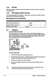
... PCI slot supports LAN cards, SCSI cards, USB cards, and other cards that comply with PCI specifications. 1.5.4 PCI Express 3.0/2.0 x16 slots This motherboard supports PCI Express x1 network cards, SCSI cards, and other cards that comply with the PCI Express specifications. shared - - - - Intel PCH...- - Removing the cap will cause system boot failure! 1-10 Chapter 1: Product introduction shared - - - - - 1.6 Jumpers 1. CLRTC 12 23 CS-B CS-B Clear RTC RAM Normal (Default) Clear RTC To erase the RTC RAM: 1. IRQ assignments for about 5-10 seconds, then move the cap back to...
... PCI slot supports LAN cards, SCSI cards, USB cards, and other cards that comply with PCI specifications. 1.5.4 PCI Express 3.0/2.0 x16 slots This motherboard supports PCI Express x1 network cards, SCSI cards, and other cards that comply with the PCI Express specifications. shared - - - - Intel PCH...- - Removing the cap will cause system boot failure! 1-10 Chapter 1: Product introduction shared - - - - - 1.6 Jumpers 1. CLRTC 12 23 CS-B CS-B Clear RTC RAM Normal (Default) Clear RTC To erase the RTC RAM: 1. IRQ assignments for about 5-10 seconds, then move the cap back to...

CS-B User's Manual
Page 23
... one end of the motherboard's high-definition audio capability. • If you intend to this connector. The signal is for details. 5. If you want to connect a high-definition front panel audio module to this connector, set to this connector. CHASSIS +5VSB_MB Chassis Signal GND CS-B PIN 1 CS-B Chassis intrusion connector ASUS CS-B 1-15 AGND NC...
... one end of the motherboard's high-definition audio capability. • If you intend to this connector. The signal is for details. 5. If you want to connect a high-definition front panel audio module to this connector, set to this connector. CHASSIS +5VSB_MB Chassis Signal GND CS-B PIN 1 CS-B Chassis intrusion connector ASUS CS-B 1-15 AGND NC...

CS-B User's Manual
Page 24
...motherboard components. SATA6G_4 GND RSATA_TXP4 RSATA_TXN4 GND RSATA_RXN4 RSATA_RXP4 GND SATA6G_3 SATA6G_5 GND RSATA_TXP5 RSATA_TXN5 GND RSATA_RXN5 RSATA_RXP5 GND GND RSATA_TXP3 RSATA_TXN3 GND RSATA_RXN3 RSATA_RXP3 GND SATA6G_1 SATA6G_2 GND RSATA_RXP2 RSATA_RXN2 GND RSATA_TXN2 RSATA_TXP2 GND GND RSATA_RXP1 RSATA_RXN1 GND RSATA_TXN1 RSATA_TXP1 GND CS-B CS... FAN IN +5V Do not forget to connect the fan cables to [AHCI]. Only the 4-pin CPU fan supports the ASUS Fan Xpert 2 feature. 7. Intel® Q87 Serial ATA 6.0Gb/s connector (7-pin SATA6G_1~5 [brown]) This connector connects ...
...motherboard components. SATA6G_4 GND RSATA_TXP4 RSATA_TXN4 GND RSATA_RXN4 RSATA_RXP4 GND SATA6G_3 SATA6G_5 GND RSATA_TXP5 RSATA_TXN5 GND RSATA_RXN5 RSATA_RXP5 GND GND RSATA_TXP3 RSATA_TXN3 GND RSATA_RXN3 RSATA_RXP3 GND SATA6G_1 SATA6G_2 GND RSATA_RXP2 RSATA_RXN2 GND RSATA_TXN2 RSATA_TXP2 GND GND RSATA_RXP1 RSATA_RXN1 GND RSATA_TXN1 RSATA_TXP1 GND CS-B CS... FAN IN +5V Do not forget to connect the fan cables to [AHCI]. Only the 4-pin CPU fan supports the ASUS Fan Xpert 2 feature. 7. Intel® Q87 Serial ATA 6.0Gb/s connector (7-pin SATA6G_1~5 [brown]) This connector connects ...

CS-B User's Manual
Page 25
...motherboard! Connect the USB module cable to any of these connectors, then install the module to a slot opening at the back of up to 5.0Gb/s, faster charging time for USB-chargeable devices, optimized power efficiency, and backward compatibility with USB 2.0. With an installed USB 3.0 module, you to the USB connectors. ASUS CS...-B 1-17 The USB 2.0 module is purchased separately. 9. USB910 USB1112 USB+5V USB_P9USB_P9+ GND NC USB+5V USB_P11USB_P11+ GND NC USB+5V USB_P10USB_P10+ GND USB+5V USB_P12USB_P12+ GND PIN 1 PIN 1 CS-B CS-B USB2.0 ...
...motherboard! Connect the USB module cable to any of these connectors, then install the module to a slot opening at the back of up to 5.0Gb/s, faster charging time for USB-chargeable devices, optimized power efficiency, and backward compatibility with USB 2.0. With an installed USB 3.0 module, you to the USB connectors. ASUS CS...-B 1-17 The USB 2.0 module is purchased separately. 9. USB910 USB1112 USB+5V USB_P9USB_P9+ GND NC USB+5V USB_P11USB_P11+ GND NC USB+5V USB_P10USB_P10+ GND USB+5V USB_P12USB_P12+ GND PIN 1 PIN 1 CS-B CS-B USB2.0 ...

CS-B User's Manual
Page 27
The illustration below shows the location of the onboard LED. SB_PWR CS-B CS-B Onboard LED ON OFF Standby Power Powered Off ASUS CS-B 1-19 Standby Power LED The motherboard comes with a standby power LED that lights up to indicate that you should shut down the system and unplug the power cable before removing or plugging in soft-off mode. This is a reminder that the system is ON, in sleep mode, or in any motherboard component. 1.8 Onboard LEDs 1.
The illustration below shows the location of the onboard LED. SB_PWR CS-B CS-B Onboard LED ON OFF Standby Power Powered Off ASUS CS-B 1-19 Standby Power LED The motherboard comes with a standby power LED that lights up to indicate that you should shut down the system and unplug the power cable before removing or plugging in soft-off mode. This is a reminder that the system is ON, in sleep mode, or in any motherboard component. 1.8 Onboard LEDs 1.

CS-B User's Manual
Page 28
... item to avail all motherboard features. Always install the latest OS version and corresponding updates to maximize the features of the Support DVD are subject to run the Support DVD Place the Support DVD into the optical drive. Visit the ASUS website at any time ...without notice. Double-click the ASSETUP.EXE to change at www.asus.com for reference only. Refer to display their respective menus. 1.9 Software support 1.9.1 Installing an operating system This motherboard supports Windows® 7 (32/64bit) and Windows® 8 (32/64bit) Operating Systems (OS). ...
... item to avail all motherboard features. Always install the latest OS version and corresponding updates to maximize the features of the Support DVD are subject to run the Support DVD Place the Support DVD into the optical drive. Visit the ASUS website at any time ...without notice. Double-click the ASSETUP.EXE to change at www.asus.com for reference only. Refer to display their respective menus. 1.9 Software support 1.9.1 Installing an operating system This motherboard supports Windows® 7 (32/64bit) and Windows® 8 (32/64bit) Operating Systems (OS). ...

CS-B User's Manual
Page 31
...that allows you to update the BIOS EZ Update requires an Internet connection either through a network or an ISP (Internet Service Provider). ASUS CS-B 2-1 Click to automatically update your motherboard's driver, software and firmware Model Name: Q87M-E Click to find and select the BIOS from file Click to select a boot ...logo Click to automatically update your BIOS 2 Save a copy of the original motherboard BIOS file to a USB flash disk in case you can also manually update the saved BIOS and select a boot logo when the system goes...
...that allows you to update the BIOS EZ Update requires an Internet connection either through a network or an ISP (Internet Service Provider). ASUS CS-B 2-1 Click to automatically update your motherboard's driver, software and firmware Model Name: Q87M-E Click to find and select the BIOS from file Click to select a boot ...logo Click to automatically update your BIOS 2 Save a copy of the original motherboard BIOS file to a USB flash disk in case you can also manually update the saved BIOS and select a boot logo when the system goes...

CS-B User's Manual
Page 33
... allows you to enter BIOS Setup to load default BIOS values. DO NOT shut down or reset the system while updating the BIOS! Prepare the motherboard support DVD and a USB flash drive formatted using this utility, rename the BIOS file in the removable device into CSB.CAP. • The BIOS... checks the devices for reference only. Turn off the computer and disconnect all SATA hard disk drives (optional). Turn on the USB flash drive. ASUS CS-B 2-3 Insert the support DVD to the optical drive or the USB flash drive that you to restore the BIOS file when it fails or gets...
... allows you to enter BIOS Setup to load default BIOS values. DO NOT shut down or reset the system while updating the BIOS! Prepare the motherboard support DVD and a USB flash drive formatted using this utility, rename the BIOS file in the removable device into CSB.CAP. • The BIOS... checks the devices for reference only. Turn off the computer and disconnect all SATA hard disk drives (optional). Turn on the USB flash drive. ASUS CS-B 2-3 Insert the support DVD to the optical drive or the USB flash drive that you to restore the BIOS file when it fails or gets...


