User Manual
Page 9
ASUS BA5120/AS-D672 PC system with • ASUS motherboard • Power supply unit • ASUS chassis 2. System package contents Check your BA5120/AS-D672 system package for the following items. If any of the items is damaged or missing, contact your retailer immediately. 1. CD • Support CD • Recovery CD 4. Documents • User guide • Warranty card ix Cable • AC power cable 3.
ASUS BA5120/AS-D672 PC system with • ASUS motherboard • Power supply unit • ASUS chassis 2. System package contents Check your BA5120/AS-D672 system package for the following items. If any of the items is damaged or missing, contact your retailer immediately. 1. CD • Support CD • Recovery CD 4. Documents • User guide • Warranty card ix Cable • AC power cable 3.
User Manual
Page 12
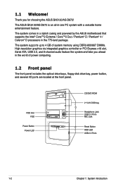
... panel. The system comes in a stylish casing and powered by the ASUS motherboard that supports the Intel® Core™2 Extreme / Core™2 Duo / Pentium® D / Pentium® 4 / Celeron® D processors in -one PC system with a versatile home entertainment feature. The ASUS BA5120/AS-D672 is an all-in the 775-land package. 1.1 Welcome...
... panel. The system comes in a stylish casing and powered by the ASUS motherboard that supports the Intel® Core™2 Extreme / Core™2 Duo / Pentium® D / Pentium® 4 / Celeron® D processors in -one PC system with a versatile home entertainment feature. The ASUS BA5120/AS-D672 is an all-in the 775-land package. 1.1 Welcome...
User Manual
Page 17
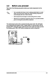
P5KPL-E SB_PWR ON Standby Power P5KPL-E/BP Onboard LED OFF Powered Off ASUS BA5120/AS-D672 2-3 The motherboard comes with the component. This LED lights up to indicate that the system is ON, in sleep mode or in the bag that the standby ...
P5KPL-E SB_PWR ON Standby Power P5KPL-E/BP Onboard LED OFF Powered Off ASUS BA5120/AS-D672 2-3 The motherboard comes with the component. This LED lights up to indicate that the system is ON, in sleep mode or in the bag that the standby ...
User Manual
Page 18
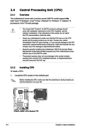
ASUS will process Return Merchandise Authorization (RMA) requests only if the motherboard comes with installation instructions for the CPU, heatsink, and the retention mechanism. 2.4 Central Processing Unit (CPU) 2.4.1 Overview The motherboard comes with a surface mount LGA775 socket supports t�h��e� ... in this section do not match the CPU documentation, follow the latter. • Check your motherboard to make sure that the PnP cap is on the motherboard. ASUS will shoulder the cost of the PnP cap. 2.4.2 Installing CPU To install a CPU: 1. If...
ASUS will process Return Merchandise Authorization (RMA) requests only if the motherboard comes with installation instructions for the CPU, heatsink, and the retention mechanism. 2.4 Central Processing Unit (CPU) 2.4.1 Overview The motherboard comes with a surface mount LGA775 socket supports t�h��e� ... in this section do not match the CPU documentation, follow the latter. • Check your motherboard to make sure that the PnP cap is on the motherboard. ASUS will shoulder the cost of the PnP cap. 2.4.2 Installing CPU To install a CPU: 1. If...
User Manual
Page 21
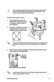
...heatsink and fan assembly may differ, but the installation steps and fucntions should remain the same. When the fan and heatsink assembly is in place. ASUS BA5120/AS-D672 2-7 CPU_FAN CPU FAN PWM CPU FAN IN CPU FAN PWR GND P5KPL-E P5KPL-E/BP CPU Fan Connector DO NOT forget to plug ... installed CPU, making sure that the Thermal Interface Material is for reference only. 3. The illustration above is properly applied to the connector on the motherboard. 2. If you purchased a separate CPU heatsink and fan assembly, ensure that the B four fasteners match the holes on the...
...heatsink and fan assembly may differ, but the installation steps and fucntions should remain the same. When the fan and heatsink assembly is in place. ASUS BA5120/AS-D672 2-7 CPU_FAN CPU FAN PWM CPU FAN IN CPU FAN PWR GND P5KPL-E P5KPL-E/BP CPU Fan Connector DO NOT forget to plug ... installed CPU, making sure that the Thermal Interface Material is for reference only. 3. The illustration above is properly applied to the connector on the motherboard. 2. If you purchased a separate CPU heatsink and fan assembly, ensure that the B four fasteners match the holes on the...

User Manual
Page 22
... following figure illustrates the location of 128 Mb chips. 2-8 Chapter 2: Basic installation Refer to the DDR2 Qualified Vendors List for the ODT value. • This motherboard does not support memory modules made up of the sockets: P5KPL-E P5KPL-E/BP 240-pin DDR2 DIMM Sockets 2.5.1 Memory configurations You may downgrade to 4 GB...-Die-Temination (0DT) requirement and may install up to run at DDR2-533. DIMM_A1 DIMM_A2 DIMM_B1 DIMM_B2 112 Pins 128 Pins 2.5 Installing a DIMM The system motherboard comes with the same CAS latency.
... following figure illustrates the location of 128 Mb chips. 2-8 Chapter 2: Basic installation Refer to the DDR2 Qualified Vendors List for the ODT value. • This motherboard does not support memory modules made up of the sockets: P5KPL-E P5KPL-E/BP 240-pin DDR2 DIMM Sockets 2.5.1 Memory configurations You may downgrade to 4 GB...-Die-Temination (0DT) requirement and may install up to run at DDR2-533. DIMM_A1 DIMM_A2 DIMM_B1 DIMM_B2 112 Pins 128 Pins 2.5 Installing a DIMM The system motherboard comes with the same CAS latency.
User Manual
Page 23
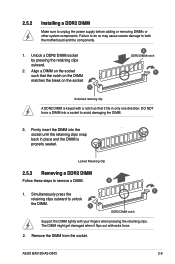
... the notch on the DIMM matches the break on the socket such that it fits in place and the DIMM is keyed with extra force. 2. ASUS BA5120/AS-D672 2-9 Failure to do so may cause severe damage to unplug the power supply before adding or removing DIMMs or other system components. Align... into a socket to avoid damaging the DIMM. 3. Unlock a DDR2 DIMM socket by pressing the retaining clips outward. 2. 2.5.2 Installing a DDR2 DIMM Make sure to both the motherboard and the components. 1.
... the notch on the DIMM matches the break on the socket such that it fits in place and the DIMM is keyed with extra force. 2. ASUS BA5120/AS-D672 2-9 Failure to do so may cause severe damage to unplug the power supply before adding or removing DIMMs or other system components. Align... into a socket to avoid damaging the DIMM. 3. Unlock a DDR2 DIMM socket by pressing the retaining clips outward. 2. 2.5.2 Installing a DDR2 DIMM Make sure to both the motherboard and the components. 1.
User Manual
Page 24
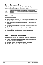
... the power cord before adding or removing expansion cards. 2.6 Expansion slots In the future, you may cause you physical injury and damage motherboard components. 2.6.1 Installing an expansion card To install an expansion card: 1. Replace the system cover. 2.6.2 Configuring an expansion card After installing... on BIOS setup. 2. Remove the bracket opposite the slot that you removed earlier. 6. Remove the system unit cover (if your motherboard is completely seated on the system and change the necessary BIOS settings, if any. Keep the screw for the expansion card. 2-10...
... the power cord before adding or removing expansion cards. 2.6 Expansion slots In the future, you may cause you physical injury and damage motherboard components. 2.6.1 Installing an expansion card To install an expansion card: 1. Replace the system cover. 2.6.2 Configuring an expansion card After installing... on BIOS setup. 2. Remove the bracket opposite the slot that you removed earlier. 6. Remove the system unit cover (if your motherboard is completely seated on the system and change the necessary BIOS settings, if any. Keep the screw for the expansion card. 2-10...
User Manual
Page 25
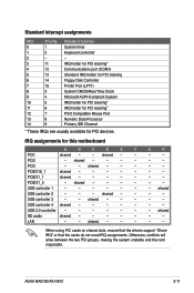
...Share IRQ" or that the cards do not need IRQ assignments. shared - - - - PCI3 - - USB 2.0 controller - - - - - - - shared - - - - - - ASUS BA5120/AS-D672 2-11 LAN - - Standard interrupt assignments IRQ Priority Standard function 0 1 System timer 1 2 Keyboard controller 2 - - 3 11 IRQ holder for PCI steering* 4 12 Communications port (COM1... Mouse Port 13 8 Numeric Data Processor 14 9 Primary IDE Channel * These IRQs are usually available for this motherboard A B C D E F G H PCI1 shared - - shared - - - -
...Share IRQ" or that the cards do not need IRQ assignments. shared - - - - PCI3 - - USB 2.0 controller - - - - - - - shared - - - - - - ASUS BA5120/AS-D672 2-11 LAN - - Standard interrupt assignments IRQ Priority Standard function 0 1 System timer 1 2 Keyboard controller 2 - - 3 11 IRQ holder for PCI steering* 4 12 Communications port (COM1... Mouse Port 13 8 Numeric Data Processor 14 9 Primary IDE Channel * These IRQs are usually available for this motherboard A B C D E F G H PCI1 shared - - shared - - - -
User Manual
Page 26
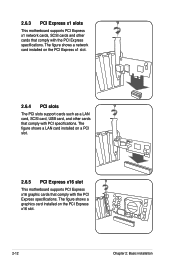
2.6.3 PCI Express x1 slots This motherboard supports PCI Express x1 network cards, SCSI cards and other cards that comply with the PCI Express specifications. The figure shows a LAN card installed on ...the PCI Express x16 slot. 2-12 Chapter 2: Basic installation The figure shows a graphics card installed on a PCI slot. 2.6.5 PCI Express x16 slot This motherboard supports PCI Express x16 graphic cards that comply with PCI specifications. The figure shows a network card installed on the PCI Express x1 slot. 2.6.4 PCI slots...
2.6.3 PCI Express x1 slots This motherboard supports PCI Express x1 network cards, SCSI cards and other cards that comply with the PCI Express specifications. The figure shows a LAN card installed on ...the PCI Express x16 slot. 2-12 Chapter 2: Basic installation The figure shows a graphics card installed on a PCI slot. 2.6.5 PCI Express x16 slot This motherboard supports PCI Express x16 graphic cards that comply with PCI specifications. The figure shows a network card installed on the PCI Express x1 slot. 2.6.4 PCI slots...
User Manual
Page 29
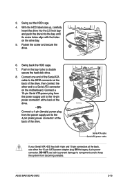
... plug OR the legacy 4‑pin power connector. ASUS BA5120/AS-D672 2-15 With the HDD label side up, carefully insert the drive into the 3.5-inch bay and push the drive into the bay until its screw holes align with the holes 5 on the motherboard. Connect a 15-pin Serial ATA power plug from...
... plug OR the legacy 4‑pin power connector. ASUS BA5120/AS-D672 2-15 With the HDD label side up, carefully insert the drive into the 3.5-inch bay and push the drive into the bay until its screw holes align with the holes 5 on the motherboard. Connect a 15-pin Serial ATA power plug from...
User Manual
Page 30
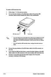
... the power connector at the back of the previous section. 2. Connect a 4-pin power plug from the power supply unit to the IDE connector on the motherboard. IDE ribbon cable Power cable • If you will install two IDE hard disk drives, configure the other device as Master device before connecting the...
... the power connector at the back of the previous section. 2. Connect a 4-pin power plug from the power supply unit to the IDE connector on the motherboard. IDE ribbon cable Power cable • If you will install two IDE hard disk drives, configure the other device as Master device before connecting the...
User Manual
Page 31
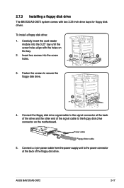
... disk drive. 3 4. ASUS BA5120/AS-D672 2-17 Fasten the screws to the signal connector at the back of the signal cable to the floppy disk drive connector on the bay. 2. Power cable Floppy ribbon cable 5. 2.7.3 Installing a floppy disk drive The BA5120/AS-D672 system comes with the holes on the motherboard. To install a floppy...
... disk drive. 3 4. ASUS BA5120/AS-D672 2-17 Fasten the screws to the signal connector at the back of the signal cable to the floppy disk drive connector on the bay. 2. Power cable Floppy ribbon cable 5. 2.7.3 Installing a floppy disk drive The BA5120/AS-D672 system comes with the holes on the motherboard. To install a floppy...
User Manual
Page 32
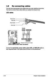
... Panel Connector Connect the reset button, power switch, power LED, and HDD LED cables to their respective leads in the system panel connector on the motherboard. 2-18 Chapter 2: Basic installation 2.8 Re-connecting cables You may have disconnected some cables when you replace the chassis cover.
... Panel Connector Connect the reset button, power switch, power LED, and HDD LED cables to their respective leads in the system panel connector on the motherboard. 2-18 Chapter 2: Basic installation 2.8 Re-connecting cables You may have disconnected some cables when you replace the chassis cover.
User Manual
Page 34
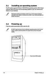
... setup procedures presented in the support CD to your hardware. DO NOT install the drivers from the Windows operating system at the first time bootup. Motherboard settings and hardware options vary. 3.1 Installing an operating system The PC system supports Windows® 2000/XP/Vista operating systems (OS). Always install the latest...
... setup procedures presented in the support CD to your hardware. DO NOT install the drivers from the Windows operating system at the first time bootup. Motherboard settings and hardware options vary. 3.1 Installing an operating system The PC system supports Windows® 2000/XP/Vista operating systems (OS). Always install the latest...
User Manual
Page 35
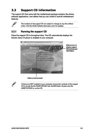
...ASUS BA5120/AS-D672 3-3 Double-click the ASSETUP.EXE to avail all motherboard features. The CD automatically displays the Drivers menu if Autorun is NOT enabled in your computer, browse the contents of the support CD are subject to the optical drive. 3.3 Support CD information The support CD that came with the motherboard... enabled in your computer. Visit the ASUS website (www.asus.com) for updates. 3.3.1 Running the support CD Place the support CD to change at any time without notice. Click an icon to display support CD/motherboard information Click an item to locate the...
...ASUS BA5120/AS-D672 3-3 Double-click the ASSETUP.EXE to avail all motherboard features. The CD automatically displays the Drivers menu if Autorun is NOT enabled in your computer, browse the contents of the support CD are subject to the optical drive. 3.3 Support CD information The support CD that came with the motherboard... enabled in your computer. Visit the ASUS website (www.asus.com) for updates. 3.3.1 Running the support CD Place the support CD to change at any time without notice. Click an icon to display support CD/motherboard information Click an item to locate the...
User Manual
Page 37
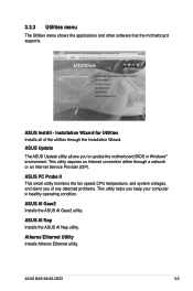
... computer in Windows® environment. Installation Wizard for Utilities Installs all of any detected problems. This utility helps you to update the motherboard BIOS in healthy operating condition. ASUS BA5120/AS-D672 3-5 ASUS InstAll - ASUS AI Nap Installs the ASUS AI Nap utility. 3.3.3 Utilities menu The Utilities menu shows the applications and other software that the...
... computer in Windows® environment. Installation Wizard for Utilities Installs all of any detected problems. This utility helps you to update the motherboard BIOS in healthy operating condition. ASUS BA5120/AS-D672 3-5 ASUS InstAll - ASUS AI Nap Installs the ASUS AI Nap utility. 3.3.3 Utilities menu The Utilities menu shows the applications and other software that the...
User Manual
Page 39
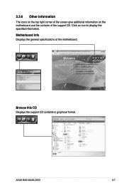
Browse this CD Displays the support CD contents in graphical format. ASUS BA5120/AS-D672 3-7 Motherboard Info Displays the general specifications of the support CD. Click an icon to display the specified information. 3.3.6 Other information The icons on the top right corner of the screen give additional information on the motherboard and the contents of the motherboard.
Browse this CD Displays the support CD contents in graphical format. ASUS BA5120/AS-D672 3-7 Motherboard Info Displays the general specifications of the support CD. Click an icon to display the specified information. 3.3.6 Other information The icons on the top right corner of the screen give additional information on the motherboard and the contents of the motherboard.


