User Manual
Page 2
SPECIFICATIONS AND INFORMATION CONTAINED IN THIS MANUAL ARE FURNISHED FOR INFORMATIONAL USE ONLY, AND ARE SUBJECT TO CHANGE AT ANY TIME WITHOUT NOTICE, AND SHOULD NOT BE CONSTRUED AS A COMMITMENT BY ASUS. or (2) the serial number of ASUSTeK COMPUTER INC. ("ASUS"). E3597 First Edition V1 December 2007 Copyright © 2007 ASUSTeK COMPUTER INC. All Rights Reserved. ASUS PROVIDES THIS MANUAL "AS...
SPECIFICATIONS AND INFORMATION CONTAINED IN THIS MANUAL ARE FURNISHED FOR INFORMATIONAL USE ONLY, AND ARE SUBJECT TO CHANGE AT ANY TIME WITHOUT NOTICE, AND SHOULD NOT BE CONSTRUED AS A COMMITMENT BY ASUS. or (2) the serial number of ASUSTeK COMPUTER INC. ("ASUS"). E3597 First Edition V1 December 2007 Copyright © 2007 ASUSTeK COMPUTER INC. All Rights Reserved. ASUS PROVIDES THIS MANUAL "AS...
User Manual
Page 3
... Installing CPU 2-4 2.4.3 Installing the CPU fan and heatsink assembly 2-6 2.5 Installing a DIMM 2-8 2.5.1 Memory configurations 2-8 2.5.2 Installing a DDR2 DIMM 2-9 2.5.3 Removing a DDR2 DIMM 2-9 2.6 Expansion slots 2-10 2.6.1 Installing an expansion card 2-10 2.6.2 Configuring an expansion card 2-10 2.6.3 PCI Express x1 slots 2-12 2.6.4 PCI slots 2-12 2.6.5 PCI Express x16 slot 2-12 2.7 Installing disk drives 2-13 2.7.1 Installing an optical drive 2-13 2.7.2 Installing a hard disk drive 2-14 2.7.3 Installing a floppy disk drive 2-17 2.8 Re-connecting cables 2-18 LED cables...
... Installing CPU 2-4 2.4.3 Installing the CPU fan and heatsink assembly 2-6 2.5 Installing a DIMM 2-8 2.5.1 Memory configurations 2-8 2.5.2 Installing a DDR2 DIMM 2-9 2.5.3 Removing a DDR2 DIMM 2-9 2.6 Expansion slots 2-10 2.6.1 Installing an expansion card 2-10 2.6.2 Configuring an expansion card 2-10 2.6.3 PCI Express x1 slots 2-12 2.6.4 PCI slots 2-12 2.6.5 PCI Express x16 slot 2-12 2.7 Installing disk drives 2-13 2.7.1 Installing an optical drive 2-13 2.7.2 Installing a hard disk drive 2-14 2.7.3 Installing a floppy disk drive 2-17 2.8 Re-connecting cables 2-18 LED cables...
User Manual
Page 5
...device complies with Canadian ICES-003. This equipment has been tested and found to which can radiate radio frequency energy and, if not installed and used in municipal waste. The use of shielded cables for radio noise emissions from that may cause harmful interference to the graphics card...for connection of the crossed out wheeled bin indicates that the product (electrical, electronic equipment, and mercury-containing button cell battery) should not be determined by turning the equipment off and on a circuit different from digital apparatus set out in a residential installation....
...device complies with Canadian ICES-003. This equipment has been tested and found to which can radiate radio frequency energy and, if not installed and used in municipal waste. The use of shielded cables for radio noise emissions from that may cause harmful interference to the graphics card...for connection of the crossed out wheeled bin indicates that the product (electrical, electronic equipment, and mercury-containing button cell battery) should not be determined by turning the equipment off and on a circuit different from digital apparatus set out in a residential installation....
User Manual
Page 6
... der Batterie. Operation safety • Before installing devices into the system, carefully read all cables are correctly connected and the power cables are connected. • If the power supply is incorrectly replaced. Lithium-Ion Battery Warning CAUTION: Danger of used batteries according to fix it may become wet. Do not place the product in any damage, contact your retailer. Replace only with the product, contact a qualified service...
... der Batterie. Operation safety • Before installing devices into the system, carefully read all cables are correctly connected and the power cables are connected. • If the power supply is incorrectly replaced. Lithium-Ion Battery Warning CAUTION: Danger of used batteries according to fix it may become wet. Do not place the product in any damage, contact your retailer. Replace only with the product, contact a qualified service...
User Manual
Page 12
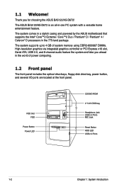
... I/O ports are located at the front panel. FDD Slot FDD Power Button Power LED CD/DVD ROM 2* 5.25 ODD bay Headphone Jack USB 2.0 Ports MIC Jack Reset Button HDD LED USB 2.0 Ports 1-2 Chapter 1: System introduction 1.1 Welcome! Thank you ahead in the world of system memory using DDR2-800/667 DIMMs. High-resolution graphics via integrated graphics controller or PCI Express x16 slot, Serial ATA, USB 2.0, and 8-channel audio feature the system and take you for choosing the ASUS BA5120/AS...
... I/O ports are located at the front panel. FDD Slot FDD Power Button Power LED CD/DVD ROM 2* 5.25 ODD bay Headphone Jack USB 2.0 Ports MIC Jack Reset Button HDD LED USB 2.0 Ports 1-2 Chapter 1: System introduction 1.1 Welcome! Thank you ahead in the world of system memory using DDR2-800/667 DIMMs. High-resolution graphics via integrated graphics controller or PCI Express x16 slot, Serial ATA, USB 2.0, and 8-channel audio feature the system and take you for choosing the ASUS BA5120/AS...

User Manual
Page 13
... REAR S P K SIDE S P K LINE IN CTR BASS Power Supply Switch Parallel Port Chassis Fan Vent LAN (RJ-45) Port Expansion Slot Cover Side Cover Lock (One at each side) Voltage selector The PSU has a 115V/230V voltage selector switch located beside the power connector. If the voltage supply in a 115V environment will seriously damage the system! ASUS BA5120/AS-D672 1-3 Voltage selector Power Connector PS/2 Mouse Port PS/2 Keyboard Port COM1 Port VGA Port USB 2.0 Ports Audio I /O ports that allow convenient connection of devices...
... REAR S P K SIDE S P K LINE IN CTR BASS Power Supply Switch Parallel Port Chassis Fan Vent LAN (RJ-45) Port Expansion Slot Cover Side Cover Lock (One at each side) Voltage selector The PSU has a 115V/230V voltage selector switch located beside the power connector. If the voltage supply in a 115V environment will seriously damage the system! ASUS BA5120/AS-D672 1-3 Voltage selector Power Connector PS/2 Mouse Port PS/2 Keyboard Port COM1 Port VGA Port USB 2.0 Ports Audio I /O ports that allow convenient connection of devices...
User Manual
Page 16
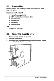
... card(s) 4. Optical drive 6. Unlock the side cover lock. 3. Pull the side cover toward the rear panel until its hooks disengage from the chassis tab holes. Basic components to install in the system. DDR2 Dual Inline Memory Module(s) (DIMM) 3. 2.1 Preparation Before you proceed, make sure that you have all the components you plan to install 1. Hard disk drive 5. Central Processing Unit (CPU) 2. Remove the cover screws on the rear panel. 2. Floppy disk drive...
... card(s) 4. Optical drive 6. Unlock the side cover lock. 3. Pull the side cover toward the rear panel until its hooks disengage from the chassis tab holes. Basic components to install in the system. DDR2 Dual Inline Memory Module(s) (DIMM) 3. 2.1 Preparation Before you proceed, make sure that you have all the components you plan to install 1. Hard disk drive 5. Central Processing Unit (CPU) 2. Remove the cover screws on the rear panel. 2. Floppy disk drive...
User Manual
Page 17
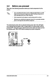
... them. • Whenever you install components into the system. • Use a grounded wrist strap or touch a safely grounded object or a metal object, such as the power supply case, before installing any component, place it on a grounded antistatic pad or in soft-off mode, and not powered OFF. P5KPL-E SB_PWR ON Standby Power P5KPL-E/BP Onboard LED OFF Powered Off ASUS BA5120/AS-D672 2-3
... them. • Whenever you install components into the system. • Use a grounded wrist strap or touch a safely grounded object or a metal object, such as the power supply case, before installing any component, place it on a grounded antistatic pad or in soft-off mode, and not powered OFF. P5KPL-E SB_PWR ON Standby Power P5KPL-E/BP Onboard LED OFF Powered Off ASUS BA5120/AS-D672 2-3
User Manual
Page 21
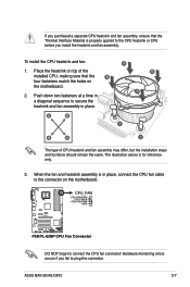
... the installed CPU, making sure that the Thermal Interface Material is properly applied to the connector on the motherboard. The illustration above is in place. When the fan and heatsink assembly is for reference only. 3. ASUS BA5120/AS-D672 2-7 CPU_FAN CPU FAN PWM CPU FAN IN CPU FAN PWR GND P5KPL-E P5KPL-E/BP CPU Fan Connector DO NOT forget to plug this connector. Hardware monitoring errors occurs if you fail to connect the CPU fan connector...
... the installed CPU, making sure that the Thermal Interface Material is properly applied to the connector on the motherboard. The illustration above is in place. When the fan and heatsink assembly is for reference only. 3. ASUS BA5120/AS-D672 2-7 CPU_FAN CPU FAN PWM CPU FAN IN CPU FAN PWR GND P5KPL-E P5KPL-E/BP CPU Fan Connector DO NOT forget to plug this connector. Hardware monitoring errors occurs if you fail to connect the CPU fan connector...
User Manual
Page 24
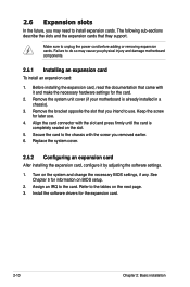
... the software settings. 1. Remove the bracket opposite the slot that they support. Secure the card to use . 4. Replace the system cover. 2.6.2 Configuring an expansion card After installing the expansion card, configure it and make the necessary hardware settings for information on the next page. 3. See Chapter 5 for the card. 2. Install the software drivers for later use . Make sure to the tables on BIOS setup. 2. Refer to unplug the power cord before adding or removing expansion cards. Failure to the card. Keep...
... the software settings. 1. Remove the bracket opposite the slot that they support. Secure the card to use . 4. Replace the system cover. 2.6.2 Configuring an expansion card After installing the expansion card, configure it and make the necessary hardware settings for information on the next page. 3. See Chapter 5 for the card. 2. Install the software drivers for later use . Make sure to the tables on BIOS setup. 2. Refer to unplug the power cord before adding or removing expansion cards. Failure to the card. Keep...
User Manual
Page 25
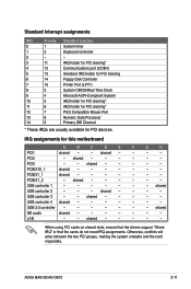
IRQ assignments for PCI devices. shared USB controller 2 - - - shared - - - - - LAN - - When using PCI cards on shared slots, ensure that the drivers support "Share IRQ" or that the cards do not need IRQ assignments. shared - - - - shared - - - - - - shared - - - - - USB controller 3 - - Otherwise, conflicts will arise between the two PCI groups, making the system unstable and the card inoperable. PCIEX1_1 shared - - - - - - - shared - - - - - - shared HD audio shared - - - - - - - PCI2 - PCIEX1_2 - USB controller 1 -...
IRQ assignments for PCI devices. shared USB controller 2 - - - shared - - - - - LAN - - When using PCI cards on shared slots, ensure that the drivers support "Share IRQ" or that the cards do not need IRQ assignments. shared - - - - shared - - - - - - shared - - - - - USB controller 3 - - Otherwise, conflicts will arise between the two PCI groups, making the system unstable and the card inoperable. PCIEX1_1 shared - - - - - - - shared - - - - - - shared HD audio shared - - - - - - - PCI2 - PCIEX1_2 - USB controller 1 -...
User Manual
Page 28
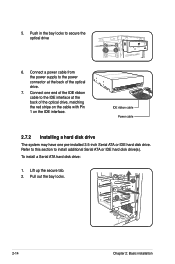
... IDE hard disk drive. To install a Serial ATA hard disk drive: 1. Lift up the secure tab. 2. Pull out the bay locks. 1 2 2-14 Chapter 2: Basic installation Connect a power cable from the power supply to install additional Serial ATA or IDE hard disk drive(s). IDE ribbon cable Power cable 2.7.2 Installing a hard disk drive The system may have one end of the optical drive, matching the red stripe on the cable with Pin 1 on the IDE interface. Refer to this section to the power connector...
... IDE hard disk drive. To install a Serial ATA hard disk drive: 1. Lift up the secure tab. 2. Pull out the bay locks. 1 2 2-14 Chapter 2: Basic installation Connect a power cable from the power supply to install additional Serial ATA or IDE hard disk drive(s). IDE ribbon cable Power cable 2.7.2 Installing a hard disk drive The system may have one end of the optical drive, matching the red stripe on the cable with Pin 1 on the IDE interface. Refer to this section to the power connector...
User Manual
Page 29
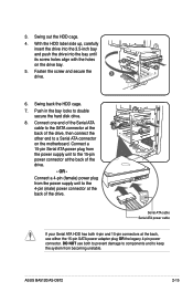
... the system from the power supply unit to double secure the hard disk drive. 8. Connect one end of the Serial ATA cable to the SATA connector at the 8 back of the drive, then connect the 7 other end to the 4-pin (male) power connector at the back of the drive. - Swing back the HDD cage. 7. DO NOT use either the 15-pin SATA power adapter plug OR the legacy 4‑pin power connector. Fasten the screw and...
... the system from the power supply unit to double secure the hard disk drive. 8. Connect one end of the Serial ATA cable to the SATA connector at the 8 back of the drive, then connect the 7 other end to the 4-pin (male) power connector at the back of the drive. - Swing back the HDD cage. 7. DO NOT use either the 15-pin SATA power adapter plug OR the legacy 4‑pin power connector. Fasten the screw and...
User Manual
Page 30
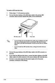
... IDE ribbon cable to the HDD documentation on the drive. 4. Connect a 4-pin power plug from the power supply unit to configure your hard disk drive as Master device before connecting the IDE cable and power plug. To install an IDE hard disk drive: 1. IDE ribbon cable Power cable • If you will install two IDE hard disk drives, configure the other device as a Master device. • If you install two IDE hard disk drives, connect the black interface of the IDE ribbon cable to the primary IDE connector (blue connector labeled...
... IDE ribbon cable to the HDD documentation on the drive. 4. Connect a 4-pin power plug from the power supply unit to configure your hard disk drive as Master device before connecting the IDE cable and power plug. To install an IDE hard disk drive: 1. IDE ribbon cable Power cable • If you will install two IDE hard disk drives, configure the other device as a Master device. • If you install two IDE hard disk drives, connect the black interface of the IDE ribbon cable to the primary IDE connector (blue connector labeled...
User Manual
Page 34
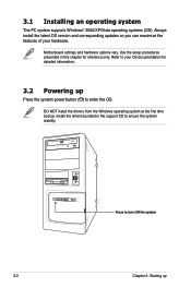
Use the setup procedures presented in the support CD to turn ON the system 3-2 Chapter 3: Starting up Press the system power button ( ) to your hardware. Always install the latest OS version and corresponding updates so you can maximize the features of your OS documentation for reference only. DO NOT install the drivers from the Windows operating system at the first time bootup. Motherboard settings and hardware options vary. Install the...
Use the setup procedures presented in the support CD to turn ON the system 3-2 Chapter 3: Starting up Press the system power button ( ) to your hardware. Always install the latest OS version and corresponding updates so you can maximize the features of your OS documentation for reference only. DO NOT install the drivers from the Windows operating system at the first time bootup. Motherboard settings and hardware options vary. Install the...
User Manual
Page 35
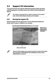
... updates. 3.3.1 Running the support CD Place the support CD to avail all motherboard features. ASUS BA5120/AS-D672 3-3 3.3 Support CD information The support CD that came with the motherboard package contains the drivers, software applications, and utilities that you can install to the optical drive. Double-click the ASSETUP.EXE to change at any time without notice. Click an icon to display support CD/motherboard information Click an item to locate...
... updates. 3.3.1 Running the support CD Place the support CD to avail all motherboard features. ASUS BA5120/AS-D672 3-3 3.3 Support CD information The support CD that came with the motherboard package contains the drivers, software applications, and utilities that you can install to the optical drive. Double-click the ASSETUP.EXE to change at any time without notice. Click an icon to display support CD/motherboard information Click an item to locate...
User Manual
Page 36
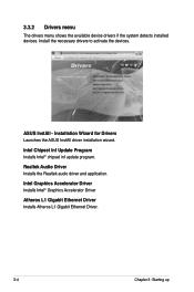
... Program Installs Intel® chipset inf update program. Install the necessary drivers to activate the devices. Realtek Audio Driver Installs the Realtek audio driver and application. 3.3.2 Drivers menu The drivers menu shows the available device drivers if the system detects installed devices. ASUS InstAll - Installation Wizard for Drivers Launches the ASUS InstAll driver installation wizard. Intel Graphics Accelerator Driver Installs Intel® Graphics Accelerator Driver Atheros L1 Gigabit Ethernet Driver Installs Atheros L1 Gigabit Ethernet Driver. 3-4 Chapter 3: Starting...
... Program Installs Intel® chipset inf update program. Install the necessary drivers to activate the devices. Realtek Audio Driver Installs the Realtek audio driver and application. 3.3.2 Drivers menu The drivers menu shows the available device drivers if the system detects installed devices. ASUS InstAll - Installation Wizard for Drivers Launches the ASUS InstAll driver installation wizard. Intel Graphics Accelerator Driver Installs Intel® Graphics Accelerator Driver Atheros L1 Gigabit Ethernet Driver Installs Atheros L1 Gigabit Ethernet Driver. 3-4 Chapter 3: Starting...
User Manual
Page 37
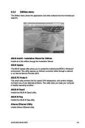
... fan speed, CPU temperature, and system voltages, and alerts you of the utilities through a network or an Internet Service Provider (ISP). ASUS AI Nap Installs the ASUS AI Nap utility. ASUS InstAll - 3.3.3 Utilities menu The Utilities menu shows the applications and other software that the motherboard supports. Installation Wizard for Utilities Installs all of any detected problems. This utility helps you to update the motherboard BIOS in healthy operating condition. ASUS BA5120/AS-D672 3-5 ASUS Update The ASUS Update utility allows you keep your computer in Windows...
... fan speed, CPU temperature, and system voltages, and alerts you of the utilities through a network or an Internet Service Provider (ISP). ASUS AI Nap Installs the ASUS AI Nap utility. ASUS InstAll - 3.3.3 Utilities menu The Utilities menu shows the applications and other software that the motherboard supports. Installation Wizard for Utilities Installs all of any detected problems. This utility helps you to update the motherboard BIOS in healthy operating condition. ASUS BA5120/AS-D672 3-5 ASUS Update The ASUS Update utility allows you keep your computer in Windows...
User Manual
Page 41
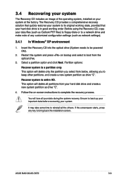
... powered ON). 2. 3.4 Recovering your system The Recovery CD includes an image of any key to bring back the installation screen. Select a partition option and click Next. Before using the Recovery CD, copy your data files (such as network settings). 3.4.1 In Windows® XP environment 1. If the screensaver starts, press any customized configuration settings (such as Outlook PST files) to floppy disks or to a network drive and make note of the operating...
... powered ON). 2. 3.4 Recovering your system The Recovery CD includes an image of any key to bring back the installation screen. Select a partition option and click Next. Before using the Recovery CD, copy your data files (such as network settings). 3.4.1 In Windows® XP environment 1. If the screensaver starts, press any customized configuration settings (such as Outlook PST files) to floppy disks or to a network drive and make note of the operating...
User Manual
Page 42
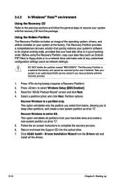
... a new system partition as drive "C". 5. The Recovery Partition provides a comprehensive recovery solution that your system's software to select Windows Setup [EMS Enabled] 3. DO NOT delete the partition named "RECOVERY." Reboot and insert the Support CD into the optical drive. 7. Click ASUS InstAll - The Recovery Partition is in good working order. Press to its original working state, provided that quickly restores your hard disk drive is created at the factory. This option will delete all the drivers. 3-10 Chapter 3: Starting up...
... a new system partition as drive "C". 5. The Recovery Partition provides a comprehensive recovery solution that your system's software to select Windows Setup [EMS Enabled] 3. DO NOT delete the partition named "RECOVERY." Reboot and insert the Support CD into the optical drive. 7. Click ASUS InstAll - The Recovery Partition is in good working order. Press to its original working state, provided that quickly restores your hard disk drive is created at the factory. This option will delete all the drivers. 3-10 Chapter 3: Starting up...


