B150 PRO GAMING/AURA Users manual English
Page 8
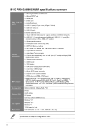
viii B150 PRO GAMING/AURA specifications summary Rear Panel I/O ports Internal connectors BIOS features ...X CPU Over Voltage jumper (CPU_OV) 1 x 2-pin Clear CMOS jumper 1 x 24-pin EATX power connector 1 x 8-pin ATX 12V power connector 1 x ROG extension (ROG_EXT) header 128 Mb Flash ROM, UEFI AMI BIOS, PnP, DMI 3.0, WfM 2.0, SM BIOS 3.0,... F9 Quick Note, Last Modified Log, F12 PrintScreen function, and ASUS DRAM SPD (Serial Presence Detect) memory information WfM 2.0, DMI 3.0, WOL by PME, PXE Drivers ASUS utilities EZ Update Anti-virus software (OEM version) Windows® 10...
viii B150 PRO GAMING/AURA specifications summary Rear Panel I/O ports Internal connectors BIOS features ...X CPU Over Voltage jumper (CPU_OV) 1 x 2-pin Clear CMOS jumper 1 x 24-pin EATX power connector 1 x 8-pin ATX 12V power connector 1 x ROG extension (ROG_EXT) header 128 Mb Flash ROM, UEFI AMI BIOS, PnP, DMI 3.0, WfM 2.0, SM BIOS 3.0,... F9 Quick Note, Last Modified Log, F12 PrintScreen function, and ASUS DRAM SPD (Serial Presence Detect) memory information WfM 2.0, DMI 3.0, WOL by PME, PXE Drivers ASUS utilities EZ Update Anti-virus software (OEM version) Windows® 10...
B150 PRO GAMING/AURA Users manual English
Page 9
... indicated by circles to secure the motherboard to ensure that the ATX power supply is switched off or the power cord is detached from the power supply. Do not overtighten the screws! Failure to do so can damage the motherboard. ASUS B150 PRO GAMING/AURA 1-1 Unplug the power cord before touching any component, ensure that the...
... indicated by circles to secure the motherboard to ensure that the ATX power supply is switched off or the power cord is detached from the power supply. Do not overtighten the screws! Failure to do so can damage the motherboard. ASUS B150 PRO GAMING/AURA 1-1 Unplug the power cord before touching any component, ensure that the...
B150 PRO GAMING/AURA Users manual English
Page 11
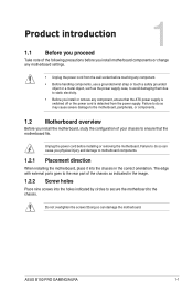
1.2.4 Layout contents Connectors/Jumpers/Slots/LED 1. Intel® LGA1151 CPU socket 4. DDR4 DIMM slots 5. Intel® B150 Serial ATA 6.0 Gb/s connector (7-pin SATA6G_1~6) 9. TPM connector (14-1 pin TPM) 18. SupremeFX LED Page 1-20 1-19 1-3 1-7 1-... (2-pin T_SENSOR) 13. CPU Over Voltage jumper (3-pin CPU_OV) 11. Q LEDs (BOOT_DEVICE_LED, VGA_LED, DRAM_LED, CPU_LED) 7. B150 PRO GAMING/AURA CPU socket LGA1151 ASUS B150 PRO GAMING/AURA 1-3 USB 2.0 connectors (10-1 pin USB910, USB1112) 16. ATX power connectors (24-pin EATXPWR, 8-pin ATX12V) 2. System panel connector (20-5 pin PANEL) 12.
1.2.4 Layout contents Connectors/Jumpers/Slots/LED 1. Intel® LGA1151 CPU socket 4. DDR4 DIMM slots 5. Intel® B150 Serial ATA 6.0 Gb/s connector (7-pin SATA6G_1~6) 9. TPM connector (14-1 pin TPM) 18. SupremeFX LED Page 1-20 1-19 1-3 1-7 1-... (2-pin T_SENSOR) 13. CPU Over Voltage jumper (3-pin CPU_OV) 11. Q LEDs (BOOT_DEVICE_LED, VGA_LED, DRAM_LED, CPU_LED) 7. B150 PRO GAMING/AURA CPU socket LGA1151 ASUS B150 PRO GAMING/AURA 1-3 USB 2.0 connectors (10-1 pin USB910, USB1112) 16. ATX power connectors (24-pin EATXPWR, 8-pin ATX12V) 2. System panel connector (20-5 pin PANEL) 12.
B150 PRO GAMING/AURA Users manual English
Page 28
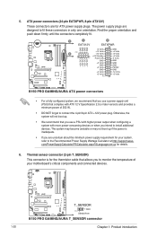
... GND +5 Volts GND +3 Volts +3 Volts PIN 1 GND +5 Volts +5 Volts +5 Volts -5 Volts GND GND GND PSON# GND -12 Volts +3 Volts B150 PRO GAMING/AURA ATX power connectors • For a fully configured system, we recommend that you use a PSU with higher power output when configuring a system with...the proper orientation and push down firmly until the connectors completely fit. ATX power connectors (24-pin EATXPWR, 8-pin ATX12V) These connectors are designed to the Recommended Power Supply Wattage Calculator at http://support.asus. The system may become unstable or may not boot up . •...
... GND +5 Volts GND +3 Volts +3 Volts PIN 1 GND +5 Volts +5 Volts +5 Volts -5 Volts GND GND GND PSON# GND -12 Volts +3 Volts B150 PRO GAMING/AURA ATX power connectors • For a fully configured system, we recommend that you use a PSU with higher power output when configuring a system with...the proper orientation and push down firmly until the connectors completely fit. ATX power connectors (24-pin EATXPWR, 8-pin ATX12V) These connectors are designed to the Recommended Power Supply Wattage Calculator at http://support.asus. The system may become unstable or may not boot up . •...

B150 PRO GAMING/AURA Users manual English
Page 32
... system power. 1-24 Chapter 1: Product introduction Pressing the power button turns the system on the operating system settings. PANEL +PWR_LED- RESET +PWR_LED* Requires an ATX power supply B150 PRO GAMING/AURA System panel connector • System power LED (4-pin +PWR_LED-) This 4-pin connector is for the chassis-mounted reset button for system reboot without turning...
... system power. 1-24 Chapter 1: Product introduction Pressing the power button turns the system on the operating system settings. PANEL +PWR_LED- RESET +PWR_LED* Requires an ATX power supply B150 PRO GAMING/AURA System panel connector • System power LED (4-pin +PWR_LED-) This 4-pin connector is for the chassis-mounted reset button for system reboot without turning...
B150 PRO GAMING/AURA Users manual English
Page 67
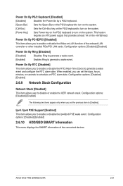
Configuration options: [Disabled] [Enabled] The following two items appear only when you to enable or disable the RTC (Real-Time Clock) to [Enabled]. ASUS B150 PRO GAMING/AURA 2-31 Power On By RTC [Disabled] This item allows you set the days, hours, minutes, or seconds to turn on the system. [Power Key] Sets ...to turn on the system. [Ctrl-Esc] Sets the Ctrl+Esc key on the PS/2 keyboard to turn on the system. This feature requires an ATX power supply that provides at least 1A on the PS/2 keyboard to schedule an RTC alarm date. When enabled, you can set the previous item...
Configuration options: [Disabled] [Enabled] The following two items appear only when you to enable or disable the RTC (Real-Time Clock) to [Enabled]. ASUS B150 PRO GAMING/AURA 2-31 Power On By RTC [Disabled] This item allows you set the days, hours, minutes, or seconds to turn on the system. [Power Key] Sets ...to turn on the system. [Ctrl-Esc] Sets the Ctrl+Esc key on the PS/2 keyboard to turn on the system. This feature requires an ATX power supply that provides at least 1A on the PS/2 keyboard to schedule an RTC alarm date. When enabled, you can set the previous item...

