User Manual
Page 2
...ERRORS OR INACCURACIES THAT MAY APPEAR IN THIS MANUAL, INCLUDING THE PRODUCTS AND SOFTWARE DESCRIBED IN IT. The GPL and LGPL licensed code in the About Box of these licenses are used only for backup purposes, without intent to : ASUSTeK Computer Inc. or (2) the serial number of the product is distributed without any problems...http://support.asus.com/download; You may obtain the complete corresponding source code (as the corresponding binary/object code. SPECIFICATIONS AND INFORMATION CONTAINED IN THIS MANUAL ARE FURNISHED FOR INFORMATIONAL USE ONLY, AND ARE SUBJECT TO CHANGE AT...
...ERRORS OR INACCURACIES THAT MAY APPEAR IN THIS MANUAL, INCLUDING THE PRODUCTS AND SOFTWARE DESCRIBED IN IT. The GPL and LGPL licensed code in the About Box of these licenses are used only for backup purposes, without intent to : ASUSTeK Computer Inc. or (2) the serial number of the product is distributed without any problems...http://support.asus.com/download; You may obtain the complete corresponding source code (as the corresponding binary/object code. SPECIFICATIONS AND INFORMATION CONTAINED IN THIS MANUAL ARE FURNISHED FOR INFORMATIONAL USE ONLY, AND ARE SUBJECT TO CHANGE AT...

User Manual
Page 3
... Unit (CPU 1-3 1.4 System memory 1-3 1.4.1 Overview 1-3 1.4.2 Memory configurations 1-4 1.5 Expansion slot 1-8 1.5.1 Installing an expansion card 1-8 1.5.2 Configuring an expansion card 1-8 1.5.3 PCI slot 1-8 1.6 Jumpers 1-9 1.7 Connectors 1-11 1.7.1 Rear panel connectors 1-11 1.7.2 Internal connectors 1-12 1.8 Software support 1-18 1.8.1 Installing an operating system 1-18 1.8.2 Support DVD information 1-18 Chapter 2: BIOS information 2.1 Managing and updating your BIOS 2-1 2.1.1 ASUS Update utility 2-1 2.1.2 ASUS EZ Flash 2 2-2 2.1.3 ASUS CrashFree BIOS 2-3 2.2 BIOS setup...
... Unit (CPU 1-3 1.4 System memory 1-3 1.4.1 Overview 1-3 1.4.2 Memory configurations 1-4 1.5 Expansion slot 1-8 1.5.1 Installing an expansion card 1-8 1.5.2 Configuring an expansion card 1-8 1.5.3 PCI slot 1-8 1.6 Jumpers 1-9 1.7 Connectors 1-11 1.7.1 Rear panel connectors 1-11 1.7.2 Internal connectors 1-12 1.8 Software support 1-18 1.8.1 Installing an operating system 1-18 1.8.2 Support DVD information 1-18 Chapter 2: BIOS information 2.1 Managing and updating your BIOS 2-1 2.1.1 ASUS Update utility 2-1 2.1.2 ASUS EZ Flash 2 2-2 2.1.3 ASUS CrashFree BIOS 2-3 2.2 BIOS setup...

User Manual
Page 6
..., and staples away from connectors, slots, sockets and circuitry. • Avoid dust, humidity, and temperature extremes. Contact a qualified service technician or your area. About this guide is set to fix it supports. • Chapter 2: BIOS information This chapter tells how to or from the system, ensure that the power cables for the devices are unplugged before the signal cables are unplugged. • Seek...
..., and staples away from connectors, slots, sockets and circuitry. • Avoid dust, humidity, and temperature extremes. Contact a qualified service technician or your area. About this guide is set to fix it supports. • Chapter 2: BIOS information This chapter tells how to or from the system, ensure that the power cables for the devices are unplugged before the signal cables are unplugged. • Seek...

User Manual
Page 8
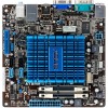
...CPU Chipset Memory Graphics Expansion slot Storage Audio LAN USB ASUS special features Rear panel ports Integrated Dual-Core Intel® Atom™ D510 processor Intel® NM10 Single channel memory architecture - 2 x 240-pin DIMM sockets support maximum 4GB unbuffered non-ECC 800/667 MHz DDR2 memory modules * Refer to 8 USB 2.0/1.1 ports (4 ports at mid-board, 4 ports at back panel) ASUS CrashFree BIOS 3 ASUS EZ Flash 2 ASUS MyLogo 2™ ASUS Express Gate 1 x PS/2 Keyboard port 1 x PS/2 Mouse port 1 x COM port 1 x VGA port 1 x LPT port 1 x LAN (RJ-45) port 4 x USB 2.0/1.1 ports...
...CPU Chipset Memory Graphics Expansion slot Storage Audio LAN USB ASUS special features Rear panel ports Integrated Dual-Core Intel® Atom™ D510 processor Intel® NM10 Single channel memory architecture - 2 x 240-pin DIMM sockets support maximum 4GB unbuffered non-ECC 800/667 MHz DDR2 memory modules * Refer to 8 USB 2.0/1.1 ports (4 ports at mid-board, 4 ports at back panel) ASUS CrashFree BIOS 3 ASUS EZ Flash 2 ASUS MyLogo 2™ ASUS Express Gate 1 x PS/2 Keyboard port 1 x PS/2 Mouse port 1 x COM port 1 x VGA port 1 x LPT port 1 x LAN (RJ-45) port 4 x USB 2.0/1.1 ports...
User Manual
Page 11
.../22/09 5:55:43 PM Internal speaker connector (4-pin SPEAKER) 1-14 3. ATX power connectors (24-pin EATXPWR, 4-pin ATX12V) 1-12 11. LVDS connector (30-pin CON1) 1-16 13. USB connector (10-1 pin USB56, USB78) 1-13 7. Place four screws into the chassis in the correct orientation. Clear RTC RAM (3-pin CLRTC) 1-9 4. DIMM socket 1-3 15. CPU and chassis fan connectors (3-pin CPU_FAN, 3-pin CHA_FAN) 1-15 12. Digital audio connector (4-1 pin SPDIF_OUT) 1-17 8. Serial ATA connectors (7-pin SATA1, SATA2) 1-13 6. Serial port connectors (10-1 pin COM2) 1-17 10. The...
.../22/09 5:55:43 PM Internal speaker connector (4-pin SPEAKER) 1-14 3. ATX power connectors (24-pin EATXPWR, 4-pin ATX12V) 1-12 11. LVDS connector (30-pin CON1) 1-16 13. USB connector (10-1 pin USB56, USB78) 1-13 7. Place four screws into the chassis in the correct orientation. Clear RTC RAM (3-pin CLRTC) 1-9 4. DIMM socket 1-3 15. CPU and chassis fan connectors (3-pin CPU_FAN, 3-pin CHA_FAN) 1-15 12. Digital audio connector (4-1 pin SPDIF_OUT) 1-17 8. Serial ATA connectors (7-pin SATA1, SATA2) 1-13 6. Serial port connectors (10-1 pin COM2) 1-17 10. The...

User Manual
Page 17
... card. 3. Replace the system cover. 1.5.2 Configuring an expansion card After installing the expansion card, configure it supports. Install the software drivers for later use . ASUS AT5NM10-I E5179_AT5NM10-I.indb 8 1-8 12/22/09 5:55:53 PM Keep the screw for the expansion card. 1.5.3 PCI slot The PCI slot supports cards such as a LAN card, SCSI card, USB card, and other cards that it by adjusting the software settings. 1. Failure to the chassis with the slot and press firmly until the card is already installed in a chassis...
... card. 3. Replace the system cover. 1.5.2 Configuring an expansion card After installing the expansion card, configure it supports. Install the software drivers for later use . ASUS AT5NM10-I E5179_AT5NM10-I.indb 8 1-8 12/22/09 5:55:53 PM Keep the screw for the expansion card. 1.5.3 PCI slot The PCI slot supports cards such as a LAN card, SCSI card, USB card, and other cards that it by adjusting the software settings. 1. Failure to the chassis with the slot and press firmly until the card is already installed in a chassis...

User Manual
Page 19
... by pressing a key on the keyboard (the default is for each USB port; otherwise, the system would not power up feature. ASUS AT5NM10-I E5179_AT5NM10-I 12 23 2. When you set this jumper to +5V to pins 2-3 (+5VSB), you to CPU, DRAM in slow refresh, power supply in reduced power mode). • The USB device wake-up the computer from S3 and S4 sleep modes (no power to enable or disable the keyboard/mouse and USB port 1-4 wake-up . •...
... by pressing a key on the keyboard (the default is for each USB port; otherwise, the system would not power up feature. ASUS AT5NM10-I E5179_AT5NM10-I 12 23 2. When you set this jumper to +5V to pins 2-3 (+5VSB), you to CPU, DRAM in slow refresh, power supply in reduced power mode). • The USB device wake-up the computer from S3 and S4 sleep modes (no power to enable or disable the keyboard/mouse and USB port 1-4 wake-up . •...

User Manual
Page 21
... VGA-compatible devices. • This motherboard supports VGA and LVDS display devices. Otherwise, the system will not boot up if the power is for ATX power supply plugs. In Single Display mode, use , then press the hot keys to switch to LVDS device. ATX power connectors (24-pin EATXPWR, 4-pin ATX12V) These connectors are uncertain about the minimum power supply requirement for your preferred hot keys, double-click from the Windows notification area and select Hot Keys. • Before removing the current display device, connect...
... VGA-compatible devices. • This motherboard supports VGA and LVDS display devices. Otherwise, the system will not boot up if the power is for ATX power supply plugs. In Single Display mode, use , then press the hot keys to switch to LVDS device. ATX power connectors (24-pin EATXPWR, 4-pin ATX12V) These connectors are uncertain about the minimum power supply requirement for your preferred hot keys, double-click from the Windows notification area and select Hot Keys. • Before removing the current display device, connect...

User Manual
Page 27
... drivers, software applications, and utilities that you can install to change at www.asus.com for updates. The DVD automatically displays the Drivers menu if Autorun is enabled in your computer, browse the contents of the Support DVD to your OS documentation for detailed information. • Ensure that you install Windows® XP Service Pack 3 or later versions / Windows® Vista Service Pack 1 or later versions before installing the drivers for reference only. 1.8 Software support 1.8.1 Installing...
... drivers, software applications, and utilities that you can install to change at www.asus.com for updates. The DVD automatically displays the Drivers menu if Autorun is enabled in your computer, browse the contents of the Support DVD to your OS documentation for detailed information. • Ensure that you install Windows® XP Service Pack 3 or later versions / Windows® Vista Service Pack 1 or later versions before installing the drivers for reference only. 1.8 Software support 1.8.1 Installing...

User Manual
Page 28
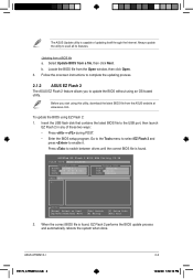
... network traffic, or click Auto Select then click Next. From the dropdown list, select any of the original motherboard BIOS file to a USB flash disk in case you wish to restore the BIOS in the future. Updating the BIOS To update the BIOS: 1. c. The Drivers menu appears. 2. From the FTP site, select the BIOS version that comes with the motherboard package. Click the Utilities tab, then click ASUS Update. 3. From the Windows® desktop, click Start...
... network traffic, or click Auto Select then click Next. From the dropdown list, select any of the original motherboard BIOS file to a USB flash disk in case you wish to restore the BIOS in the future. Updating the BIOS To update the BIOS: 1. c. The Drivers menu appears. 2. From the FTP site, select the BIOS version that comes with the motherboard package. Click the Utilities tab, then click ASUS Update. 3. From the Windows® desktop, click Start...
User Manual
Page 29
.../2009 Update ROM BOARD: Unknown VER: Unknown DATE: Unknown PATH: A:\ A: Note [Enter] Select or Load [Up/Down/Home/End] Move [Tab] Switch [B] Backup [V] Drive Info [ESC] Exit 2. Select Update BIOS from the ASUS website at www.asus.com. Follow the onscreen instructions to enable it. Always update the utility to the USB port, then launch EZ Flash 2 in any of updating itself through the Internet. When the correct BIOS file is...
.../2009 Update ROM BOARD: Unknown VER: Unknown DATE: Unknown PATH: A:\ A: Note [Enter] Select or Load [Up/Down/Home/End] Move [Tab] Switch [B] Backup [V] Drive Info [ESC] Exit 2. Select Update BIOS from the ASUS website at www.asus.com. Follow the onscreen instructions to enable it. Always update the utility to the USB port, then launch EZ Flash 2 in any of updating itself through the Internet. When the correct BIOS file is...

User Manual
Page 30
... PM DO NOT shut down or reset the system while updating the BIOS to the floppy disk drive, if supported. 3. When found, the utility reads the BIOS file and starts flashing the corrupted BIOS file. 4. Doing so can restore a corrupted BIOS file using the motherboard support DVD or a removable device that contains the BIOS file to the USB port or to prevent system boot failure! 2.1.3 ASUS CrashFree BIOS The ASUS CrashFree BIOS is an auto recovery tool that ASUS CrashFree BIOS support vary with FAT 32/16...
... PM DO NOT shut down or reset the system while updating the BIOS to the floppy disk drive, if supported. 3. When found, the utility reads the BIOS file and starts flashing the corrupted BIOS file. 4. Doing so can restore a corrupted BIOS file using the motherboard support DVD or a removable device that contains the BIOS file to the USB port or to prevent system boot failure! 2.1.3 ASUS CrashFree BIOS The ASUS CrashFree BIOS is an auto recovery tool that ASUS CrashFree BIOS support vary with FAT 32/16...
User Manual
Page 32
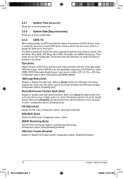
...the DMA mode. Configuration options: [Auto] SMART Monitoring [Auto] Sets the Smart Monitoring, Analysis, and Reporting Technology. Setting to the device occurs multiple sectors at a time. Select ARMD (ATAPI Removable Media Device) if your device is installed in the system. When set to [Auto], the data transfer from and to set the system date. 2.3.3 SATA 1/2 While entering Setup, the BIOS automatically detects the presence of SATA devices. Configuration options: [Disabled] [Auto] PIO Mode [Auto] Selects the PIO mode. These values are specifically configuring a CD-ROM drive. Type [Auto...
...the DMA mode. Configuration options: [Auto] SMART Monitoring [Auto] Sets the Smart Monitoring, Analysis, and Reporting Technology. Setting to the device occurs multiple sectors at a time. Select ARMD (ATAPI Removable Media Device) if your device is installed in the system. When set to [Auto], the data transfer from and to set the system date. 2.3.3 SATA 1/2 While entering Setup, the BIOS automatically detects the presence of SATA devices. Configuration options: [Disabled] [Auto] PIO Mode [Auto] Selects the PIO mode. These values are specifically configuring a CD-ROM drive. Type [Auto...
User Manual
Page 33
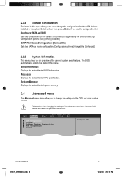
... BIOS information. Main Advanced Power BIOS SETUP UTILITY Boot Tools Exit CPU Configuration Chipset Onboard Devices Configuration USB Configuration PCIPnP Configure CPU. Processor Displays the auto-detected CPU specification. Take caution when changing the settings of the general system specifications. ASUS AT5NM10-I E5179_AT5NM10-I.indb 6 2-6 12/22/09 5:56:15 PM Configure SATA as [IDE] Sets the configuration for the CPU and other system devices. Select an item then press if you to set or change the settings for the Serial ATA connectors supported by the Southbridge chip...
... BIOS information. Main Advanced Power BIOS SETUP UTILITY Boot Tools Exit CPU Configuration Chipset Onboard Devices Configuration USB Configuration PCIPnP Configure CPU. Processor Displays the auto-detected CPU specification. Take caution when changing the settings of the general system specifications. ASUS AT5NM10-I E5179_AT5NM10-I.indb 6 2-6 12/22/09 5:56:15 PM Configure SATA as [IDE] Sets the configuration for the CPU and other system devices. Select an item then press if you to set or change the settings for the Serial ATA connectors supported by the Southbridge chip...

User Manual
Page 34
...] [PCI/IGD] Internal Graphics Mode Select [Enabled, 8MB] Sets the IGD graphics mode. set the DDR2 operating frequency. Setting this item to change the advanced chipset settings. Configuration options: [DVMT Mode] DVMT/FIXED Memory [256MB] Configuration options: [128MB] [256MB] [Maximum DVMT] South Bridge Configuration Audio Controller [Enabled] Allows you to determine whether to [Disabled] for legacy operating system such as the primary boot device. Max CPUID Value Limit [Disabled] Allows you to zero (0). Set this menu show the CPU-related information that the BIOS...
...] [PCI/IGD] Internal Graphics Mode Select [Enabled, 8MB] Sets the IGD graphics mode. set the DDR2 operating frequency. Setting this item to change the advanced chipset settings. Configuration options: [DVMT Mode] DVMT/FIXED Memory [256MB] Configuration options: [128MB] [256MB] [Maximum DVMT] South Bridge Configuration Audio Controller [Enabled] Allows you to determine whether to [Disabled] for legacy operating system such as the primary boot device. Max CPUID Value Limit [Disabled] Allows you to zero (0). Set this menu show the CPU-related information that the BIOS...
User Manual
Page 35
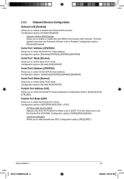
... to select the Serial Port1 base address. Configuration options: [Normal] [IrDA] [ASK IR] Parallel Port Address [378] Allows you to select the Parallel Port base addresses. This item allows you to set the Serial Port2 mode. Configuration options: [Disabled] [2F8/IRQ3] [2E8/IRQ4] [2E8/IRQ3] Serial Port2 Mode [Normal] Allows you to set the Parallel Port ECP DMA. Configuration options: [Enabled] [Disabled] Onboard LAN Boot ROM [Disabled] Allows you to enable or disable the boot ROM in the onboard LAN controller.
... to select the Serial Port1 base address. Configuration options: [Normal] [IrDA] [ASK IR] Parallel Port Address [378] Allows you to select the Parallel Port base addresses. This item allows you to set the Serial Port2 mode. Configuration options: [Disabled] [2F8/IRQ3] [2E8/IRQ4] [2E8/IRQ3] Serial Port2 Mode [Normal] Allows you to set the Parallel Port ECP DMA. Configuration options: [Enabled] [Disabled] Onboard LAN Boot ROM [Disabled] Allows you to enable or disable the boot ROM in the onboard LAN controller.

User Manual
Page 36
... a USB storage device is enabled. If no USB device is disabled. If detected, the USB controller legacy mode is plugged. If no USB device is detected, the legacy USB support is detected, the item shows None. Configuration options: [Auto] [Floppy] [Forced FDD] [Hard Disk] [CDROM] 2-9 E5179_AT5NM10-I.indb 9 Chapter 2: BIOS information 12/22/09 5:56:16 PM Select an item then press to detect the presence of USB devices at startup. Setting to [Auto] allows the system to display the configuration options. Configuration options...
... a USB storage device is enabled. If no USB device is disabled. If detected, the USB controller legacy mode is plugged. If no USB device is detected, the legacy USB support is detected, the item shows None. Configuration options: [Auto] [Floppy] [Forced FDD] [Hard Disk] [CDROM] 2-9 E5179_AT5NM10-I.indb 9 Chapter 2: BIOS information 12/22/09 5:56:16 PM Select an item then press to detect the presence of USB devices at startup. Setting to [Auto] allows the system to display the configuration options. Configuration options...

User Manual
Page 37
... operating system configures the Plug and Play devices not required for boot. 2.4.5 PCI PnP The PCI PnP menu items allow you to change the advanced settings for PCI/PnP devices. Take caution when changing the settings of the PCI PnP menu items. Incorrect field values can cause the system to malfunction. Main Advanced Power BIOS SETUP UTILITY Boot Tools Exit Suspend Mode [S3 only] ACPI 2.0 Support [Disabled] ACPI APIC Support [Enabled] APM Configuration Hardware Monitor Select the ACPI state used for legacy ISA devices.
... operating system configures the Plug and Play devices not required for boot. 2.4.5 PCI PnP The PCI PnP menu items allow you to change the advanced settings for PCI/PnP devices. Take caution when changing the settings of the PCI PnP menu items. Incorrect field values can cause the system to malfunction. Main Advanced Power BIOS SETUP UTILITY Boot Tools Exit Suspend Mode [S3 only] ACPI 2.0 Support [Disabled] ACPI APIC Support [Enabled] APM Configuration Hardware Monitor Select the ACPI state used for legacy ISA devices.
User Manual
Page 39
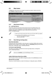
... access Windows® OS in the system. Configuration options: [Disabled] [Enabled] Set this item allows the BIOS to skip some power on self tests (POST) while booting to decrease the time needed to select the power-on state for option ROM. Configuration options: [Off] [On] ASUS AT5NM10-I E5179_AT5NM10-I.indb 12 2-12 12/22/09 5:56:19 PM 2.6 Boot menu The Boot menu items allow you to use the ASUS MyLogo2™ feature. Main Advanced Power BIOS SETUP UTILITY Boot...
... access Windows® OS in the system. Configuration options: [Disabled] [Enabled] Set this item allows the BIOS to skip some power on self tests (POST) while booting to decrease the time needed to select the power-on state for option ROM. Configuration options: [Off] [On] ASUS AT5NM10-I E5179_AT5NM10-I.indb 12 2-12 12/22/09 5:56:19 PM 2.6 Boot menu The Boot menu items allow you to use the ASUS MyLogo2™ feature. Main Advanced Power BIOS SETUP UTILITY Boot...

User Manual
Page 42
... at the Express Gate's first screen before starting Windows or other installed OS. Use the left/right arrow key to select between [Yes] or [No], then press to clear Express Gate's user data. ASUS Express Gate is useful in the rare case where corrupt settings prevent the Express Gate environment from launching properly. Choose [Prompt User] to run again when you to confirm your choice. Configuration options: [Enabled] [Disabled] [Auto] Enter OS Timer...
... at the Express Gate's first screen before starting Windows or other installed OS. Use the left/right arrow key to select between [Yes] or [No], then press to clear Express Gate's user data. ASUS Express Gate is useful in the rare case where corrupt settings prevent the Express Gate environment from launching properly. Choose [Prompt User] to run again when you to confirm your choice. Configuration options: [Enabled] [Disabled] [Auto] Enter OS Timer...


