AT3IONT-I Series user's manual
Page 3
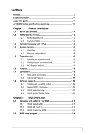
Contents Notices...v Safety information vi About this guide vi AT3IONT-I Series specifications summary viii Chapter 1: Product introduction 1.1 Before you proceed 1-1 1.2 Motherboard overview 1-2 1.2.1 Motherboard layout 1-2 ... 1-11 1.8 Software support 1-16 1.8.1 Installing an operating system 1-16 1.8.2 Support DVD information 1-16 1.8.3 ASUS VideoSecurity 1-17 1.8.4 ASUS Home Theater Gate 1-19 Chapter 2: BIOS information 2.1 Managing and updating your BIOS 2-1 2.1.1 ASUS Update utility 2-1 2.1.2 ASUS EZ Flash 2 2-2 2.1.3 ASUS CrashFree BIOS 2-3 2.2 BIOS setup program 2-4 iii
Contents Notices...v Safety information vi About this guide vi AT3IONT-I Series specifications summary viii Chapter 1: Product introduction 1.1 Before you proceed 1-1 1.2 Motherboard overview 1-2 1.2.1 Motherboard layout 1-2 ... 1-11 1.8 Software support 1-16 1.8.1 Installing an operating system 1-16 1.8.2 Support DVD information 1-16 1.8.3 ASUS VideoSecurity 1-17 1.8.4 ASUS Home Theater Gate 1-19 Chapter 2: BIOS information 2.1 Managing and updating your BIOS 2-1 2.1.1 ASUS Update utility 2-1 2.1.2 ASUS EZ Flash 2 2-2 2.1.3 ASUS CrashFree BIOS 2-3 2.2 BIOS setup program 2-4 iii

AT3IONT-I Series user's manual
Page 6
...8226; Chapter 1: Product introduction This chapter describes the features of the motherboard and the new technology it supports. • Chapter 2: BIOS information This chapter tells how to fix it by yourself. Detailed descriptions of the electrical outlet you need when installing and configuring the ...motherboard. vi If you are not sure about the voltage of the BIOS parameters are using the product, ensure that came with the product, contact a qualified service technician or your retailer. Contact a ...
...8226; Chapter 1: Product introduction This chapter describes the features of the motherboard and the new technology it supports. • Chapter 2: BIOS information This chapter tells how to fix it by yourself. Detailed descriptions of the electrical outlet you need when installing and configuring the ...motherboard. vi If you are not sure about the voltage of the BIOS parameters are using the product, ensure that came with the product, contact a qualified service technician or your retailer. Contact a ...

AT3IONT-I Series user's manual
Page 8
... maximum of 4GB capacity or more, the operating system may only recognize less than 3GB. AT3IONT-I Series specifications summary CPU Chipset Front Side Bus Memory Graphics Expansion slot Storage Audio LAN USB ASUS special features Integrated Dual-Core Intel® Atom™ 330 processor NVIDIA® ION™... 1066/800 MHz DDR3 memory modules * Refer to 10 USB 2.0/1.1 ports (4 ports at mid-board, 6 ports at back panel) ASUS CrashFree BIOS 3 ASUS EZ Flash 2 ASUS MyLogo 2™ ASUS AI NET 2 ASUS Express Gate Home Theater Gate ASUS Q-Fan Stack Cool3+ (continued on the next page) viii
... maximum of 4GB capacity or more, the operating system may only recognize less than 3GB. AT3IONT-I Series specifications summary CPU Chipset Front Side Bus Memory Graphics Expansion slot Storage Audio LAN USB ASUS special features Integrated Dual-Core Intel® Atom™ 330 processor NVIDIA® ION™... 1066/800 MHz DDR3 memory modules * Refer to 10 USB 2.0/1.1 ports (4 ports at mid-board, 6 ports at back panel) ASUS CrashFree BIOS 3 ASUS EZ Flash 2 ASUS MyLogo 2™ ASUS AI NET 2 ASUS Express Gate Home Theater Gate ASUS Q-Fan Stack Cool3+ (continued on the next page) viii

AT3IONT-I Series user's manual
Page 9
... panel audio connector 1 x COM connector 1 x Chassis intrusion connector 1 x SATA power connector* 1 x 24-pin EATX power connector** * For AT3IONT-I DELUXE only ** For AT3IONT-I only 8 Mb Flash ROM, AMI BIOS, PnP, DMI2.0, WfM2.0, SMBIOS 2.5, ACPI v2.0a 2 x Serial ATA cables 1 x I/O shield 1 x User Manual 1 x SATA Power ...cable* 1 x Remote Controller* 1 x Receiver* 1 x WiFi antenna* 1 x 90W DC adapter* 1 x Power cord* * For AT3IONT-I DELUXE only Drivers ASUS PC Probe II ASUS ...
... panel audio connector 1 x COM connector 1 x Chassis intrusion connector 1 x SATA power connector* 1 x 24-pin EATX power connector** * For AT3IONT-I DELUXE only ** For AT3IONT-I only 8 Mb Flash ROM, AMI BIOS, PnP, DMI2.0, WfM2.0, SMBIOS 2.5, ACPI v2.0a 2 x Serial ATA cables 1 x I/O shield 1 x User Manual 1 x SATA Power ...cable* 1 x Remote Controller* 1 x Receiver* 1 x WiFi antenna* 1 x 90W DC adapter* 1 x Power cord* * For AT3IONT-I DELUXE only Drivers ASUS PC Probe II ASUS ...

AT3IONT-I Series user's manual
Page 11
... DIMM slots 5. Atom 330 processor 4. SATA power connectors (4-pin SATA_PWR1) 6. 1.2 1.2.1 Motherboard overview Motherboard layout ASUS AT3IONT-I Series motherboards include AT3IONT-I and AT3IONT-I DELUXE Lithium Cell CMOS Power DDR3 DIMM_A1 (64bit, 240-pin module) BT_USB34 LAN1_USB12 RCA_OUT AUDIO RTL 8112L AAFP ...ALC 887 USB910 USB78 NVIDIA® ION WLAN PCIEX16 SATA2 SATA4 SATA1 SATA3 SB_PWR CLRTC F_PANEL CHASSIS 6 7 8Mb BIOS...
... DIMM slots 5. Atom 330 processor 4. SATA power connectors (4-pin SATA_PWR1) 6. 1.2 1.2.1 Motherboard overview Motherboard layout ASUS AT3IONT-I Series motherboards include AT3IONT-I and AT3IONT-I DELUXE Lithium Cell CMOS Power DDR3 DIMM_A1 (64bit, 240-pin module) BT_USB34 LAN1_USB12 RCA_OUT AUDIO RTL 8112L AAFP ...ALC 887 USB910 USB78 NVIDIA® ION WLAN PCIEX16 SATA2 SATA4 SATA1 SATA3 SB_PWR CLRTC F_PANEL CHASSIS 6 7 8Mb BIOS...

AT3IONT-I Series user's manual
Page 16
... that came with the slot and press firmly until the card is already installed in a chassis). 3. Install the software drivers for information on BIOS setup. 2. The following sub‑sections describe the slot and the expansion cards that you intend to do so may need to the card....expansion card: 1. Failure to use . 4. Remove the system unit cover (if your motherboard is completely seated on the system and change the necessary BIOS settings, if any. Align the card connector with it and make the necessary hardware settings for later use . Turn on the slot. 5. Before ...
... that came with the slot and press firmly until the card is already installed in a chassis). 3. Install the software drivers for information on BIOS setup. 2. The following sub‑sections describe the slot and the expansion cards that you intend to do so may need to the card....expansion card: 1. Failure to use . 4. Remove the system unit cover (if your motherboard is completely seated on the system and change the necessary BIOS settings, if any. Align the card connector with it and make the necessary hardware settings for later use . Turn on the slot. 5. Before ...
AT3IONT-I Series user's manual
Page 17
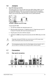
... the boot process and enter BIOS setup to pins 2-3. After clearing the CMOS, reinstall the battery. 1.7 Connectors 1.7.1 Rear panel connectors 1 2 3 4 5 6 78 16 15 14 13 12 11 10 9 ASUS AT3IONT-I SERIES Clear RTC RAM To erase the RTC RAM: 1. AT3IONT-I DELUXE 12 23 CLRTC Normal... (Default) Clear RTC AT3IONT-I Series 1-8 Plug the power cord and turn ON the computer. 4. If the steps above ...
... the boot process and enter BIOS setup to pins 2-3. After clearing the CMOS, reinstall the battery. 1.7 Connectors 1.7.1 Rear panel connectors 1 2 3 4 5 6 78 16 15 14 13 12 11 10 9 ASUS AT3IONT-I SERIES Clear RTC RAM To erase the RTC RAM: 1. AT3IONT-I DELUXE 12 23 CLRTC Normal... (Default) Clear RTC AT3IONT-I Series 1-8 Plug the power cord and turn ON the computer. 4. If the steps above ...

AT3IONT-I Series user's manual
Page 20
... GND RSATA_RXN1 RSATA_RXP1 GND RSATA_TXN1 RSATA_TXP1 GND GND RSATA_TXP3 RSATA_TXN3 GND RSATA_RXP3 RSATA_RXN3 GND AT3IONT-I DELUXE SATA2 GND RSATA_RXN2 RSATA_RXP2 GND RSATA_TXN2 RSATA_TXP2 GND SATA4 GND RSATA_TXP4 RSATA_TXN4 GND RSATA_RXP4 RSATA_RXN4 GND AT3IONT-I SERIES SATA connectors • Install the Windows® XP Service Pack 2...174; XP operating system on RAID/AHCI, refer to the RAID/AHCI Supplementary Guide included in the folder named Manual in the BIOS to other media such as a USB flash disk and load RAID driver during installing Windows® Vista OS with the Serial ATA...
... GND RSATA_RXN1 RSATA_RXP1 GND RSATA_TXN1 RSATA_TXP1 GND GND RSATA_TXP3 RSATA_TXN3 GND RSATA_RXP3 RSATA_RXN3 GND AT3IONT-I DELUXE SATA2 GND RSATA_RXN2 RSATA_RXP2 GND RSATA_TXN2 RSATA_TXP2 GND SATA4 GND RSATA_TXP4 RSATA_TXN4 GND RSATA_RXP4 RSATA_RXN4 GND AT3IONT-I SERIES SATA connectors • Install the Windows® XP Service Pack 2...174; XP operating system on RAID/AHCI, refer to the RAID/AHCI Supplementary Guide included in the folder named Manual in the BIOS to other media such as a USB flash disk and load RAID driver during installing Windows® Vista OS with the Serial ATA...

AT3IONT-I Series user's manual
Page 22
...definition compliant definition AT3IONT-I SERIES fan connectors 5. If you want to connect an AC'97 front panel audio module to this connector is for details. 1-13 Chapter 1: Product introduction By default, this connector, set the Front Panel Select item in the BIOS setup to this ...air flow inside the system may damage the motherboard components. 4. CPU_FAN Rotation +12V GND PWR_FAN Rotation +12V GND CHA_FAN Rotation +12V GND AT3IONT-I SERIES Analog front panel connector • We recommend that you connect a high-definition front panel audio module to this connector to avail...
...definition compliant definition AT3IONT-I SERIES fan connectors 5. If you want to connect an AC'97 front panel audio module to this connector is for details. 1-13 Chapter 1: Product introduction By default, this connector, set the Front Panel Select item in the BIOS setup to this ...air flow inside the system may damage the motherboard components. 4. CPU_FAN Rotation +12V GND PWR_FAN Rotation +12V GND CHA_FAN Rotation +12V GND AT3IONT-I SERIES Analog front panel connector • We recommend that you connect a high-definition front panel audio module to this connector to avail...
AT3IONT-I Series user's manual
Page 31
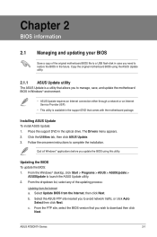
... case you wish to download then click Next. ASUS AT3IONT-I Series 2-1 From the FTP site, select the BIOS version that comes with the motherboard package. Follow the onscreen instructions to launch the ASUS Update utility. 2. Updating the BIOS To update the BIOS: 1. Chapter 2 BIOS information 2.1 Managing and updating your BIOS Save a copy of the updating process: Updating from...
... case you wish to download then click Next. ASUS AT3IONT-I Series 2-1 From the FTP site, select the BIOS version that comes with the motherboard package. Follow the onscreen instructions to launch the ASUS Update utility. 2. Updating the BIOS To update the BIOS: 1. Chapter 2 BIOS information 2.1 Managing and updating your BIOS Save a copy of the updating process: Updating from...

AT3IONT-I Series user's manual
Page 32
... ways: • Press + during POST. • Enter the BIOS setup program. Updating from the Open window, then click Open. 3. The ASUS Update utility is found . Press to enable it. ASUSTek EZ Flash 2 BIOS ROM Utility V3.38 FLASH TYPE: MXIC 25L8005 Current ROM BOARD: AT3IONT-I Series VER: 0207 (H:00 B:05) DATE: 12/29/2009...
... ways: • Press + during POST. • Enter the BIOS setup program. Updating from the Open window, then click Open. 3. The ASUS Update utility is found . Press to enable it. ASUSTek EZ Flash 2 BIOS ROM Utility V3.38 FLASH TYPE: MXIC 25L8005 Current ROM BOARD: AT3IONT-I Series VER: 0207 (H:00 B:05) DATE: 12/29/2009...

AT3IONT-I Series user's manual
Page 33
... prevent system boot failure! 2.1.3 ASUS CrashFree BIOS The ASUS CrashFree BIOS is an auto recovery tool that contains the BIOS file to the USB port or to ensure system compatibility and stability. You can cause system boot failure! When found, the utility reads the BIOS file and starts flashing the corrupted BIOS file. 4. ASUS AT3IONT-I Series 2-3 Ensure to load...
... prevent system boot failure! 2.1.3 ASUS CrashFree BIOS The ASUS CrashFree BIOS is an auto recovery tool that contains the BIOS file to the USB port or to ensure system compatibility and stability. You can cause system boot failure! When found, the utility reads the BIOS file and starts flashing the corrupted BIOS file. 4. ASUS AT3IONT-I Series 2-3 Ensure to load...
AT3IONT-I Series user's manual
Page 34
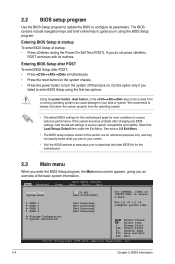
... may not exactly match what you failed to your screen. • Visit the ASUS website at startup: • Press during the Power-On Self Test (POST). Storage Configuration System Information Select Screen Select Item +- 2.2 BIOS setup program Use the BIOS Setup program to ensure system compatibility and stability. Do this section are for...
... may not exactly match what you failed to your screen. • Visit the ASUS website at startup: • Press during the Power-On Self Test (POST). Storage Configuration System Information Select Screen Select Item +- 2.2 BIOS setup program Use the BIOS Setup program to ensure system compatibility and stability. Do this section are for...
AT3IONT-I Series user's manual
Page 35
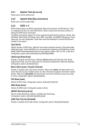
...LBA mode disabled. Select CDROM if you to set the system date. 2.3.3 SATA 1~4 While entering Setup, the BIOS automatically detects the presence of SATA drive. Setting to display the SATA device information. Configuration options: [Disabled] [...Auto] Block (Multi-sector Transfer) M [Auto] Enables or disables data multi-sectors transfers. The BIOS automatically detects the values opposite the dimmed items (Device, Vendor, Size, LBA Mode, Block Mode, PIO Mode, Async... appropriate SATA device type. Configuration options: [Disabled] [Enabled] ASUS AT3IONT-I Series 2-5
...LBA mode disabled. Select CDROM if you to set the system date. 2.3.3 SATA 1~4 While entering Setup, the BIOS automatically detects the presence of SATA drive. Setting to display the SATA device information. Configuration options: [Disabled] [...Auto] Block (Multi-sector Transfer) M [Auto] Enables or disables data multi-sectors transfers. The BIOS automatically detects the values opposite the dimmed items (Device, Vendor, Size, LBA Mode, Block Mode, PIO Mode, Async... appropriate SATA device type. Configuration options: [Disabled] [Enabled] ASUS AT3IONT-I Series 2-5

AT3IONT-I Series user's manual
Page 36
...] [Enabled] IDE Detect Time Out (Sec) [5] Selects the time out value for the CPU and other system devices. BIOS Information Displays the auto-detected BIOS information. System Memory Displays the auto-detected system memory. 2.4 Advanced menu The Advanced menu items allow you to change the ... Hard Disk Write Protect [Disabled] Disables or enables device write protection. This will be effective only if device is accessed through BIOS. The BIOS automatically detects the items in this menu allow you to set the OnChip SATA Controller item to set the OnChip SATA mode....
...] [Enabled] IDE Detect Time Out (Sec) [5] Selects the time out value for the CPU and other system devices. BIOS Information Displays the auto-detected BIOS information. System Memory Displays the auto-detected system memory. 2.4 Advanced menu The Advanced menu items allow you to change the ... Hard Disk Write Protect [Disabled] Disables or enables device write protection. This will be effective only if device is accessed through BIOS. The BIOS automatically detects the items in this menu allow you to set the OnChip SATA Controller item to set the OnChip SATA mode....

AT3IONT-I Series user's manual
Page 37
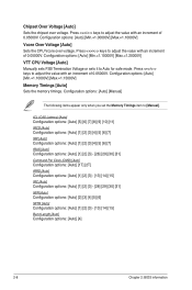
...adjust the value with an increment of GPU overclocking options to [Manual]. Configuration options: [Auto] [Min.=1.21000V] [Max.=2.47000V] ASUS AT3IONT-I Series 2-7 iGPU OverClock [450] Allows you to limit CPUID maximum value. Configuration options: [Disabled] [Enabled] Hyper Threading Technology...system such as Windows NT4.0. Max CPUID Value Limit [Disabled] Allows you set this menu show the CPU-related information that the BIOS automatically detects. Configuration options: [Auto] [Linked] [Unlinked] [Profiled] iGPU OverClock Mode [Auto] Allows selection of 1.02000V. ...
...adjust the value with an increment of GPU overclocking options to [Manual]. Configuration options: [Auto] [Min.=1.21000V] [Max.=2.47000V] ASUS AT3IONT-I Series 2-7 iGPU OverClock [450] Allows you to limit CPUID maximum value. Configuration options: [Disabled] [Enabled] Hyper Threading Technology...system such as Windows NT4.0. Max CPUID Value Limit [Disabled] Allows you set this menu show the CPU-related information that the BIOS automatically detects. Configuration options: [Auto] [Linked] [Unlinked] [Profiled] iGPU OverClock Mode [Auto] Allows selection of 1.02000V. ...
AT3IONT-I Series user's manual
Page 38
...: [Auto] [1] [2] [3] - [28] [29] [30] [31] tWR [Auto] Configuration options: [Auto] [2] [3] [4] [5] [6] tWTR [Auto] Configuration options: [Auto] [1] [2] [3] - [13] [14] [15] Burst Length [Auto] Configuration options: [Auto] [4] 2-8 Chapter 2: BIOS information Press / keys to adjust the value with an increment of 0.05000V. Configuration options: [Auto] [Manual] The following items appear only when you set the...
...: [Auto] [1] [2] [3] - [28] [29] [30] [31] tWR [Auto] Configuration options: [Auto] [2] [3] [4] [5] [6] tWTR [Auto] Configuration options: [Auto] [1] [2] [3] - [13] [14] [15] Burst Length [Auto] Configuration options: [Auto] [4] 2-8 Chapter 2: BIOS information Press / keys to adjust the value with an increment of 0.05000V. Configuration options: [Auto] [Manual] The following items appear only when you set the...

AT3IONT-I Series user's manual
Page 40
...: [10 Sec] [20 Sec] [30 Sec] [40 Sec] Emulation Type [Auto] Allows you to set the maximum time that the BIOS waits for Legacy USB storage devices, including USB flash drives and USB hard drives. Configuration options: [Enabled] [Disabled] Legacy USB Support [Auto...USB controller legacy mode is detected, the item shows None. Configuration options: [Auto] [Floppy] [Forced FDD] [Hard Disk] [CDROM] 2-10 Chapter 2: BIOS information Configuration options: [Disabled] [Enabled] [Auto] USB 2.0 Controller Mode [HiSpeed] Allows you to configure the USB 2.0 controller in this menu allows you...
...: [10 Sec] [20 Sec] [30 Sec] [40 Sec] Emulation Type [Auto] Allows you to set the maximum time that the BIOS waits for Legacy USB storage devices, including USB flash drives and USB hard drives. Configuration options: [Enabled] [Disabled] Legacy USB Support [Auto...USB controller legacy mode is detected, the item shows None. Configuration options: [Auto] [Floppy] [Forced FDD] [Hard Disk] [CDROM] 2-10 Chapter 2: BIOS information Configuration options: [Disabled] [Enabled] [Auto] USB 2.0 Controller Mode [HiSpeed] Allows you to configure the USB 2.0 controller in this menu allows you...
AT3IONT-I Series user's manual
Page 41
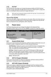
... options: [S1 (POS) Only] [S3 Only] [Auto] [S1(POS) Only] - When set to [No], BIOS configures all the devices in the S1 state. Main Advanced Power BIOS SETUP UTILITY Boot Tools Exit Suspend Mode ACPI 2.0 Support ACPI APIC Support Control EuP [Auto] [Disabled] [Enabled] [Disabled... to its working state exactly where it was left off and consumes less power than in the system. Configuration options: [Disabled] [Enabled] ASUS AT3IONT-I Series 2-11 Configuration options: [No] [Yes] 2.5 Power menu The Power menu items allow you to enable or disable the Advanced Configuration...
... options: [S1 (POS) Only] [S3 Only] [Auto] [S1(POS) Only] - When set to [No], BIOS configures all the devices in the S1 state. Main Advanced Power BIOS SETUP UTILITY Boot Tools Exit Suspend Mode ACPI 2.0 Support ACPI APIC Support Control EuP [Auto] [Disabled] [Enabled] [Disabled... to its working state exactly where it was left off and consumes less power than in the system. Configuration options: [Disabled] [Enabled] ASUS AT3IONT-I Series 2-11 Configuration options: [No] [Yes] 2.5 Power menu The Power menu items allow you to enable or disable the Advanced Configuration...

AT3IONT-I Series user's manual
Page 42
..., 3.3V Voltage, 5V Voltage, 12V Voltage [xxxV] or [Ignored] The onboard hardware monitor automatically detects the voltage output through the onboard voltage regulators. 2-12 Chapter 2: BIOS information If the fan is set to Enabled, the items RTC Alarm Date, RTC Alarm Hour, RTC Alarm Minute, and RTC Alarm Second appear with...
..., 3.3V Voltage, 5V Voltage, 12V Voltage [xxxV] or [Ignored] The onboard hardware monitor automatically detects the voltage output through the onboard voltage regulators. 2-12 Chapter 2: BIOS information If the fan is set to Enabled, the items RTC Alarm Date, RTC Alarm Hour, RTC Alarm Minute, and RTC Alarm Second appear with...


