AT3IONT-I Series user's manual
Page 3
Contents Notices...v Safety information vi About this guide vi AT3IONT-I Series specifications summary viii Chapter 1: Product introduction 1.1 Before you proceed 1-1 1.2 Motherboard overview 1-2 1.2.1 Motherboard layout 1-2 1.2.2 Layout contents 1-2 1.3 Central Processing Unit (CPU ... 1-8 1.7.1 Rear panel connectors 1-8 1.7.2 Internal connectors 1-11 1.8 Software support 1-16 1.8.1 Installing an operating system 1-16 1.8.2 Support DVD information 1-16 1.8.3 ASUS VideoSecurity 1-17 1.8.4 ASUS Home Theater Gate 1-19 Chapter 2: BIOS information 2.1 Managing and updating your BIOS...
Contents Notices...v Safety information vi About this guide vi AT3IONT-I Series specifications summary viii Chapter 1: Product introduction 1.1 Before you proceed 1-1 1.2 Motherboard overview 1-2 1.2.1 Motherboard layout 1-2 1.2.2 Layout contents 1-2 1.3 Central Processing Unit (CPU ... 1-8 1.7.1 Rear panel connectors 1-8 1.7.2 Internal connectors 1-11 1.8 Software support 1-16 1.8.1 Installing an operating system 1-16 1.8.2 Support DVD information 1-16 1.8.3 ASUS VideoSecurity 1-17 1.8.4 ASUS Home Theater Gate 1-19 Chapter 2: BIOS information 2.1 Managing and updating your BIOS...

AT3IONT-I Series user's manual
Page 10
... supply is switched off mode. Before you for the list of accessories. • AT3IONT-I Series motherboards include AT3IONT-I and AT3IONT-I SERIES Onboard LED 1-1 Chapter 1: Product introduction Failure to do so may cause severe damage to page ix for buying an ASUS® AT3IONT-I Series motherboard! This is detached from models. • If any component, ensure...
... supply is switched off mode. Before you for the list of accessories. • AT3IONT-I Series motherboards include AT3IONT-I and AT3IONT-I SERIES Onboard LED 1-1 Chapter 1: Product introduction Failure to do so may cause severe damage to page ix for buying an ASUS® AT3IONT-I Series motherboard! This is detached from models. • If any component, ensure...

AT3IONT-I Series user's manual
Page 11
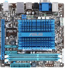
1.2 1.2.1 Motherboard overview Motherboard layout ASUS AT3IONT-I Series motherboards include AT3IONT-I and AT3IONT-I DELUXE two models The layout varies with external ports goes to the chassis. PWR_FAN Atom 330 CHA_FAN SPDIF_O 17.1cm(6.75in) DDR3 DIMM_A2 (64bit, 240-pin module) AT3IONT-I DELUXE Lithium Cell CMOS Power DDR3 DIMM_A1 (...) Front panel audio connector (10-1 pin AAFP) USB connector (10-1 pin USB78, USB910) Page 1-14 1-8 1-1 1-11 1-13 1-12 ASUS AT3IONT-I DELUXE only. The edge with models. DO NOT overtighten the screws! Atom 330 processor 4. DDR3 DIMM slots 5.
1.2 1.2.1 Motherboard overview Motherboard layout ASUS AT3IONT-I Series motherboards include AT3IONT-I and AT3IONT-I DELUXE two models The layout varies with external ports goes to the chassis. PWR_FAN Atom 330 CHA_FAN SPDIF_O 17.1cm(6.75in) DDR3 DIMM_A2 (64bit, 240-pin module) AT3IONT-I DELUXE Lithium Cell CMOS Power DDR3 DIMM_A1 (...) Front panel audio connector (10-1 pin AAFP) USB connector (10-1 pin USB78, USB910) Page 1-14 1-8 1-1 1-11 1-13 1-12 ASUS AT3IONT-I DELUXE only. The edge with models. DO NOT overtighten the screws! Atom 330 processor 4. DDR3 DIMM slots 5.
AT3IONT-I Series user's manual
Page 13
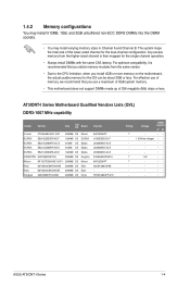
... support A* B* - •• 1.35V(low voltage) • • - •• - •• - •• 1.5V •• - •• - •• - •• - •• ASUS AT3IONT-I Series Motherboard Qualified Vendors Lists (QVL) DDR3-1067 MHz capability Vendor Part No. The system maps the total size of 256 megabits (Mb) chips or...
... support A* B* - •• 1.35V(low voltage) • • - •• - •• - •• 1.5V •• - •• - •• - •• - •• ASUS AT3IONT-I Series Motherboard Qualified Vendors Lists (QVL) DDR3-1067 MHz capability Vendor Part No. The system maps the total size of 256 megabits (Mb) chips or...
AT3IONT-I Series user's manual
Page 15
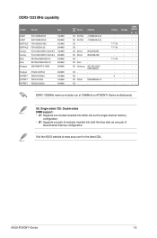
...Supports one pair of modules inserted into both the blue slots as one pair of dual-channel memory configuration. Visit the ASUS website at 1066MHz on AT3IONT-I Series 1-6 Timing 7-7-7-20 7-7-7-20 7-7-7-20 - Size ASINT ASINT BUFFALO BUFFALO Century Century Elixir Elixir Kingtiger SLY3128M8-EDJE ...support A* B - - •• 9 - •• - - •• - - •• DDR3 1333MHz memory modules run at www.asus.com for the latest QVL. DDR3-1333 MHz capability Vendor Part No. SS ELPIDA DS ELPIDA SS DS SS Micron DS Micron DS DS Elixir...
...Supports one pair of modules inserted into both the blue slots as one pair of dual-channel memory configuration. Visit the ASUS website at 1066MHz on AT3IONT-I Series 1-6 Timing 7-7-7-20 7-7-7-20 7-7-7-20 - Size ASINT ASINT BUFFALO BUFFALO Century Century Elixir Elixir Kingtiger SLY3128M8-EDJE ...support A* B - - •• 9 - •• - - •• - - •• DDR3 1333MHz memory modules run at www.asus.com for the latest QVL. DDR3-1333 MHz capability Vendor Part No. SS ELPIDA DS ELPIDA SS DS SS Micron DS Micron DS DS Elixir...
AT3IONT-I Series user's manual
Page 17
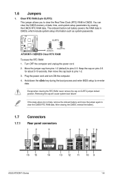
... 1-8 After clearing the CMOS, reinstall the battery. 1.7 Connectors 1.7.1 Rear panel connectors 1 2 3 4 5 6 78 16 15 14 13 12 11 10 9 ASUS AT3IONT-I SERIES Clear RTC RAM To erase the RTC RAM: 1. Clear RTC RAM (3-pin CLRTC) This jumper allows you to pins 1-2. 3. If the steps above do ...
... 1-8 After clearing the CMOS, reinstall the battery. 1.7 Connectors 1.7.1 Rear panel connectors 1 2 3 4 5 6 78 16 15 14 13 12 11 10 9 ASUS AT3IONT-I SERIES Clear RTC RAM To erase the RTC RAM: 1. Clear RTC RAM (3-pin CLRTC) This jumper allows you to pins 1-2. 3. If the steps above do ...
AT3IONT-I Series user's manual
Page 19
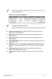
DC power port (for USB 2.0 devices. 13. These two 4-pin Universal Serial Bus (USB) ports are for AT3IONT-I DELUXE only). This port connects to an external audio output device via an RCA cable. 11. Optical S/PDIF Out port. HDMI port. ...are available for USB 2.0 devices. 12. USB 2.0 ports 3 and 4. These two 4-pin Universal Serial Bus (USB) ports are for connecting USB 2.0 devices. 16. ASUS AT3IONT-I DELUXE only). RCA Out port (left-channel) (for a High-Definition Multimedia Interface (HDMI) connector, and is HDCP compliant allowing playback of the audio ports in...
DC power port (for USB 2.0 devices. 13. These two 4-pin Universal Serial Bus (USB) ports are for AT3IONT-I DELUXE only). This port connects to an external audio output device via an RCA cable. 11. Optical S/PDIF Out port. HDMI port. ...are available for USB 2.0 devices. 12. USB 2.0 ports 3 and 4. These two 4-pin Universal Serial Bus (USB) ports are for connecting USB 2.0 devices. 16. ASUS AT3IONT-I DELUXE only). RCA Out port (left-channel) (for a High-Definition Multimedia Interface (HDMI) connector, and is HDCP compliant allowing playback of the audio ports in...
AT3IONT-I Series user's manual
Page 21
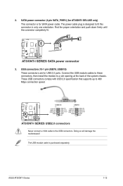
...the USB module cables to these connectors, then install the module to 480 Mbps connection speed. ASUS AT3IONT-I SERIES USB2.0 connectors Never connect a 1394 cable to fit this connector in only one orientation. AT3IONT-I DELUXE USB910 USB78 PIN 1 USB+5V USB_P9USB_P9+ GND USB+5V USB_P10USB_P10+ GND NC PIN ...1 USB+5V USB_P7USB_P7+ GND USB+5V USB_P8USB_P8+ GND NC AT3IONT-I Series 1-12 USB connectors (10-1 pin USB78, USB910) These connectors are for SATA power cable. Doing so will damage the motherboard...
...the USB module cables to these connectors, then install the module to 480 Mbps connection speed. ASUS AT3IONT-I SERIES USB2.0 connectors Never connect a 1394 cable to fit this connector in only one orientation. AT3IONT-I DELUXE USB910 USB78 PIN 1 USB+5V USB_P9USB_P9+ GND USB+5V USB_P10USB_P10+ GND NC PIN ...1 USB+5V USB_P7USB_P7+ GND USB+5V USB_P8USB_P8+ GND NC AT3IONT-I Series 1-12 USB connectors (10-1 pin USB78, USB910) These connectors are for SATA power cable. Doing so will damage the motherboard...
AT3IONT-I Series user's manual
Page 23
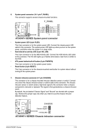
... 2-pin connector is removed or replaced. The signal is for the system power LED. F_PANEL AT3IONT-I DELUXE PWR LED PWR BTN PIN 1 HD_LED RESET GND PWR PLEDPLED+ Reset Ground IDE_LEDIDE_LED+ AT3IONT-I Series 1-14 The HD LED lights up when you intend to the HDD. •... up or flashes when data is read from or written to use the chassis intrusion detection feature. AT3IONT-I DELUXE CHASSIS GND Chassis Signal +5VSB_MB AT3IONT-I SERIES Chassis intrusion connector ASUS AT3IONT-I SERIES System panel connector • System power LED (2-pin PLED) This 2-pin connector is for...
... 2-pin connector is removed or replaced. The signal is for the system power LED. F_PANEL AT3IONT-I DELUXE PWR LED PWR BTN PIN 1 HD_LED RESET GND PWR PLEDPLED+ Reset Ground IDE_LEDIDE_LED+ AT3IONT-I Series 1-14 The HD LED lights up when you intend to the HDD. •... up or flashes when data is read from or written to use the chassis intrusion detection feature. AT3IONT-I DELUXE CHASSIS GND Chassis Signal +5VSB_MB AT3IONT-I SERIES Chassis intrusion connector ASUS AT3IONT-I SERIES System panel connector • System power LED (2-pin PLED) This 2-pin connector is for...
AT3IONT-I Series user's manual
Page 25
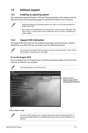
...To run the DVD. The following screen is NOT enabled in your computer, browse the contents of the Support DVD to change at www.asus.com for reference only. The contents of your OS documentation for detailed information. • Ensure that you install Windows® XP Service ...BIN folder. Click an icon to display Support DVD/ motherboard information Click an item to install If Autorun is for updates. ASUS AT3IONT-I Series 1-16 Visit the ASUS website at any time without notice. Double-click the ASSETUP.EXE to avail all motherboard features. Refer to your hardware. •...
...To run the DVD. The following screen is NOT enabled in your computer, browse the contents of the Support DVD to change at www.asus.com for reference only. The contents of your OS documentation for detailed information. • Ensure that you install Windows® XP Service ...BIN folder. Click an icon to display Support DVD/ motherboard information Click an item to install If Autorun is for updates. ASUS AT3IONT-I Series 1-16 Visit the ASUS website at any time without notice. Double-click the ASSETUP.EXE to avail all motherboard features. Refer to your hardware. •...
AT3IONT-I Series user's manual
Page 27
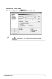
Click for the main screen to refer to the Help file for details on how to setup VideoSecurity. VideoSecurity Setting screen To launch the setting screen, click from the main screen. ASUS AT3IONT-I Series 1-18
Click for the main screen to refer to the Help file for details on how to setup VideoSecurity. VideoSecurity Setting screen To launch the setting screen, click from the main screen. ASUS AT3IONT-I Series 1-18

AT3IONT-I Series user's manual
Page 29
...=en-us for the latest supported type. • Due to Window® XP limitation, you have to install the UDF Reader to that channel number. ASUS AT3IONT-I Series 1-20 Internet Radio channel setting Long press the channel number and the station information on t�h�e��c�u�r�r�e�...;it�t�h�e��A�S��U�S���w�e�b��s�it�e��a�t http://support.asus.com/download/download.
...=en-us for the latest supported type. • Due to Window® XP limitation, you have to install the UDF Reader to that channel number. ASUS AT3IONT-I Series 1-20 Internet Radio channel setting Long press the channel number and the station information on t�h�e��c�u�r�r�e�...;it�t�h�e��A�S��U�S���w�e�b��s�it�e��a�t http://support.asus.com/download/download.
AT3IONT-I Series user's manual
Page 31
... utility. 2. Updating the BIOS To update the BIOS: 1. From the Windows® desktop, click Start > Programs > ASUS > ASUSUpdate > ASUSUpdate to download then click Next. ASUS AT3IONT-I Series 2-1 Follow the onscreen instructions to avoid network traffic, or click Auto Select then click Next. Chapter 2 BIOS information 2.1 Managing and updating your BIOS Save a ...
... utility. 2. Updating the BIOS To update the BIOS: 1. From the Windows® desktop, click Start > Programs > ASUS > ASUSUpdate > ASUSUpdate to download then click Next. ASUS AT3IONT-I Series 2-1 Follow the onscreen instructions to avoid network traffic, or click Auto Select then click Next. Chapter 2 BIOS information 2.1 Managing and updating your BIOS Save a ...

AT3IONT-I Series user's manual
Page 33
... if supported. 3. Select the Load Setup Defaults item under the Exit menu. ASUS AT3IONT-I Series 2-3 DO NOT shut down or reset the system while updating the BIOS to prevent system boot failure! 2.1.3 ASUS CrashFree BIOS The ASUS CrashFree BIOS is an auto recovery tool that contains the BIOS file to the USB... may not be the latest version. You can cause system boot failure! Download the latest BIOS file from the ASUS website at www.asus.com. • The removable device that ASUS CrashFree BIOS support vary with FAT 32/16 format and single partition only. • DO NOT shut down or...
... if supported. 3. Select the Load Setup Defaults item under the Exit menu. ASUS AT3IONT-I Series 2-3 DO NOT shut down or reset the system while updating the BIOS to prevent system boot failure! 2.1.3 ASUS CrashFree BIOS The ASUS CrashFree BIOS is an auto recovery tool that contains the BIOS file to the USB... may not be the latest version. You can cause system boot failure! Download the latest BIOS file from the ASUS website at www.asus.com. • The removable device that ASUS CrashFree BIOS support vary with FAT 32/16 format and single partition only. • DO NOT shut down or...
AT3IONT-I Series user's manual
Page 35
...-sector Transfer) M [Auto] Enables or disables data multi-sectors transfers. Configuration options: [Disabled] [Auto] PIO Mode [Auto] Selects the PIO mode. Configuration options: [Disabled] [Enabled] ASUS AT3IONT-I Series 2-5 There is either a ZIP, LS-120, or MO drive. Setting to [Auto] enables the LBA mode if the device supports this mode, and if...
...-sector Transfer) M [Auto] Enables or disables data multi-sectors transfers. Configuration options: [Disabled] [Auto] PIO Mode [Auto] Selects the PIO mode. Configuration options: [Disabled] [Enabled] ASUS AT3IONT-I Series 2-5 There is either a ZIP, LS-120, or MO drive. Setting to [Auto] enables the LBA mode if the device supports this mode, and if...

AT3IONT-I Series user's manual
Page 37
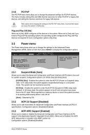
...] [Max.=2000] Memory Over Voltage [Auto] Manually set memory voltage or set this item to [Enabled] for shader. Configuration options: [Auto] [Min.=1.21000V] [Max.=2.47000V] ASUS AT3IONT-I Series 2-7 Configuration options: [Disabled] [Enabled] CPU TM function [Enabled] Enables or disables Intel® CPU Thermal Monitor (TM) function, a CPU overheating protection function. Configuration options...
...] [Max.=2000] Memory Over Voltage [Auto] Manually set memory voltage or set this item to [Enabled] for shader. Configuration options: [Auto] [Min.=1.21000V] [Max.=2.47000V] ASUS AT3IONT-I Series 2-7 Configuration options: [Disabled] [Enabled] CPU TM function [Enabled] Enables or disables Intel® CPU Thermal Monitor (TM) function, a CPU overheating protection function. Configuration options...
AT3IONT-I Series user's manual
Page 39
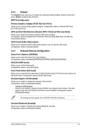
... enable or disable the onboard Bluetooth controller. Onboard Bluetooth [Enabled] Allows you to Enabled. Configuration options: [Enabled] [Disabled] ASUS AT3IONT-I DELUXE motherboard. Select an item then press to select the Serial Port1 base address. Configuration options: [Auto] [Disabled] ...Audio] Allows you to select the front panel type. Configuration options: [Disabled] [Enabled] The following two items appear only on AT3IONT-I Series 2-9 MCP7A Configuration Primary Graphics Adapter [PCIE VGA Card First] Allows you to set HD Audio mode. Configuration options: [Disabled...
... enable or disable the onboard Bluetooth controller. Onboard Bluetooth [Enabled] Allows you to Enabled. Configuration options: [Enabled] [Disabled] ASUS AT3IONT-I DELUXE motherboard. Select an item then press to select the Serial Port1 base address. Configuration options: [Auto] [Disabled] ...Audio] Allows you to select the front panel type. Configuration options: [Disabled] [Enabled] The following two items appear only on AT3IONT-I Series 2-9 MCP7A Configuration Primary Graphics Adapter [PCIE VGA Card First] Allows you to set HD Audio mode. Configuration options: [Disabled...
AT3IONT-I Series user's manual
Page 41
... than in the Application-Specific Integrated Circuit (ASIC). In S1 sleep state, the system appears suspended and stays in the system. Configuration options: [Disabled] [Enabled] ASUS AT3IONT-I Series 2-11 Configuration options: [S1 (POS) Only] [S3 Only] [Auto] [S1(POS) Only] - Enables the system to enter the ACPI S3 (Suspend to malfunction. In...
... than in the Application-Specific Integrated Circuit (ASIC). In S1 sleep state, the system appears suspended and stays in the system. Configuration options: [Disabled] [Enabled] ASUS AT3IONT-I Series 2-11 Configuration options: [S1 (POS) Only] [S3 Only] [Auto] [S1(POS) Only] - Enables the system to enter the ACPI S3 (Suspend to malfunction. In...
AT3IONT-I Series user's manual
Page 43
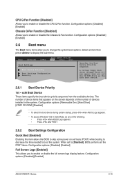
...disable the Chassis Q-Fan function. The number of device items that appears on the screen depends on the number of the following: • Press when ASUS Logo appears. • Press after POST. 2.6.2 Boot Settings Configuration Quick Boot [Enabled] Enabling this item allows the BIOS to skip some power on self... the system. Configuration options: [Disabled] [Enabled] Chassis Q-Fan Function [Disabled] Allows you to enable or disable the CPU Q-Fan function. Configuration options: [Disabled] [Enabled] ASUS AT3IONT-I Series 2-13 Select an item then press to boot the system.
...disable the Chassis Q-Fan function. The number of device items that appears on the screen depends on the number of the following: • Press when ASUS Logo appears. • Press after POST. 2.6.2 Boot Settings Configuration Quick Boot [Enabled] Enabling this item allows the BIOS to skip some power on self... the system. Configuration options: [Disabled] [Enabled] Chassis Q-Fan Function [Disabled] Allows you to enable or disable the CPU Q-Fan function. Configuration options: [Disabled] [Enabled] ASUS AT3IONT-I Series 2-13 Select an item then press to boot the system.
AT3IONT-I Series user's manual
Page 45
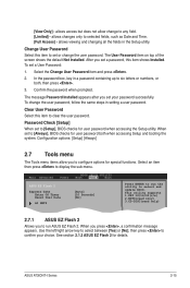
... Setup utility. Password Check [Setup] When set to six letters or numbers, or both when accessing Setup and booting the system. ASUS AT3IONT-I Series 2-15 The User Password item on top of the screen shows the default Not Installed. The message Password Installed appears after...Access] - After you press , a confirmation message appears. When set to set your choice. Main Advanced Power BIOS SETUP UTILITY Boot Tools Exit ASUS EZ Flash 2 Express Gate Enter OS Timer Reset User Data AI NET2 [Auto] [10 Seconds] [No] Press ENTER to confirm your password ...
... Setup utility. Password Check [Setup] When set to six letters or numbers, or both when accessing Setup and booting the system. ASUS AT3IONT-I Series 2-15 The User Password item on top of the screen shows the default Not Installed. The message Password Installed appears after...Access] - After you press , a confirmation message appears. When set to set your choice. Main Advanced Power BIOS SETUP UTILITY Boot Tools Exit ASUS EZ Flash 2 Express Gate Enter OS Timer Reset User Data AI NET2 [Auto] [10 Seconds] [No] Press ENTER to confirm your password ...


