AT3IONT-I Series user's manual
Page 3
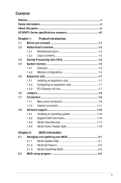
... this guide vi AT3IONT-I Series specifications summary viii Chapter 1: Product introduction 1.1 Before you proceed 1-1 1.2 Motherboard overview 1-2 1.2.1 Motherboard layout 1-2 1.2.2 Layout contents 1-2 1.3 Central Processing Unit (CPU 1-3 1.4 System memory 1-3 1.4.1 Overview 1-3 1.4.2 Memory configurations 1-4 1.5... Support DVD information 1-16 1.8.3 ASUS VideoSecurity 1-17 1.8.4 ASUS Home Theater Gate 1-19 Chapter 2: BIOS information 2.1 Managing and updating your BIOS 2-1 2.1.1 ASUS Update utility 2-1 2.1.2 ASUS EZ Flash 2 2-2 2.1.3 ASUS CrashFree BIOS 2-3 2.2 BIOS setup program...
... this guide vi AT3IONT-I Series specifications summary viii Chapter 1: Product introduction 1.1 Before you proceed 1-1 1.2 Motherboard overview 1-2 1.2.1 Motherboard layout 1-2 1.2.2 Layout contents 1-2 1.3 Central Processing Unit (CPU 1-3 1.4 System memory 1-3 1.4.1 Overview 1-3 1.4.2 Memory configurations 1-4 1.5... Support DVD information 1-16 1.8.3 ASUS VideoSecurity 1-17 1.8.4 ASUS Home Theater Gate 1-19 Chapter 2: BIOS information 2.1 Managing and updating your BIOS 2-1 2.1.1 ASUS Update utility 2-1 2.1.2 ASUS EZ Flash 2 2-2 2.1.3 ASUS CrashFree BIOS 2-3 2.2 BIOS setup program...
AT3IONT-I Series user's manual
Page 8
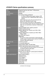
... mid-board, 6 ports at back panel) ASUS CrashFree BIOS 3 ASUS EZ Flash 2 ASUS MyLogo 2™ ASUS AI NET 2 ASUS Express Gate Home Theater Gate ASUS Q-Fan Stack Cool3+ (continued on the next page) viii AT3IONT-I Series specifications summary CPU Chipset Front Side Bus Memory Graphics Expansion slot Storage Audio LAN USB ASUS special features Integrated Dual-Core Intel®...
... mid-board, 6 ports at back panel) ASUS CrashFree BIOS 3 ASUS EZ Flash 2 ASUS MyLogo 2™ ASUS AI NET 2 ASUS Express Gate Home Theater Gate ASUS Q-Fan Stack Cool3+ (continued on the next page) viii AT3IONT-I Series specifications summary CPU Chipset Front Side Bus Memory Graphics Expansion slot Storage Audio LAN USB ASUS special features Integrated Dual-Core Intel®...
AT3IONT-I Series user's manual
Page 12
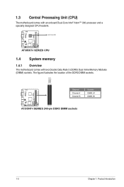
The figure illustrates the location of the DDR3 DIMM sockets: AT3IONT-I DELUXE DIMM_B1 DIMM_A1 Channel Channel A Channel B Sockets DIMM_A1 DIMM_B1 AT3IONT-I SERIES 240-pin DDR3 DIMM sockets 1-3 Chapter 1: Product introduction Intel® Atom330 AT3IONT-I SERIES CPU 1.4 System memory 1.4.1 Overview The motherboard comes with an onboard Dual-Core Intel® Atom™ 330 processor and a specially designed CPU heatsink. AT3IONT-I DELUXE 1.3 Central Processing Unit (CPU) The motherboard comes with two Double Data Rate 3 (DDR3) Dual Inline Memory Modules (DIMM) sockets.
The figure illustrates the location of the DDR3 DIMM sockets: AT3IONT-I DELUXE DIMM_B1 DIMM_A1 Channel Channel A Channel B Sockets DIMM_A1 DIMM_B1 AT3IONT-I SERIES 240-pin DDR3 DIMM sockets 1-3 Chapter 1: Product introduction Intel® Atom330 AT3IONT-I SERIES CPU 1.4 System memory 1.4.1 Overview The motherboard comes with an onboard Dual-Core Intel® Atom™ 330 processor and a specially designed CPU heatsink. AT3IONT-I DELUXE 1.3 Central Processing Unit (CPU) The motherboard comes with two Double Data Rate 3 (DDR3) Dual Inline Memory Modules (DIMM) sockets.
AT3IONT-I Series user's manual
Page 13
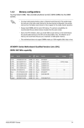
... that you install 4GB or more memory on the motherboard, the actual usable memory for the dual-channel configuration. AT3IONT-I Series 1-4 Voltage DIMM support A* B* - •• 1.35V(low voltage) • • - •• - •• - •• 1.5V •• - •• - •• - •• - •• ASUS AT3IONT-I Series Motherboard Qualified Vendors Lists...
... that you install 4GB or more memory on the motherboard, the actual usable memory for the dual-channel configuration. AT3IONT-I Series 1-4 Voltage DIMM support A* B* - •• 1.35V(low voltage) • • - •• - •• - •• 1.5V •• - •• - •• - •• - •• ASUS AT3IONT-I Series Motherboard Qualified Vendors Lists...
AT3IONT-I Series user's manual
Page 15
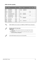
...-15 - SS: Single-sided / DS: Double-sided DIMM support: • A*: Supports one module inserted into either slot as the single-channel memory configuration. • B*: Supports one pair of modules inserted into both the blue slots as one pair of dual-channel...Patriot DS - Voltage - DDR3-1333 MHz capability Vendor Part No. DIMM support A* B - - •• 9 - •• - - •• - - •• DDR3 1333MHz memory modules run at www.asus.com for the latest QVL. ASUS AT3IONT-I Series motherboards. Visit the ASUS website at 1066MHz on...
...-15 - SS: Single-sided / DS: Double-sided DIMM support: • A*: Supports one module inserted into either slot as the single-channel memory configuration. • B*: Supports one pair of modules inserted into both the blue slots as one pair of dual-channel...Patriot DS - Voltage - DDR3-1333 MHz capability Vendor Part No. DIMM support A* B - - •• 9 - •• - - •• - - •• DDR3 1333MHz memory modules run at www.asus.com for the latest QVL. ASUS AT3IONT-I Series motherboards. Visit the ASUS website at 1066MHz on...

AT3IONT-I Series user's manual
Page 17
...memory of date, time, and system setup parameters by erasing the CMOS RTC RAM data. Move the jumper cap from pins 1-2 (default) to re-enter data. After clearing the CMOS, reinstall the battery. 1.7 Connectors 1.7.1 Rear panel connectors 1 2 3 4 5 6 78 16 15 14 13 12 11 10 9 ASUS AT3IONT...-I SERIES Clear RTC RAM To erase the RTC RAM: 1. AT3IONT-I DELUXE 12 23 CLRTC Normal (Default) Clear RTC AT3IONT-I Series 1-8 The onboard button cell battery powers the RAM data in CMOS. Except when ...
...memory of date, time, and system setup parameters by erasing the CMOS RTC RAM data. Move the jumper cap from pins 1-2 (default) to re-enter data. After clearing the CMOS, reinstall the battery. 1.7 Connectors 1.7.1 Rear panel connectors 1 2 3 4 5 6 78 16 15 14 13 12 11 10 9 ASUS AT3IONT...-I SERIES Clear RTC RAM To erase the RTC RAM: 1. AT3IONT-I DELUXE 12 23 CLRTC Normal (Default) Clear RTC AT3IONT-I Series 1-8 The onboard button cell battery powers the RAM data in CMOS. Except when ...
AT3IONT-I Series user's manual
Page 36
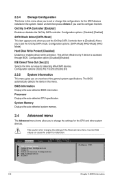
...] [RAID Mode] [AHCI Mode] Hard Disk Write Protect [Disabled] Disables or enables device write protection. Allows you to configure the item. System Memory Displays the auto-detected system memory. 2.4 Advanced menu The Advanced menu items allow you to set the OnChip SATA Controller item to malfunction. OnChip S-ATA Controller [Enabled] Enables or...
...] [RAID Mode] [AHCI Mode] Hard Disk Write Protect [Disabled] Disables or enables device write protection. Allows you to configure the item. System Memory Displays the auto-detected system memory. 2.4 Advanced menu The Advanced menu items allow you to set the OnChip SATA Controller item to malfunction. OnChip S-ATA Controller [Enabled] Enables or...
AT3IONT-I Series user's manual
Page 37
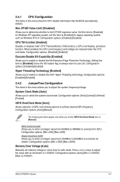
... System Clock Mode [Auto] Allows you to [Manual]. Configuration options: [Min.=1200] [Max.=2000] Memory Over Voltage [Auto] Manually set memory voltage or set the iGPU OverClock Mode item to enable or disable the No-Execution Page Protection Technology.... set this item to adjust the system frequency/voltage. When enabled, the CPU core frequency and voltage are reduced when the CPU overheats. Configuration options: [Auto] [Min.=1.21000V] [Max.=2.47000V] ASUS AT3IONT...
... System Clock Mode [Auto] Allows you to [Manual]. Configuration options: [Min.=1200] [Max.=2000] Memory Over Voltage [Auto] Manually set memory voltage or set the iGPU OverClock Mode item to enable or disable the No-Execution Page Protection Technology.... set this item to adjust the system frequency/voltage. When enabled, the CPU core frequency and voltage are reduced when the CPU overheats. Configuration options: [Auto] [Min.=1.21000V] [Max.=2.47000V] ASUS AT3IONT...

AT3IONT-I Series user's manual
Page 38
.... Configuration options: [Auto] [Manual] The following items appear only when you set the Memory Timings item to adjust the value with an increment of 0.05000V. Press / keys to [Manual]. Press / keys to Auto for safe mode. tCL (CAS Latency) [...
.... Configuration options: [Auto] [Manual] The following items appear only when you set the Memory Timings item to adjust the value with an increment of 0.05000V. Press / keys to [Manual]. Press / keys to Auto for safe mode. tCL (CAS Latency) [...
AT3IONT-I Series user's manual
Page 41
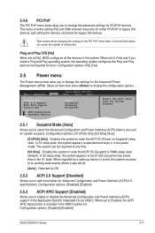
... to display the configuration options. The menu includes setting IRQ and DMA channel resources for either PCI/PnP or legacy ISA devices, and setting the memory size block for legacy ISA devices. When set to [Yes] and if you install a Plug and Play operating system, the operating system configures the Plug... Power Management (APM). 2.4.6 PCI PnP The PCI PnP menu items allow you to change the advanced settings for PCI/PnP devices. Configuration options: [Disabled] [Enabled] ASUS AT3IONT-I Series 2-11
... to display the configuration options. The menu includes setting IRQ and DMA channel resources for either PCI/PnP or legacy ISA devices, and setting the memory size block for legacy ISA devices. When set to [Yes] and if you install a Plug and Play operating system, the operating system configures the Plug... Power Management (APM). 2.4.6 PCI PnP The PCI PnP menu items allow you to change the advanced settings for PCI/PnP devices. Configuration options: [Disabled] [Enabled] ASUS AT3IONT-I Series 2-11


