
User Manual
Page 51
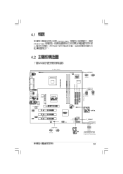
... / USBPW12 USBPW34 2 1 +5V (Default) 3 2 +5VSB ATX VIA VT6103 AUX1 CD1 AD1888 FP_AUDIO1 SPDIF AGP PCI PCI SB_PWR1 PCI CHA_FAN1 USBPW56 USBPW56 12 23 +5V (Default) +5VSB CR2032 CMOS 3 SiS 963L CLRTC P4S800-MX Clear RTC RAM CLRTC1 12 23 Normal (Default) Clear CMOS USB56 SPEAKER1 PLED1 F_PANEL1 GAME1 F_PANEL1 ATX Power Power LED Switch* PLED+ PLEDPWR GND IDE_LED+ IDE_LED- IDE_LED Reset SW * Requires an ATX power supply. 51
... / USBPW12 USBPW34 2 1 +5V (Default) 3 2 +5VSB ATX VIA VT6103 AUX1 CD1 AD1888 FP_AUDIO1 SPDIF AGP PCI PCI SB_PWR1 PCI CHA_FAN1 USBPW56 USBPW56 12 23 +5V (Default) +5VSB CR2032 CMOS 3 SiS 963L CLRTC P4S800-MX Clear RTC RAM CLRTC1 12 23 Normal (Default) Clear CMOS USB56 SPEAKER1 PLED1 F_PANEL1 GAME1 F_PANEL1 ATX Power Power LED Switch* PLED+ PLEDPWR GND IDE_LED+ IDE_LED- IDE_LED Reset SW * Requires an ATX power supply. 51

User Manual
Page 62
Ground Reset IDE_LED Reset SW * Requires an ATX power supply. P4S800-MX Front Panel Audio Connector • 3-1 pin PLED • ATX / BIOS 2-pin 3-pin 2-pin 3-pin 2-pin PWR_BTN • IDE • 2-pin IDE_LED IDE_LED IDE IDE 2-pin RESET Reset 62 12. 20-pin F_PANEL1 P4S800-MX PLED+ PLEDPWR GND ATX Power Power LED Switch* F_PANEL1 IDE_LED+ IDE_LED-
Ground Reset IDE_LED Reset SW * Requires an ATX power supply. P4S800-MX Front Panel Audio Connector • 3-1 pin PLED • ATX / BIOS 2-pin 3-pin 2-pin 3-pin 2-pin PWR_BTN • IDE • 2-pin IDE_LED IDE_LED IDE IDE 2-pin RESET Reset 62 12. 20-pin F_PANEL1 P4S800-MX PLED+ PLEDPWR GND ATX Power Power LED Switch* F_PANEL1 IDE_LED+ IDE_LED-
User Manual
Page 65
ASUS AFLASH DOS 3. http://www.asus.com BIOS 5.1.1 1. ASUS Update Windows BIOS 1. DOS 1.44MB 2. BIOS BIOS AFLASH BIOS 2. Windows b. / c. d. DOS format A:/S 1.44MB Windows a. 5.1 BIOS System 1. BIOS 65 ASUS EZ Flash Test POST BIOS 2. ASUS CrashFree BIOS BIOS BIOS Basic Input/Output Power-On Self BIOS BIOS 4.
ASUS AFLASH DOS 3. http://www.asus.com BIOS 5.1.1 1. ASUS Update Windows BIOS 1. DOS 1.44MB 2. BIOS BIOS AFLASH BIOS 2. Windows b. / c. d. DOS format A:/S 1.44MB Windows a. 5.1 BIOS System 1. BIOS 65 ASUS EZ Flash Test POST BIOS 2. ASUS CrashFree BIOS BIOS BIOS Basic Input/Output Power-On Self BIOS BIOS 4.

User Manual
Page 68
... flash .... done Writing flash .... 0x0008CC00 (9%) Verifying flash .. Starting BIOS recovery... Checking for floppy... • Floppy not found • BIOS P4S800MX.BIN not found BIOS P4S800MX.BIN 68 BIOS All rights reserved. Version 1.10 Copyright (C) 2002 American Megatrends, Inc. done A:\> 5.1.4 EZ Flash Test POST EZ Flash BIOS BIOS DOS + EZ Flash Power-On EZ Flash BIOS Self EZ Flash BIOS 1. POST EZ Flash BIOS + User recovery requested. www.asus.com P4S800MX.BIN 2. 3. A:\>afudos /iP4s800-MX.rom AMI Firmware Update Utility...
... flash .... done Writing flash .... 0x0008CC00 (9%) Verifying flash .. Starting BIOS recovery... Checking for floppy... • Floppy not found • BIOS P4S800MX.BIN not found BIOS P4S800MX.BIN 68 BIOS All rights reserved. Version 1.10 Copyright (C) 2002 American Megatrends, Inc. done A:\> 5.1.4 EZ Flash Test POST EZ Flash BIOS BIOS DOS + EZ Flash Power-On EZ Flash BIOS Self EZ Flash BIOS 1. POST EZ Flash BIOS + User recovery requested. www.asus.com P4S800MX.BIN 2. 3. A:\>afudos /iP4s800-MX.rom AMI Firmware Update Utility...

User Manual
Page 69
Start flashing... BIOS EZ Flash BIOS BIOS User recovery requested. Floppy found! Completed. Rebooting. 69 Checking for floppy... Flashed successfully. Reading file "p4s800-mx.bin". Starting BIOS recovery... 4.
Start flashing... BIOS EZ Flash BIOS BIOS User recovery requested. Floppy found! Completed. Rebooting. 69 Checking for floppy... Flashed successfully. Reading file "p4s800-mx.bin". Starting BIOS recovery... 4.

User Manual
Page 71
Use [+] or [-] to select a field. 5.2.1 BIOS System Time System Date Legacy Diskette A Primary IDE Master Primary IDE Slave Seconday IDE Master Secondary IDE Slave System Information [17:08:35] [Mon 04/19/2004] [1.44M, 3.5 in.] [ST320410A] [Pioneer CD-ROM ATA] [Not Detected] [Not Detected] Use [ENTER], [TAB] or [SHIFT-TAB] to configure system time. BIOS Main Advanced Power Boot Exit BIOS 71
Use [+] or [-] to select a field. 5.2.1 BIOS System Time System Date Legacy Diskette A Primary IDE Master Primary IDE Slave Seconday IDE Master Secondary IDE Slave System Information [17:08:35] [Mon 04/19/2004] [1.44M, 3.5 in.] [ST320410A] [Pioneer CD-ROM ATA] [Not Detected] [Not Detected] Use [ENTER], [TAB] or [SHIFT-TAB] to configure system time. BIOS Main Advanced Power Boot Exit BIOS 71

User Manual
Page 72
System Time System Date Legacy Diskette A [17:08:35] [Mon 04/19/2004] [1.44M, 3.5 in.] Primary IDE Master [ST320410A] Primary IDE Slave [Pioneer CD-ROM ATA] Seconday IDE Master [Not Detected] Secondary IDE Slave [Not Detected] System Information Use [ENTER], [TAB] or [SHIFT-TAB] to configure System Time. Enter Enter Primary Graphics Adapter [AGP] Search for MDA Resources [Yes] AGP Mode AGP Fast Write Graphics Aperture Size [AGP 8X] [Enabled] [64MB] Options Enabled Disabled PageUp PageDown 72 BIOS Use [+] or [-] to select a field.
System Time System Date Legacy Diskette A [17:08:35] [Mon 04/19/2004] [1.44M, 3.5 in.] Primary IDE Master [ST320410A] Primary IDE Slave [Pioneer CD-ROM ATA] Seconday IDE Master [Not Detected] Secondary IDE Slave [Not Detected] System Information Use [ENTER], [TAB] or [SHIFT-TAB] to configure System Time. Enter Enter Primary Graphics Adapter [AGP] Search for MDA Resources [Yes] AGP Mode AGP Fast Write Graphics Aperture Size [AGP 8X] [Enabled] [64MB] Options Enabled Disabled PageUp PageDown 72 BIOS Use [+] or [-] to select a field.
User Manual
Page 74
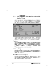
... IDE Master/Slave BIOS ATA IDE Enter IDE ATA Primary IDE Master Device : Hard Disk Vendor : ST320410A Size : 20.0GB LBA Mode : Supported Block Mode : 16 Sectors PIO Mode : 4 Async DMA : MultiWord DMA-2 Ultra DMA : Ultra DMA-5 SMART Monitoring: Supported Type LBA/Large Mode Block (Multi-Sector Transfer) PIO Mode SMART Monitoring 32Bit Data Transfer [Auto] [Auto] [Auto] [Auto] [Auto] [Disabled] Select the type of device connected to the...
... IDE Master/Slave BIOS ATA IDE Enter IDE ATA Primary IDE Master Device : Hard Disk Vendor : ST320410A Size : 20.0GB LBA Mode : Supported Block Mode : 16 Sectors PIO Mode : 4 Async DMA : MultiWord DMA-2 Ultra DMA : Ultra DMA-5 SMART Monitoring: Supported Type LBA/Large Mode Block (Multi-Sector Transfer) PIO Mode SMART Monitoring 32Bit Data Transfer [Auto] [Auto] [Auto] [Auto] [Auto] [Disabled] Select the type of device connected to the...
User Manual
Page 77
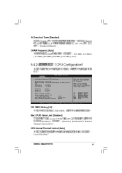
... MHz] [533 MHz] [Auto] 5.4.2 CPU Configuration Configure Advanced CPU settings Manufacturer: Intel(R) Brand String: Intel(R) Pentium(R) 4 Family CPU 2. 40G Frequency : 2400Mhz FSB Speed : 533Mhz Cache L1 Cache L2 Cache L3 : 8 KB : 512 KB : 0 KB Rario Status: Locked Ratio Actual Value: 18 VID CMOS Setting: Max CPUID Value Limit: CPU Internal Thermal Control [ 62] [Disabled] [Auto] Sets the ration between CPU Core Clock and the FSB...
... MHz] [533 MHz] [Auto] 5.4.2 CPU Configuration Configure Advanced CPU settings Manufacturer: Intel(R) Brand String: Intel(R) Pentium(R) 4 Family CPU 2. 40G Frequency : 2400Mhz FSB Speed : 533Mhz Cache L1 Cache L2 Cache L3 : 8 KB : 512 KB : 0 KB Rario Status: Locked Ratio Actual Value: 18 VID CMOS Setting: Max CPUID Value Limit: CPU Internal Thermal Control [ 62] [Disabled] [Auto] Sets the ration between CPU Core Clock and the FSB...

User Manual
Page 78
5.4.3 Enter Chipset Northbridge SiS661FX Configuration Southbridge SiS963/SiS963L Configuration Options for NB. SiS661FX NorthBridget Primary Graphics Adapter MA 1T/2T Select DRAM CAS# Latency DRAM Precharge Delay DRAM RAS# to CAS# Delay DRAM RAS# Precharge Graphic Win Size Share Memory Size [PCI] [Auto] [By SPD] [Auto] [Auto] [Auto] [ 64MB] [ 32MB] Select which graphics controller to use as the primary boot device. 78 BIOS
5.4.3 Enter Chipset Northbridge SiS661FX Configuration Southbridge SiS963/SiS963L Configuration Options for NB. SiS661FX NorthBridget Primary Graphics Adapter MA 1T/2T Select DRAM CAS# Latency DRAM Precharge Delay DRAM RAS# to CAS# Delay DRAM RAS# Precharge Graphic Win Size Share Memory Size [PCI] [Auto] [By SPD] [Auto] [Auto] [Auto] [ 64MB] [ 32MB] Select which graphics controller to use as the primary boot device. 78 BIOS

User Manual
Page 81
.../IRQ3] Serial Port2 Address [2F8/IRQ3] COM 1 COM 1 COM 2 [Disabled] [2F8/IRQ3] [3E8/IRQ4] [2E8/IRQ3] Parallel Port Address [Disabled] [3BC][Disabled] [378] [278] Onboard Game Port [Disabled] [Disabled] [Enables] Onboard MIDI Port [Disabled] [Disabled] [300] [330] MIDI 81 5.4.4 OnBoard Devices Configuration Configure Win697 Super IO Chipset Serial Port1 Address Serial Port2 Address Parallel Port Address Onboard Game Port Onboard MIDI Port [3F8/IRQ4] [2F8/IRQ3] [Disabled] [Disabled] [Disabled] Allows BIOS to select Serial Port1...
.../IRQ3] Serial Port2 Address [2F8/IRQ3] COM 1 COM 1 COM 2 [Disabled] [2F8/IRQ3] [3E8/IRQ4] [2E8/IRQ3] Parallel Port Address [Disabled] [3BC][Disabled] [378] [278] Onboard Game Port [Disabled] [Disabled] [Enables] Onboard MIDI Port [Disabled] [Disabled] [300] [330] MIDI 81 5.4.4 OnBoard Devices Configuration Configure Win697 Super IO Chipset Serial Port1 Address Serial Port2 Address Parallel Port Address Onboard Game Port Onboard MIDI Port [3F8/IRQ4] [2F8/IRQ3] [Disabled] [Disabled] [Disabled] Allows BIOS to select Serial Port1...
User Manual
Page 82
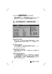
... [Disabled] VGA [Disabled] [Enabled] MPEG [Enabled] [Disabled] 82 BIOS YES: Lets the operating system configure Plug and Play (PnP) devices not required for boot if your system has a Plug and Play operating system. Plug and Play O/S [No] [No] BIOS [Yes] [Yes] [No] PCI Latency Timer [64] PCI [96] [128] [160] [192] [224] [248] [32] [64] Allocate IRQ to malfunction. 5.4.5 PCI PCI/PnP IRQ DMA PCI PnP PCI/PnP Advanced PCI/PnP settings WARNING: Setting wrong...
... [Disabled] VGA [Disabled] [Enabled] MPEG [Enabled] [Disabled] 82 BIOS YES: Lets the operating system configure Plug and Play (PnP) devices not required for boot if your system has a Plug and Play operating system. Plug and Play O/S [No] [No] BIOS [Yes] [Yes] [No] PCI Latency Timer [64] PCI [96] [128] [160] [192] [224] [248] [32] [64] Allocate IRQ to malfunction. 5.4.5 PCI PCI/PnP IRQ DMA PCI PnP PCI/PnP Advanced PCI/PnP settings WARNING: Setting wrong...
User Manual
Page 85
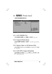
5.5 Power menu ACPI Aware O/S Suspend Mode Repost Video on S3 Resume ACPI APIC Support APM Configuration Hardware Monitor [Yes] [Auto] [No] [Enabled] Select the ACPI state used for System Suspend. 5.5.1 ACPI AWARE O/S ACPI [Yes] [No] 5.5.2 Suspend Mode [Auto] [Auto] [S1 (POS) only] [S3 Only] 5.5.3 Repost Video on S3 Resume [No] [No] [Yes] S3/STR VGA BIOS POST 5.5.4 ACPI APIC Support [Enabled] ACPI APIC [Enabled] [Disabled] RSDT 85
5.5 Power menu ACPI Aware O/S Suspend Mode Repost Video on S3 Resume ACPI APIC Support APM Configuration Hardware Monitor [Yes] [Auto] [No] [Enabled] Select the ACPI state used for System Suspend. 5.5.1 ACPI AWARE O/S ACPI [Yes] [No] 5.5.2 Suspend Mode [Auto] [Auto] [S1 (POS) only] [S3 Only] 5.5.3 Repost Video on S3 Resume [No] [No] [Yes] S3/STR VGA BIOS POST 5.5.4 ACPI APIC Support [Enabled] ACPI APIC [Enabled] [Disabled] RSDT 85

User Manual
Page 86
...By Internal MAC LAN Power On By PCI Devices Power On By External Modems Power On By RTC Alarm APM Configuration APM [Always OFF] [Disabled] [Disabled] [Disabled] [Disabled] [Disabled] [Disabled] Go into On/Off, or Suspend when Power button is pressed. Restore on AC Power Loss [Power Off] [Power Off] On] [Power On] Power On with PS/2 Keyboard [Disabled] [Enabled] PS2 ATX 1 [Disabled] [Enabled] Power On with PS/2 Mouse [Disabled] [Enabled] PS2 ATX 1 [Disabled] [Enabled] Power On By Internal MAC LAN [Disabled] [Enabled] MAC [Power [Power Off] 5VSB 5VSB [Disabled] 86 BIOS
...By Internal MAC LAN Power On By PCI Devices Power On By External Modems Power On By RTC Alarm APM Configuration APM [Always OFF] [Disabled] [Disabled] [Disabled] [Disabled] [Disabled] [Disabled] Go into On/Off, or Suspend when Power button is pressed. Restore on AC Power Loss [Power Off] [Power Off] On] [Power On] Power On with PS/2 Keyboard [Disabled] [Enabled] PS2 ATX 1 [Disabled] [Enabled] Power On with PS/2 Mouse [Disabled] [Enabled] PS2 ATX 1 [Disabled] [Enabled] Power On By Internal MAC LAN [Disabled] [Enabled] MAC [Power [Power Off] 5VSB 5VSB [Disabled] 86 BIOS
User Manual
Page 88
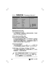
Enter Power setup menu for details Press F1 to continue or DEL to enter SETUP F1 DEL 88 BIOS MB Temperature [xxxC/xxxF] CPU Temperature [xxxC/xxxF] CPU Fan Speed [xxxxRPM] or [N/A] Chassis Fan Speed [xxxxRPM] or [N/A] RPM Rotations Per Minute Q-Fan Function [Enabled] ASUS Q-Fan ASUS Q-Fan [Disabled] [Enabled] VCORE Voltage, +3.3V Voltage, +5V Voltage, +12V Voltage CPU : Hardware Monitor found an error. 5.5.6 Hardware Monitor Hardware Monitor CPU Temperature MB Temperature CPU Fan Speed Chassis Fan Speed Q-Fan Control Q-Fan Control Temperature Q-Fan Control Tolerance VCORE ...
Enter Power setup menu for details Press F1 to continue or DEL to enter SETUP F1 DEL 88 BIOS MB Temperature [xxxC/xxxF] CPU Temperature [xxxC/xxxF] CPU Fan Speed [xxxxRPM] or [N/A] Chassis Fan Speed [xxxxRPM] or [N/A] RPM Rotations Per Minute Q-Fan Function [Enabled] ASUS Q-Fan ASUS Q-Fan [Disabled] [Enabled] VCORE Voltage, +3.3V Voltage, +5V Voltage, +12V Voltage CPU : Hardware Monitor found an error. 5.5.6 Hardware Monitor Hardware Monitor CPU Temperature MB Temperature CPU Fan Speed Chassis Fan Speed Q-Fan Control Q-Fan Control Temperature Q-Fan Control Tolerance VCORE ...
User Manual
Page 90
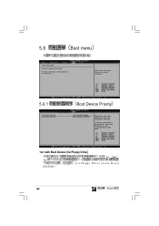
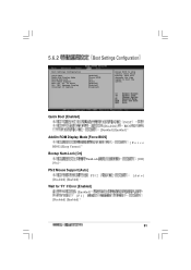
5.6 Boot menu Boot Settings Boot Device Priority Boot Settings Configuration Security Specifies the Boot Device Priority sequence. 5.6.1 Boot Device Priority 1st Boot Device 2nd Boot Device Boot Device Priority [1st FLOPPY DRIVE] [PS-Pioneer CD-ROM] Specifies the boot sequence from the available devices. A device enclosed in parenthesis has been disabled in the corresponding type menu. 1st~xxth Boot Device [1st Floopy Drive] 3rd [Disabled] 1st 2nd [1st Floppy Drive] [xxxxx Drive] 90 BIOS
5.6 Boot menu Boot Settings Boot Device Priority Boot Settings Configuration Security Specifies the Boot Device Priority sequence. 5.6.1 Boot Device Priority 1st Boot Device 2nd Boot Device Boot Device Priority [1st FLOPPY DRIVE] [PS-Pioneer CD-ROM] Specifies the boot sequence from the available devices. A device enclosed in parenthesis has been disabled in the corresponding type menu. 1st~xxth Boot Device [1st Floopy Drive] 3rd [Disabled] 1st 2nd [1st Floppy Drive] [xxxxx Drive] 90 BIOS
User Manual
Page 91
...] [Force Bootup Num-Lock [On] NumLock [Off] [On] PS/2 Mouse Support [Auto] [Disabled] [Enabled] PS/2 [Auto] Wait for 'F1' If Error Hit 'DEL' Message Display Interrupt 19 Capture [Enabled] [Force BIOS] [On] [Auto] [Enabled] [Enabled] [Disabled] Allows BIOS to boot the system. 5.6.2 Boot Settings Configuration Boot Settings Configuration Quick Boot AddOn ROM Display Mode Bootup Num-Lock PS/2 Mouse Support Wait for 'F1' If Error [Enabled] [Enabled] [F1] [Disabled] [Enabled] 91 This will decrease the time needed to skip certain tests while booting.
...] [Force Bootup Num-Lock [On] NumLock [Off] [On] PS/2 Mouse Support [Auto] [Disabled] [Enabled] PS/2 [Auto] Wait for 'F1' If Error Hit 'DEL' Message Display Interrupt 19 Capture [Enabled] [Force BIOS] [On] [Auto] [Enabled] [Enabled] [Disabled] Allows BIOS to boot the system. 5.6.2 Boot Settings Configuration Boot Settings Configuration Quick Boot AddOn ROM Display Mode Bootup Num-Lock PS/2 Mouse Support Wait for 'F1' If Error [Enabled] [Enabled] [F1] [Disabled] [Enabled] 91 This will decrease the time needed to skip certain tests while booting.
User Manual
Page 92
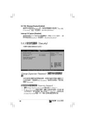
Hit 'DEL' Message Display [Enabled] to run Setup [Enabled] [Disabled] [Enabled] Press DEL Interrupt 19 Capture [Disabled] PCI [Enabled] SCSI [Disabled] [Enabled] 5.6.3 Security Security Settings Supervisor Password User Password Change Supervisor Password Change User Password Clear User Password Not Installed Not Installed to disable password. Change Supervisor Password [Installed] [Not Installed] Supervisor Password 1. [Change Supervisor Password] Enter 2. [Enter Password] [Confirm Password] Enter 92 BIOS again to change password.
Hit 'DEL' Message Display [Enabled] to run Setup [Enabled] [Disabled] [Enabled] Press DEL Interrupt 19 Capture [Disabled] PCI [Enabled] SCSI [Disabled] [Enabled] 5.6.3 Security Security Settings Supervisor Password User Password Change Supervisor Password Change User Password Clear User Password Not Installed Not Installed to disable password. Change Supervisor Password [Installed] [Not Installed] Supervisor Password 1. [Change Supervisor Password] Enter 2. [Enter Password] [Confirm Password] Enter 92 BIOS again to change password.
User Manual
Page 93
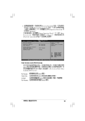
User Access Level [Full Access] BIOS BIOS [Limited] [Full Access] No Access View Only Limited Full Access BIOS BIOS BIOS BIOS [No Access] [View Only] 93 3. [Password Installed] [Password do not match!] [Supervisor Password] [Installed] [Change Supervisor Word] Password] Enter [Password uninstalled] [Enter Security Settings Supervisor Password User Password Change Supervisor Password User Access Level Change User Password Password Check Not Installed Not Installed [Full Access] [Setup] to disable password. again to change password.
User Access Level [Full Access] BIOS BIOS [Limited] [Full Access] No Access View Only Limited Full Access BIOS BIOS BIOS BIOS [No Access] [View Only] 93 3. [Password Installed] [Password do not match!] [Supervisor Password] [Installed] [Change Supervisor Word] Password] Enter [Password uninstalled] [Enter Security Settings Supervisor Password User Password Change Supervisor Password User Access Level Change User Password Password Check Not Installed Not Installed [Full Access] [Setup] to disable password. again to change password.
User Manual
Page 94
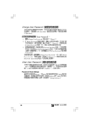
Change User Password [Installed] [Not Installed] User Password 1. [Change User Password] Enter 2. [Enter Password] [Confirm Password] Enter 3. [Password Installed] [Password do not match!] [User Password] [Installed] Password] [Password uninstalled] [Change User Password] Enter [Enter Clear User Password RTC 1.CMOS CLRTC1 CMOS 4.3 Password Check [Setup] [Setup] BIOS BIOS [Always] BIOS [Setup] [Always] 94 BIOS
Change User Password [Installed] [Not Installed] User Password 1. [Change User Password] Enter 2. [Enter Password] [Confirm Password] Enter 3. [Password Installed] [Password do not match!] [User Password] [Installed] Password] [Password uninstalled] [Change User Password] Enter [Enter Clear User Password RTC 1.CMOS CLRTC1 CMOS 4.3 Password Check [Setup] [Setup] BIOS BIOS [Always] BIOS [Setup] [Always] 94 BIOS


