
AP2300 Server in English
Page 4
... 21 4-4 Central Processing Unit (CPU 22 Installing S370 CPU 22 4-5 Fan Heatsink 23 Fan Heatsink Attachment 23 4 AP2300 Hardware Reference Guide Introduction 7 1-1 How this Manual is Organized 7 Symbols 7 1-2 Component Checklist 8 Standard components 8 Optional components 8 1-3 Features 9 Motherboard: ASUS CUR-DLS 9 Chassis: AS-30 9 1-4 Safeguards 10 Operation Safety 10 Tools Required 10 1-5 Electrical Safety 11...
... 21 4-4 Central Processing Unit (CPU 22 Installing S370 CPU 22 4-5 Fan Heatsink 23 Fan Heatsink Attachment 23 4 AP2300 Hardware Reference Guide Introduction 7 1-1 How this Manual is Organized 7 Symbols 7 1-2 Component Checklist 8 Standard components 8 Optional components 8 1-3 Features 9 Motherboard: ASUS CUR-DLS 9 Chassis: AS-30 9 1-4 Safeguards 10 Operation Safety 10 Tools Required 10 1-5 Electrical Safety 11...
AP2300 Server in English
Page 8
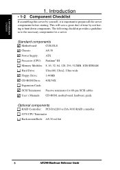
1. Standard components Motherboard: CUR-DLS Chassis: AS-30 Power Supply: ATX Processor (CPU): Pentium® III Memory Modules: 8, 16, 32, 64, 128, 256, 512MB, 1GB SDRAM Hard Drive: ... starting. Introduction • 1-2 Component Checklist If assembling this server by not having to the necessary components for 68-pin SCSI cables User's Manuals: CD-ROM, motherboard, hardware guide Optional components RAID Controller: PCI-DA2200 or DA-3000 RAID controller S370 CPU Terminator Rack-mount Rails: AS-30 rail kit...
1. Standard components Motherboard: CUR-DLS Chassis: AS-30 Power Supply: ATX Processor (CPU): Pentium® III Memory Modules: 8, 16, 32, 64, 128, 256, 512MB, 1GB SDRAM Hard Drive: ... starting. Introduction • 1-2 Component Checklist If assembling this server by not having to the necessary components for 68-pin SCSI cables User's Manuals: CD-ROM, motherboard, hardware guide Optional components RAID Controller: PCI-DA2200 or DA-3000 RAID controller S370 CPU Terminator Rack-mount Rails: AS-30 rail kit...
AP2300 Server in English
Page 9
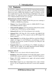
AP2300 Hardware Reference Guide 9 Motherboard: ASUS CUR-DLS • Processor: Dual Intel® Pentium III FC... following are highlights to accelerate even the most complicated server tasks. For additional features and details, read the motherboard User's Manual included with Ultra DMA/33 support, one floppy, two serial COM ports, one parallel port.... • Expansion Slots: Six or seven PCI slots (33 or 66MHz, depending on the ASUS CUR-DLS smart motherboard which uses the ServerSetTM chipset from ServerWorks®, supporting dual Pentium III processors and 133MHz Front Side...
AP2300 Hardware Reference Guide 9 Motherboard: ASUS CUR-DLS • Processor: Dual Intel® Pentium III FC... following are highlights to accelerate even the most complicated server tasks. For additional features and details, read the motherboard User's Manual included with Ultra DMA/33 support, one floppy, two serial COM ports, one parallel port.... • Expansion Slots: Six or seven PCI slots (33 or 66MHz, depending on the ASUS CUR-DLS smart motherboard which uses the ServerSetTM chipset from ServerWorks®, supporting dual Pentium III processors and 133MHz Front Side...

AP2300 Server in English
Page 11
... a properly grounded electrical outlet to prevent this damage. CAUTION This product is out of the system. • Grasp cards and boards by the frame. IMPORTANT Motherboards, adapters, and disk drives are wrapped in order to static electricity discharge. Hold drives by the edges...
... a properly grounded electrical outlet to prevent this damage. CAUTION This product is out of the system. • Grasp cards and boards by the frame. IMPORTANT Motherboards, adapters, and disk drives are wrapped in order to static electricity discharge. Hold drives by the edges...

AP2300 Server in English
Page 15
Components BBaacckk SSiiddee 2. Rear Fans Server Left Side AP2300 Hardware Reference Guide 15 Motherboard 3. System Overview • 2-3 Server Left Side 1 5 2 3 4 1. Chassis Intrusion Micro Switch 4. II. Power Supply 2. Overview Left Side 2. Chassis Stabilizer 5.
Components BBaacckk SSiiddee 2. Rear Fans Server Left Side AP2300 Hardware Reference Guide 15 Motherboard 3. System Overview • 2-3 Server Left Side 1 5 2 3 4 1. Chassis Intrusion Micro Switch 4. II. Power Supply 2. Overview Left Side 2. Chassis Stabilizer 5.
AP2300 Server in English
Page 16
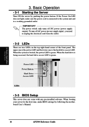
... one is the power LED and the lower one is green. Basic Operation • 3-1 Starting the Server Turn ON the server by following the motherboard User's Manual. 16 AP2300 Reference Guide IMPORTANT The power switch only turns off AC power (power supply input), you need to a working grounded outlet. When the system...
... one is the power LED and the lower one is green. Basic Operation • 3-1 Starting the Server Turn ON the server by following the motherboard User's Manual. 16 AP2300 Reference Guide IMPORTANT The power switch only turns off AC power (power supply input), you need to a working grounded outlet. When the system...
AP2300 Server in English
Page 20
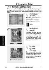
... necessary to provide the needed stabilization to support all the motherboard expansion cards used with the motherboard spacers are connected to overtighten the screws. The four screws used in this chassis. Hardware Setup Motherboard Placement 20 AP2300 Hardware Reference Guide 4. Be careful not to the motherboard's chassis intrusion connector through a single connector. 4. Doing so may...
... necessary to provide the needed stabilization to support all the motherboard expansion cards used with the motherboard spacers are connected to overtighten the screws. The four screws used in this chassis. Hardware Setup Motherboard Placement 20 AP2300 Hardware Reference Guide 4. Be careful not to the motherboard's chassis intrusion connector through a single connector. 4. Doing so may...

AP2300 Server in English
Page 21
... Cable Device Cables Several cables are properly secured. 4. Plastic keepers protect the cables from contacting with two 68-pin SCSI connectors. The motherboard includes onboard SCSI with the fans and other devices. The picture above points out the name of each cable and its suggested location. ...Hardware Setup Motherboard Placement Floppy Drive Cable IDE Cable 68-pin SCSI Cable 68-pin SCSI Cable Cable Connections The cables connect to the motherboard as shown. 4. Make sure that all cables are used for connecting ...
... Cable Device Cables Several cables are properly secured. 4. Plastic keepers protect the cables from contacting with two 68-pin SCSI connectors. The motherboard includes onboard SCSI with the fans and other devices. The picture above points out the name of each cable and its suggested location. ...Hardware Setup Motherboard Placement Floppy Drive Cable IDE Cable 68-pin SCSI Cable 68-pin SCSI Cable Cable Connections The cables connect to the motherboard as shown. 4. Make sure that all cables are used for connecting ...
AP2300 Server in English
Page 22
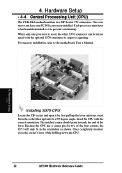
...the CPU with the optional S370 terminator to a 90-degree angle. Once completely inserted, close the socket's lever while holding down the CPU. 22 AP2300 Hardware Reference Guide 4. When only one FC-PGA processor installed. Each processor must have one processor is used, the other S370 connector can have a... the lever sideways away from the socket then upwards to improve signaling. Hardware Setup • 4-4 Central Processing Unit (CPU) The CUR-DLS motherboard has two ZIF Socket 370 connectors. Hardware Setup CPU Installing S370 CPU Locate the ZIF socket and open it to the...
...the CPU with the optional S370 terminator to a 90-degree angle. Once completely inserted, close the socket's lever while holding down the CPU. 22 AP2300 Hardware Reference Guide 4. When only one FC-PGA processor installed. Each processor must have one processor is used, the other S370 connector can have a... the lever sideways away from the socket then upwards to improve signaling. Hardware Setup • 4-4 Central Processing Unit (CPU) The CUR-DLS motherboard has two ZIF Socket 370 connectors. Hardware Setup CPU Installing S370 CPU Locate the ZIF socket and open it to the...

AP2300 Server in English
Page 23
Attach the heatsink clip over the mounted CPU. To remove the fan heatsink, reverse the installation procedure. 4. Hardware Setup Fan Heatsink AP2300 Hardware Reference Guide 23 Connect the fan power plug to the motherboard. CPU Fan Power Fan Heatsink Clip Fan Heatsink Attachment To install the fan heatsink, first align the fan heatsink over the clip attach point as shown above. Hardware Setup • 4-5 Fan Heatsink The CPU must have a fan heatsink that covers the face of the CPU. 4.
Attach the heatsink clip over the mounted CPU. To remove the fan heatsink, reverse the installation procedure. 4. Hardware Setup Fan Heatsink AP2300 Hardware Reference Guide 23 Connect the fan power plug to the motherboard. CPU Fan Power Fan Heatsink Clip Fan Heatsink Attachment To install the fan heatsink, first align the fan heatsink over the clip attach point as shown above. Hardware Setup • 4-5 Fan Heatsink The CPU must have a fan heatsink that covers the face of the CPU. 4.

AP2300 Server in English
Page 24
The motherboard will signal the ASMA software when the side panel is given here. 4. Hardware Setup • 4-6 Chassis Intrusion Switch The chassis provides a micro toggle switch that must be connected to the motherboard for the chassis intrusion detection to work. The connection diagram is opened. Hardware Setup Chassis Intrusion Switch Cable Chassis Intrusion Switches (one on each side) from the two Chassis Intrusion Switches Motherboard's Chassis Intrusion Lead (No Connection) GND Chasis Signal 24 AP2300 Hardware Reference Guide 4.
The motherboard will signal the ASMA software when the side panel is given here. 4. Hardware Setup • 4-6 Chassis Intrusion Switch The chassis provides a micro toggle switch that must be connected to the motherboard for the chassis intrusion detection to work. The connection diagram is opened. Hardware Setup Chassis Intrusion Switch Cable Chassis Intrusion Switches (one on each side) from the two Chassis Intrusion Switches Motherboard's Chassis Intrusion Lead (No Connection) GND Chasis Signal 24 AP2300 Hardware Reference Guide 4.

AP2300 Server in English
Page 34
... the SMB In connector on the DA-BP5E SCSI backplane board. SMBus Connector SMBDATA GND SMBCLK SMB In SMB Out CUR-DLS Motherboard DA-BP5E SCSI Backplane Board 34 AP2300 Hardware Reference Guide Hardware Setup SCSI Termination / SMB Female Terminator for SCSI cable Male Terminator for SCSI devices to work properly. Hardware...
... the SMB In connector on the DA-BP5E SCSI backplane board. SMBus Connector SMBDATA GND SMBCLK SMB In SMB Out CUR-DLS Motherboard DA-BP5E SCSI Backplane Board 34 AP2300 Hardware Reference Guide Hardware Setup SCSI Termination / SMB Female Terminator for SCSI cable Male Terminator for SCSI devices to work properly. Hardware...

AP2300 Server in English
Page 40
Hardware Setup Power Consumption 40 AP2300 Hardware Reference Guide Hardware Setup • 4-18 Power Supply Requirement Power Supply Requirement Calculation Table Item Volts Amp x Qty. = TotalAmp Total Watts Motherboard* 3.3V 5.0V 12.0V 54.78 147.40 4.00 Hard Drive 5.0V 12.0V x = x = CD-ROM 5.0V 12.0V x = x = Tape Drive 5.0V 12.0V...
Hardware Setup Power Consumption 40 AP2300 Hardware Reference Guide Hardware Setup • 4-18 Power Supply Requirement Power Supply Requirement Calculation Table Item Volts Amp x Qty. = TotalAmp Total Watts Motherboard* 3.3V 5.0V 12.0V 54.78 147.40 4.00 Hard Drive 5.0V 12.0V x = x = CD-ROM 5.0V 12.0V x = x = Tape Drive 5.0V 12.0V...
AP2300 Server in English
Page 41
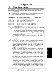
... quality of your cable and devices. • A total of 15 devices may be connected to the 68-pin Ultra2 connector on the motherboard. • If connecting Fast/Ultra devices with Ultra2 devices on the Ultra2 connector, the entire SCSI bus will depend on one time. ...Mixing SCSI devices is unstable over long lengths, therefore stability will be connected to the 50-pin Narrow connector. 5. Appendix SCSI Cable Limits AP2300 Hardware Reference Guide 41 Cable Limits Max Data Transfer Rates Max Devices 1) 12m (29.4ft) 2) 3m - 1.5m 3) 3m (9.8ft) 4) 3m - 1.5m ...
... quality of your cable and devices. • A total of 15 devices may be connected to the 68-pin Ultra2 connector on the motherboard. • If connecting Fast/Ultra devices with Ultra2 devices on the Ultra2 connector, the entire SCSI bus will depend on one time. ...Mixing SCSI devices is unstable over long lengths, therefore stability will be connected to the 50-pin Narrow connector. 5. Appendix SCSI Cable Limits AP2300 Hardware Reference Guide 41 Cable Limits Max Data Transfer Rates Max Devices 1) 12m (29.4ft) 2) 3m - 1.5m 3) 3m (9.8ft) 4) 3m - 1.5m ...

AP2300 Server in English
Page 43
... 16 Hard Drive Access 13 Power 13, 16 Left Panel 18 Lock 13 E ECC 9 EMI 37, 39 Expansion Cards 8, 25 Expansion Card Guide 15, 25 M Motherboard 8, 15 Placement 20 Spacers 20 AP2300 Hardware Reference Guide 43
... 16 Hard Drive Access 13 Power 13, 16 Left Panel 18 Lock 13 E ECC 9 EMI 37, 39 Expansion Cards 8, 25 Expansion Card Guide 15, 25 M Motherboard 8, 15 Placement 20 Spacers 20 AP2300 Hardware Reference Guide 43

