
AP2300 Server in English
Page 2
...00 E540 Release Date: June 2000 2 AP2300 Hardware Reference Guide Product warranty or service will not be extended if: (1) the product is repaired, modified or altered, unless such repair, modification of alteration is defaced or missing. IN NO EVENT SHALL ASUS, ITS DIRECTORS, OFFICERS, EMPLOYEES OR ...in this manual, including the products and software described in it, may not be registered trademarks or copyrights of ASUSTeK COMPUTER INC. ("ASUS"). ASUS PROVIDES THIS MANUAL "AS IS" WITHOUT WARRANTY OF ANY KIND, EITHER EXPRESS OR IMPLIED, INCLUDING BUT NOT LIMITED TO THE IMPLIED ...
...00 E540 Release Date: June 2000 2 AP2300 Hardware Reference Guide Product warranty or service will not be extended if: (1) the product is repaired, modified or altered, unless such repair, modification of alteration is defaced or missing. IN NO EVENT SHALL ASUS, ITS DIRECTORS, OFFICERS, EMPLOYEES OR ...in this manual, including the products and software described in it, may not be registered trademarks or copyrights of ASUSTeK COMPUTER INC. ("ASUS"). ASUS PROVIDES THIS MANUAL "AS IS" WITHOUT WARRANTY OF ANY KIND, EITHER EXPRESS OR IMPLIED, INCLUDING BUT NOT LIMITED TO THE IMPLIED ...
AP2300 Server in English
Page 3
...) Notebook (Tel): +886-2-2890-7122 (English) Desktop/Server (Tel):+886-2-2890-7123 (English) Fax: +886-2-2895-9254 Email: tsd@asus.com.tw WWW: www.asus.com.tw FTP: ftp.asus.com.tw/pub/ASUS ASUS COMPUTER INTERNATIONAL (America) Marketing Address: Fax: Email: 6737 Mowry Avenue, Mowry Business Center, Building 2 Newark, CA 94560, USA +1-510-608... Fax: +49-2102-9599-11 Support (Email): www.asuscom.de/de/support (for online support) WWW: www.asuscom.de FTP: ftp.asuscom.de/pub/ASUSCOM AP2300 Hardware Reference Guide 3
...) Notebook (Tel): +886-2-2890-7122 (English) Desktop/Server (Tel):+886-2-2890-7123 (English) Fax: +886-2-2895-9254 Email: tsd@asus.com.tw WWW: www.asus.com.tw FTP: ftp.asus.com.tw/pub/ASUS ASUS COMPUTER INTERNATIONAL (America) Marketing Address: Fax: Email: 6737 Mowry Avenue, Mowry Business Center, Building 2 Newark, CA 94560, USA +1-510-608... Fax: +49-2102-9599-11 Support (Email): www.asuscom.de/de/support (for online support) WWW: www.asuscom.de FTP: ftp.asuscom.de/pub/ASUSCOM AP2300 Hardware Reference Guide 3
AP2300 Server in English
Page 4
... Intrusion Connector 20 Device Cables 21 Cable Connections 21 4-4 Central Processing Unit (CPU 22 Installing S370 CPU 22 4-5 Fan Heatsink 23 Fan Heatsink Attachment 23 4 AP2300 Hardware Reference Guide System Overview 13 2-1 Server Front Side 13 2-2 Server Back Side 14 2-3 Server Left Side 15 3. Contents 1. Introduction 7 1-1 How this Manual is Organized...
... Intrusion Connector 20 Device Cables 21 Cable Connections 21 4-4 Central Processing Unit (CPU 22 Installing S370 CPU 22 4-5 Fan Heatsink 23 Fan Heatsink Attachment 23 4 AP2300 Hardware Reference Guide System Overview 13 2-1 Server Front Side 13 2-2 Server Back Side 14 2-3 Server Left Side 15 3. Contents 1. Introduction 7 1-1 How this Manual is Organized...

AP2300 Server in English
Page 5
... Power Supply Information 38 4-18 Power Supply Requirement 40 Power Supply Requirement Calculation Table 40 5. Appendix 41 5-1 SCSI Cable Limits 41 5-2 Glossary 42 Index 43 AP2300 Hardware Reference Guide 5
... Power Supply Information 38 4-18 Power Supply Requirement 40 Power Supply Requirement Calculation Table 40 5. Appendix 41 5-1 SCSI Cable Limits 41 5-2 Glossary 42 Index 43 AP2300 Hardware Reference Guide 5

AP2300 Server in English
Page 6
... or relocate the receiving antenna. • Increase the separation between the equipment and receiver. • Connect the equipment to radio communications. Canadian Department of Communications. 6 AP2300 Hardware Reference Guide This equipment generates, uses and can be determined by turning the equipment off and on a circuit different from digital apparatus set out...
... or relocate the receiving antenna. • Increase the separation between the equipment and receiver. • Connect the equipment to radio communications. Canadian Department of Communications. 6 AP2300 Hardware Reference Guide This equipment generates, uses and can be determined by turning the equipment off and on a circuit different from digital apparatus set out...
AP2300 Server in English
Page 7
... to prevent damage to the components when trying to complete a task. S1.e1I.ctInitonrtnrosod/ducSutycitiomonbnols 1. Introduction You are reading the AP2300 Hardware Reference Guide. STANDARD (FLAT) SCREW DRIVER: Tools required to complete a task. This hardware reference guide provides information and ... to install or remove the components in order to install or remove the components in completing a task. AP2300 Hardware Reference Guide 7 IMPORTANT: Information that MUST be individually purchased to help plan your separately purchased components. • 1-1 How...
... to prevent damage to the components when trying to complete a task. S1.e1I.ctInitonrtnrosod/ducSutycitiomonbnols 1. Introduction You are reading the AP2300 Hardware Reference Guide. STANDARD (FLAT) SCREW DRIVER: Tools required to complete a task. This hardware reference guide provides information and ... to install or remove the components in order to install or remove the components in completing a task. AP2300 Hardware Reference Guide 7 IMPORTANT: Information that MUST be individually purchased to help plan your separately purchased components. • 1-1 How...
AP2300 Server in English
Page 8
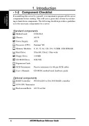
...-ROM, motherboard, hardware guide Optional components RAID Controller: PCI-DA2200 or DA-3000 RAID controller S370 CPU Terminator Rack-mount Rails: AS-30 rail kit 8 AP2300 Hardware Reference Guide 1. Introduction Checklist 1.
...-ROM, motherboard, hardware guide Optional components RAID Controller: PCI-DA2200 or DA-3000 RAID controller S370 CPU Terminator Rack-mount Rails: AS-30 rail kit 8 AP2300 Hardware Reference Guide 1. Introduction Checklist 1.
AP2300 Server in English
Page 9
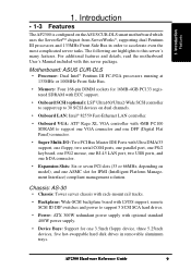
...which uses the ServerSetTM chipset from ServerWorks®, supporting dual Pentium III processors and 133MHz Front Side Bus in removable aluminum trays. Motherboard: ASUS CUR-DLS • Processor: Dual Intel® Pentium III FC-PGA processors running at 133MHz or 100MHz Front Side Bus. • ..., depending on model), and one ASMC slot for 16MB-4GB PC133 registered SDRAM with this server's many features. Introduction • 1-3 Features The AP2300 is configured on dual channels. • Onboard LAN: Intel® 82559 Fast-Ethernet LAN controller. • Onboard VGA: ATI® Rage XL...
...which uses the ServerSetTM chipset from ServerWorks®, supporting dual Pentium III processors and 133MHz Front Side Bus in removable aluminum trays. Motherboard: ASUS CUR-DLS • Processor: Dual Intel® Pentium III FC-PGA processors running at 133MHz or 100MHz Front Side Bus. • ..., depending on model), and one ASMC slot for 16MB-4GB PC133 registered SDRAM with this server's many features. Introduction • 1-3 Features The AP2300 is configured on dual channels. • Onboard LAN: Intel® 82559 Fast-Ethernet LAN controller. • Onboard VGA: ATI® Rage XL...

AP2300 Server in English
Page 10
... sure all cables are functioning properly. Introduction Safeguards 1. Place the server on a stable surface. • If the power supply is powered on this server. 10 AP2300 Hardware Reference Guide tified or experienced engineers. • Before operating your dealer as soon as possible. • To avoid short circuits, keep paper clips, screws...
... sure all cables are functioning properly. Introduction Safeguards 1. Place the server on a stable surface. • If the power supply is powered on this server. 10 AP2300 Hardware Reference Guide tified or experienced engineers. • Before operating your dealer as soon as possible. • To avoid short circuits, keep paper clips, screws...

AP2300 Server in English
Page 11
... the system unit and all power cables from the antistatic bag until you need to lay the device down while it to static electricity discharge. AP2300 Hardware Reference Guide 11 Hold drives by the edges. Introduction • 1-5 Electrical Safety IMPORTANT • Before installing or removing signal cables, ensure that the power...
... the system unit and all power cables from the antistatic bag until you need to lay the device down while it to static electricity discharge. AP2300 Hardware Reference Guide 11 Hold drives by the edges. Introduction • 1-5 Electrical Safety IMPORTANT • Before installing or removing signal cables, ensure that the power...

AP2300 Server in English
Page 12
1. Introduction 12 AP2300 Hardware Reference Guide Introduction (This page was intentionally left blank) 1.
1. Introduction 12 AP2300 Hardware Reference Guide Introduction (This page was intentionally left blank) 1.

AP2300 Server in English
Page 13
... 1. Hard Drive Access LED 5. Side Panel Handle 9. Side Panel Screws 10. Hot-Swap Trays 12. ATX Power Button 4. CD-ROM Drive 7. Power LED 3. Chassis Stabilizers AP2300 Hardware Reference Guide 12 13 13 Metal Door Lock 11. Top Panel 2. The chassis is provided to show the front exterior components of strong rust...
... 1. Hard Drive Access LED 5. Side Panel Handle 9. Side Panel Screws 10. Hot-Swap Trays 12. ATX Power Button 4. CD-ROM Drive 7. Power LED 3. Chassis Stabilizers AP2300 Hardware Reference Guide 12 13 13 Metal Door Lock 11. Top Panel 2. The chassis is provided to show the front exterior components of strong rust...

AP2300 Server in English
Page 14
PS/2 Keyboard, PS/2 Mouse 6. VGA Connector 11. Overview Back Side 12 1. Parallel Port 9. Rear Fan Module 12. USB Ports 1 and 2, RJ45 Port (LAN) 7. Serial Port COM1 8. Power Supply Fan 3. Alarm Reset Button 5. Chassis Stabilizer Server Back Side 14 AP2300 Hardware Reference Guide 2. Serial Port COM2 10. Top Panel Screws 2. AC Power In Connector 4. System Overview • 2-2 Server Back Side 1 2 3 4 5 6 7 8 9 10 11 2.
PS/2 Keyboard, PS/2 Mouse 6. VGA Connector 11. Overview Back Side 12 1. Parallel Port 9. Rear Fan Module 12. USB Ports 1 and 2, RJ45 Port (LAN) 7. Serial Port COM1 8. Power Supply Fan 3. Alarm Reset Button 5. Chassis Stabilizer Server Back Side 14 AP2300 Hardware Reference Guide 2. Serial Port COM2 10. Top Panel Screws 2. AC Power In Connector 4. System Overview • 2-2 Server Back Side 1 2 3 4 5 6 7 8 9 10 11 2.

AP2300 Server in English
Page 15
Overview Left Side 2. Rear Fans Server Left Side AP2300 Hardware Reference Guide 15 II. Chassis Stabilizer 5. Motherboard 3. Power Supply 2. System Overview • 2-3 Server Left Side 1 5 2 3 4 1. Chassis Intrusion Micro Switch 4. Components BBaacckk SSiiddee 2.
Overview Left Side 2. Rear Fans Server Left Side AP2300 Hardware Reference Guide 15 II. Chassis Stabilizer 5. Motherboard 3. Power Supply 2. System Overview • 2-3 Server Left Side 1 5 2 3 4 1. Chassis Intrusion Micro Switch 4. Components BBaacckk SSiiddee 2.
AP2300 Server in English
Page 16
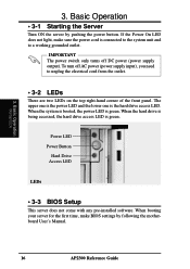
... power LED and the lower one is green. Basic Operation • 3-1 Starting the Server Turn ON the server by following the motherboard User's Manual. 16 AP2300 Reference Guide To turn off DC power (power supply output). When the system is booted, the power LED is the hard drive access LED. When...
... power LED and the lower one is green. Basic Operation • 3-1 Starting the Server Turn ON the server by following the motherboard User's Manual. 16 AP2300 Reference Guide To turn off DC power (power supply output). When the system is booted, the power LED is the hard drive access LED. When...
AP2300 Server in English
Page 17
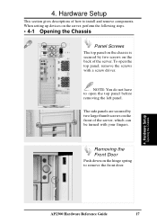
The side panels are secured by two screws on the back of the server. Hardware Setup Opening the Chassis AP2300 Hardware Reference Guide 17 To open the top panel before removing the left panel. NOTE: You do not have to install and remove components. Hardware ...
The side panels are secured by two screws on the back of the server. Hardware Setup Opening the Chassis AP2300 Hardware Reference Guide 17 To open the top panel before removing the left panel. NOTE: You do not have to install and remove components. Hardware ...

AP2300 Server in English
Page 18
... outward while pulling the panel forward. Pulling the panel forward Latches Chassis Circulation System The chassis air circulation system is comprised of the fan. 18 AP2300 Hardware Reference Guide Hardware Setup Chassis Fans Fan Modules There are held by two screws and four latches on the center of two 3 inch (8 cm...
... outward while pulling the panel forward. Pulling the panel forward Latches Chassis Circulation System The chassis air circulation system is comprised of the fan. 18 AP2300 Hardware Reference Guide Hardware Setup Chassis Fans Fan Modules There are held by two screws and four latches on the center of two 3 inch (8 cm...
AP2300 Server in English
Page 19
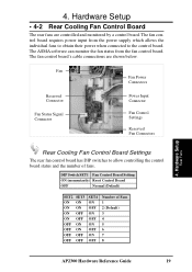
... has DIP switches to the control board. Hardware Setup • 4-2 Rear Cooling Fan Control Board The rear fans are shown below. Hardware Setup Rear Fans AP2300 Hardware Reference Guide 19 The fan control board requires power input from the fan control board. DIP Switch SET1 Fan Control Board Setting ON (momentarily...
... has DIP switches to the control board. Hardware Setup • 4-2 Rear Cooling Fan Control Board The rear fans are shown below. Hardware Setup Rear Fans AP2300 Hardware Reference Guide 19 The fan control board requires power input from the fan control board. DIP Switch SET1 Fan Control Board Setting ON (momentarily...
AP2300 Server in English
Page 20
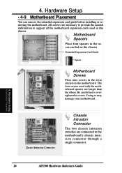
Hardware Setup Motherboard Placement 20 AP2300 Hardware Reference Guide 4. Motherboard Spacers Place four spacers in the areas circled on the chassis. Doing so may damage your motherboard. Extended Expansion Card Guide ...
Hardware Setup Motherboard Placement 20 AP2300 Hardware Reference Guide 4. Motherboard Spacers Place four spacers in the areas circled on the chassis. Doing so may damage your motherboard. Extended Expansion Card Guide ...

AP2300 Server in English
Page 21
... Connector Cable Fan Power Cable Device Cables Several cables are properly secured. 4. Plastic keepers protect the cables from contacting with two 68-pin SCSI connectors. AP2300 Hardware Reference Guide 21 4. Make sure that all cables are used for connecting devices in this chassis.
... Connector Cable Fan Power Cable Device Cables Several cables are properly secured. 4. Plastic keepers protect the cables from contacting with two 68-pin SCSI connectors. AP2300 Hardware Reference Guide 21 4. Make sure that all cables are used for connecting devices in this chassis.