User Manual
Page 1
® AP1700 Intel® Xeon Tower/5U Rackmount Server User's Manual
® AP1700 Intel® Xeon Tower/5U Rackmount Server User's Manual
User Manual
Page 3
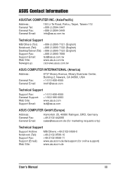
... Road, Peitou, Taipei, Taiwan 112 +886-2-2894-3447 +886-2-2894-3449 info@asus.com.tw Technical Support MB/Others (Tel): +886-2-2890-7121 (English) Notebook (Tel): +886-2-2890-7122 (English) Desktop/Server (Tel): +886-2-2890-7123 (English) Support Fax: +886-2-2890-7698 Support ...Email: tsd@asus.com.tw Web Site: www.asus.com.tw Newsgroup: cscnews.asus.com.tw ASUS COMPUTER INTERNATIONAL (America) Address: General Fax: General Email: 6737 ...
... Road, Peitou, Taipei, Taiwan 112 +886-2-2894-3447 +886-2-2894-3449 info@asus.com.tw Technical Support MB/Others (Tel): +886-2-2890-7121 (English) Notebook (Tel): +886-2-2890-7122 (English) Desktop/Server (Tel): +886-2-2890-7123 (English) Support Fax: +886-2-2890-7698 Support ...Email: tsd@asus.com.tw Web Site: www.asus.com.tw Newsgroup: cscnews.asus.com.tw ASUS COMPUTER INTERNATIONAL (America) Address: General Fax: General Email: 6737 ...
User Manual
Page 7
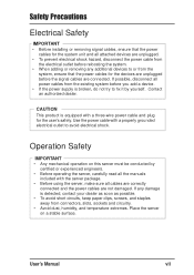
...do not try to fix it by certified or experienced engineers. • Before operating the server, carefully read all the manuals included with the server package. • Before using the server, make sure all cables are correctly connected and the power cables are connected. If any .... • Avoid dust, humidity, and temperature extremes. Operation Safety IMPORTANT • Any mechanical operation on a stable surface. Place the server on this server must be conducted by yourself. Use the power cable with a three-wire power cable and plug for the system unit and all power...
...do not try to fix it by certified or experienced engineers. • Before operating the server, carefully read all the manuals included with the server package. • Before using the server, make sure all cables are correctly connected and the power cables are connected. If any .... • Avoid dust, humidity, and temperature extremes. Operation Safety IMPORTANT • Any mechanical operation on a stable surface. Place the server on this server must be conducted by yourself. Use the power cable with a three-wire power cable and plug for the system unit and all power...
User Manual
Page 10
... contained in this part and try to perform when installing system components. 4. I-2 ASUS AP1700 Chapter 2: Hardware setup This chapter lists the hardware setup procedures that you may refer to this manual. 2. It lists the possible causes of the AP1700 system server. Chapter 1: System overview This chapter describes the general features of the problems and...
... contained in this part and try to perform when installing system components. 4. I-2 ASUS AP1700 Chapter 2: Hardware setup This chapter lists the hardware setup procedures that you may refer to this manual. 2. It lists the possible causes of the AP1700 system server. Chapter 1: System overview This chapter describes the general features of the problems and...
User Manual
Page 11
...perform certain tasks properly, take note of the standard server package. NOTE: Tips and information to complete a task. ASUS PR-DLS Motherboard User's Manual This manual contains detailed information about the PR-DLS motherboard. 2. ASUS Websites The ASUS websites worldwide provide updated information on page v. 3.... this manual. WARNING: Information to prevent injury to yourself when trying to aid in the ASUS Contact Information on ASUS hardware and softare products. The ASUS websites are not part of the following sources for additional information and for product and software ...
...perform certain tasks properly, take note of the standard server package. NOTE: Tips and information to complete a task. ASUS PR-DLS Motherboard User's Manual This manual contains detailed information about the PR-DLS motherboard. 2. ASUS Websites The ASUS websites worldwide provide updated information on page v. 3.... this manual. WARNING: Information to prevent injury to yourself when trying to aid in the ASUS Contact Information on ASUS hardware and softare products. The ASUS websites are not part of the following sources for additional information and for product and software ...

User Manual
Page 12
I-4 ASUS AP1700 System Package Contents The following checklist enumerates the components included in the standard system package. 1) ASUS AS-35 Tower/5U Rackmount chassis 2) ASUS PR-DLS motherboard 3) 500W+500W redundant power supply 4) Backplane board (BP6LS-AS35) 5) CD-ROM drive (1 piece)...hard disk drive tray (6 units) 9) AC power cord (2 pieces) 10) Support CD that includes drivers, utilities, ASUS System Monitoring Agent (ASMA) with the ASUS Server Web-based Management (ASWM) 11) Motherboard user guide 12) System user guide 13) chassis roller wheels (4 sets) Optional...
I-4 ASUS AP1700 System Package Contents The following checklist enumerates the components included in the standard system package. 1) ASUS AS-35 Tower/5U Rackmount chassis 2) ASUS PR-DLS motherboard 3) 500W+500W redundant power supply 4) Backplane board (BP6LS-AS35) 5) CD-ROM drive (1 piece)...hard disk drive tray (6 units) 9) AC power cord (2 pieces) 10) Support CD that includes drivers, utilities, ASUS System Monitoring Agent (ASMA) with the ASUS Server Web-based Management (ASWM) 11) Motherboard user guide 12) System user guide 13) chassis roller wheels (4 sets) Optional...
User Manual
Page 13
User's Manual 1-1 Chapter 1 System Overview This chapter describes the general features of the AP1700 system server. It includes sections on front panel, rear panel and internal specifications.
User's Manual 1-1 Chapter 1 System Overview This chapter describes the general features of the AP1700 system server. It includes sections on front panel, rear panel and internal specifications.
User Manual
Page 14
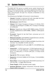
...8226; Power Supply: 500W redundant power supply. • Hardware Monitors: Voltage, temperature, Automatic System Restart (ASR), fan speed. 1-2 ASUS AP1700 Two UltraDMA 100 IDE channels. • Graphics: ATI RAGE-XL PCI with removable front door bezel and chassis foot stand or roller... I /O, LAN, and video technologies through the chipsets embedded on the motherboard. 1.1 System Features The ASUS AP1700 server is a stylish server system featuring the ASUS PR-DLS motherboard. The server supports the Intel® Xeon® processor in a 604-pin socket, and includes the latest I...
...8226; Power Supply: 500W redundant power supply. • Hardware Monitors: Voltage, temperature, Automatic System Restart (ASR), fan speed. 1-2 ASUS AP1700 Two UltraDMA 100 IDE channels. • Graphics: ATI RAGE-XL PCI with removable front door bezel and chassis foot stand or roller... I /O, LAN, and video technologies through the chipsets embedded on the motherboard. 1.1 System Features The ASUS AP1700 server is a stylish server system featuring the ASUS PR-DLS motherboard. The server supports the Intel® Xeon® processor in a 604-pin socket, and includes the latest I...
User Manual
Page 15
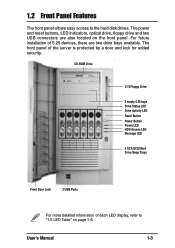
... Button Power LED HDD Access LED Message LED 6 SCA SCSI Hard Drive Swap Trays Front Door Lock 2 USB Ports For more detailed information of the server is protected by a door and lock for added security.
... Button Power LED HDD Access LED Message LED 6 SCA SCSI Hard Drive Swap Trays Front Door Lock 2 USB Ports For more detailed information of the server is protected by a door and lock for added security.
User Manual
Page 16
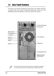
The following shows the features on the rear side of the server. PS/2 mouse port PS/2 keyboard port 2 x USB ports Serial port Parallel port VGA port LAN ports AC Power IN Connector AC Power LED 12 cm chassis fan Chassis Lock 7 Full-Length PCI Slots High Density 68-pin SCSI Connector You may secure the chassis lock with an additional padlock or other security device for added server system security. 1-4 ASUS AP1700 1.3 Rear Panel Features The server rear panel includes the connectors, the system devices, a chassis lock and seven full-length expansion cards slot.
The following shows the features on the rear side of the server. PS/2 mouse port PS/2 keyboard port 2 x USB ports Serial port Parallel port VGA port LAN ports AC Power IN Connector AC Power LED 12 cm chassis fan Chassis Lock 7 Full-Length PCI Slots High Density 68-pin SCSI Connector You may secure the chassis lock with an additional padlock or other security device for added server system security. 1-4 ASUS AP1700 1.3 Rear Panel Features The server rear panel includes the connectors, the system devices, a chassis lock and seven full-length expansion cards slot.
User Manual
Page 17
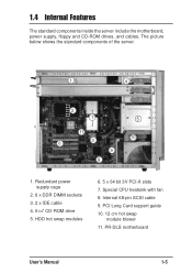
HDD hot swap modules 6. 5 x 64 bit 3V PCI-X slots 7. PCI Long Card support guide 10. 12 cm hot swap module blower 11. Special CPU heatsink with fan 8. 1.4 Internal Features The standard components inside the server include the motherboard, power supply, floppy and CD-ROM drives, and cables. PR-DLS motherboard User's Manual 1-5 The picture below shows the standard components of the server. 1 4 2 7 5 11 6 3 10 9 8 1. Internal 68-pin SCSI cable 9. Redundant power supply cage 2. 6 x DDR DIMM sockets 3. 2 x IDE cable 4. 51/4" CD-ROM drive 5.
HDD hot swap modules 6. 5 x 64 bit 3V PCI-X slots 7. PCI Long Card support guide 10. 12 cm hot swap module blower 11. Special CPU heatsink with fan 8. 1.4 Internal Features The standard components inside the server include the motherboard, power supply, floppy and CD-ROM drives, and cables. PR-DLS motherboard User's Manual 1-5 The picture below shows the standard components of the server. 1 4 2 7 5 11 6 3 10 9 8 1. Internal 68-pin SCSI cable 9. Redundant power supply cage 2. 6 x DDR DIMM sockets 3. 2 x IDE cable 4. 51/4" CD-ROM drive 5.
User Manual
Page 18
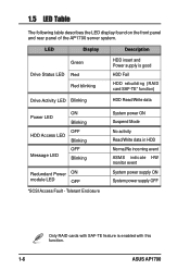
... module LED OFF *SCSI Access Fault - 1.5 LED Table The following table describes the LED display found on the front panel and rear panel of the AP1700 server system. LED Display Description Green Drive Status LED Red Red blinking HDD insert and Power supply is enabled with this function. 1-6 ASUS AP1700
... module LED OFF *SCSI Access Fault - 1.5 LED Table The following table describes the LED display found on the front panel and rear panel of the AP1700 server system. LED Display Description Green Drive Status LED Red Red blinking HDD insert and Power supply is enabled with this function. 1-6 ASUS AP1700
User Manual
Page 34
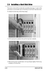
In each of the drive bays is pulled down, the tray will eject slightly. Pull the tray outwards on the tray lever. 2-16 ASUS AP1700 When the tray lever is a removable tray for mounting an SCA SCSI hard disk drive. Lift the spring lock upwards, then pull the tray lever outwards. 2. 2.6 Installing a Hard Disk Drive The server comes with six externally accessible drive bays. To release the drive bay, follow these steps. 1.
In each of the drive bays is pulled down, the tray will eject slightly. Pull the tray outwards on the tray lever. 2-16 ASUS AP1700 When the tray lever is a removable tray for mounting an SCA SCSI hard disk drive. Lift the spring lock upwards, then pull the tray lever outwards. 2. 2.6 Installing a Hard Disk Drive The server comes with six externally accessible drive bays. To release the drive bay, follow these steps. 1.

User Manual
Page 38
Remove the hard drive blower 3-pin power cable (FAN1) from the SCSI backplane. 2. Pull out the blower housing while squeezing the two tabs together. Blower Power Cable 2-20 ASUS AP1700 2.9 Hard Drive Blower The hard drive array is cooled by a blower mounted under the hot swap bays.The drive blower status can be monitored through the ASUS® Server Management Software (ASMS) for remote management convenience. 2.9.1 Removing the hard drive blower To remove the hard drive blower, follow these steps. 1.
Remove the hard drive blower 3-pin power cable (FAN1) from the SCSI backplane. 2. Pull out the blower housing while squeezing the two tabs together. Blower Power Cable 2-20 ASUS AP1700 2.9 Hard Drive Blower The hard drive array is cooled by a blower mounted under the hot swap bays.The drive blower status can be monitored through the ASUS® Server Management Software (ASMS) for remote management convenience. 2.9.1 Removing the hard drive blower To remove the hard drive blower, follow these steps. 1.
User Manual
Page 39
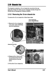
Remove the 12-cm chassis fan 3-pin power cable (SYSFAN3) from the motherboard. Release all four (4) pin-locks by a 12-cm chassis fan mounted at the rear panel.The chassis fan status can be monitored remotely through the ASUS® Server Management Software (ASMS). 2.10.1 Removing the 12-cm chassis fan To remove the 12-cm chassis fan, follow these steps. 12-cm chassis fan power cable (SYSFAN3) 1. Pull out the 12-cm chassis fan. User's Manual 2-21 chassis fan pin-locks 2. 2.10 Chassis Fan The chassis is cooled by squeezing the pin tail and pushing the pin to the rear panel. 3.
Remove the 12-cm chassis fan 3-pin power cable (SYSFAN3) from the motherboard. Release all four (4) pin-locks by a 12-cm chassis fan mounted at the rear panel.The chassis fan status can be monitored remotely through the ASUS® Server Management Software (ASMS). 2.10.1 Removing the 12-cm chassis fan To remove the 12-cm chassis fan, follow these steps. 12-cm chassis fan power cable (SYSFAN3) 1. Pull out the 12-cm chassis fan. User's Manual 2-21 chassis fan pin-locks 2. 2.10 Chassis Fan The chassis is cooled by squeezing the pin tail and pushing the pin to the rear panel. 3.
User Manual
Page 40
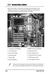
... Access cable 12. SCSI Backplane 12 10 11 7.SMBUS Panel to the motherboard user's manual for detailed information on the motherboard connectors. 2-22 ASUS AP1700 Front USB Connector These are already pre-connected to these connectors. 12 3 5 4 6 7 89 1. External SCSI Connector 11. Refer to... backplane 8. 2.11 Connecting Cables Most of the cables in the server are not the names of the connectors. Primary IDE 6. The following illustrates the corresponding components that are connected to their respective connectors.
... Access cable 12. SCSI Backplane 12 10 11 7.SMBUS Panel to the motherboard user's manual for detailed information on the motherboard connectors. 2-22 ASUS AP1700 Front USB Connector These are already pre-connected to these connectors. 12 3 5 4 6 7 89 1. External SCSI Connector 11. Refer to... backplane 8. 2.11 Connecting Cables Most of the cables in the server are not the names of the connectors. Primary IDE 6. The following illustrates the corresponding components that are connected to their respective connectors.
User Manual
Page 42
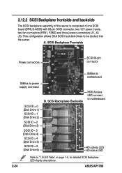
... = 4 (Disk Drive 5) SCSI ID = 5 (Disk Drive 6) B. This configuration allows SCA SCSI hard disk drives to be docked into the server. ASUS AP1700 2.12.2 SCSI Backplane frontside and backside The SCSI backplane assembly of this server is comprised of one SCSI board (BP6LS-AS35) with 68-pin SCSI connector, two 12V power inputs, two fan...
... = 4 (Disk Drive 5) SCSI ID = 5 (Disk Drive 6) B. This configuration allows SCA SCSI hard disk drives to be docked into the server. ASUS AP1700 2.12.2 SCSI Backplane frontside and backside The SCSI backplane assembly of this server is comprised of one SCSI board (BP6LS-AS35) with 68-pin SCSI connector, two 12V power inputs, two fan...
User Manual
Page 43
Appendix A Chassis Roller-wheel This appendix contains the installation procedure for the optional chassis roller-wheel units for the AP1700 server system. User's Manual A-1
Appendix A Chassis Roller-wheel This appendix contains the installation procedure for the optional chassis roller-wheel units for the AP1700 server system. User's Manual A-1
User Manual
Page 44
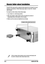
...-wheels, follow these easy steps to mount the chassis roller-wheels. Lay chassis on designated slots at the bottom of the chassis. 3. A-2 ASUS AP1700 Make sure the screws are tightened accordingly. Affix each plastic rubber wheel unit by mounting its built-in chassis-roller wheel brake locks. Follow these...1. chassis roller-wheel brake locks All the chassis roller-wheels can be locked individually with an optional roller-wheel for the chassis for server transport convenience. Chassis Roller-wheel Installation The AP1700 comes with its screws on a side-lying position. 2.
...-wheels, follow these easy steps to mount the chassis roller-wheels. Lay chassis on designated slots at the bottom of the chassis. 3. A-2 ASUS AP1700 Make sure the screws are tightened accordingly. Affix each plastic rubber wheel unit by mounting its built-in chassis-roller wheel brake locks. Follow these...1. chassis roller-wheel brake locks All the chassis roller-wheels can be locked individually with an optional roller-wheel for the chassis for server transport convenience. Chassis Roller-wheel Installation The AP1700 comes with its screws on a side-lying position. 2.
User Manual
Page 46
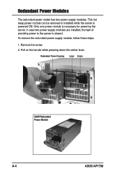
Redundant Power Modules The redundant power model has two power supply modules. Remove the screw. 2. Redundant Power Housing Lever Screw 500W Redundant Power Module A-4 ASUS AP1700 To remove the redundant power supply module, follow these steps. 1. Only one power module is necessary for powering the server, in case two power supply modules are installed, the task of providing power to the server is powered ON. This hot swap power module can be removed or installed while the server is shared. Pull on the handle while pressing down the rubber lever.
Redundant Power Modules The redundant power model has two power supply modules. Remove the screw. 2. Redundant Power Housing Lever Screw 500W Redundant Power Module A-4 ASUS AP1700 To remove the redundant power supply module, follow these steps. 1. Only one power module is necessary for powering the server, in case two power supply modules are installed, the task of providing power to the server is powered ON. This hot swap power module can be removed or installed while the server is shared. Pull on the handle while pressing down the rubber lever.
