User Guide
Page 11
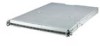
Product introduction Chapter 1 This chapter describes the general features of the chassis kit. ASUS AP1600R-E2 (CS3) 1-1 It includes sections on front panel and rear panel specifications.
Product introduction Chapter 1 This chapter describes the general features of the chassis kit. ASUS AP1600R-E2 (CS3) 1-1 It includes sections on front panel and rear panel specifications.
User Guide
Page 12
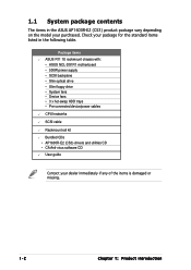
.../power cables CPU heatsinks SCSI cable Rackmount rail kit Bundled CDs • AP1600R-E2 (CS3) drivers and utilities CD • CA Anti-virus software CD User guide Contact your purchased. Check your package for the standard items listed in the ASUS AP1600R-E2 (CS3) product package vary depending on the model your dealer immediately if...
.../power cables CPU heatsinks SCSI cable Rackmount rail kit Bundled CDs • AP1600R-E2 (CS3) drivers and utilities CD • CA Anti-virus software CD User guide Contact your purchased. Check your package for the standard items listed in the ASUS AP1600R-E2 (CS3) product package vary depending on the model your dealer immediately if...
User Guide
Page 13
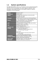
1.2 System specifications The ASUS AP1600R-E2 (CS3) is a 1U barebone server system featuring the ASUS NCL-DS1R1 motherboard. The server supports dual Intel® Xeon™ processors, and includes the latest technologies through the chipsets ...AIC-7902W PCI-X U320 SCSI controller supports: - 2 x SCSI channels - Zero-Channel RAID (via optional ZCR card) ASUS Server Web-based Management (ASWM) Voltage, temperature, and fan speed monitoring Automatic System Restart (ASR) feature 500W power supply, 115V~230V, 50Hz~60Hz 670 mm (l) x 445 mm (w) x 43.6 mm (h) ASUS AP1600R-E2 (CS3) 1-3
1.2 System specifications The ASUS AP1600R-E2 (CS3) is a 1U barebone server system featuring the ASUS NCL-DS1R1 motherboard. The server supports dual Intel® Xeon™ processors, and includes the latest technologies through the chipsets ...AIC-7902W PCI-X U320 SCSI controller supports: - 2 x SCSI channels - Zero-Channel RAID (via optional ZCR card) ASUS Server Web-based Management (ASWM) Voltage, temperature, and fan speed monitoring Automatic System Restart (ASR) feature 500W power supply, 115V~230V, 50Hz~60Hz 670 mm (l) x 445 mm (w) x 43.6 mm (h) ASUS AP1600R-E2 (CS3) 1-3
User Guide
Page 15
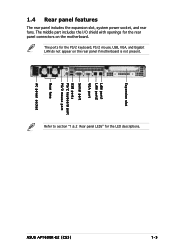
Expansion slot LAN port1 LAN port2 VGA port Serial port USB ports PS/2 keyboard port PS/2 mouse port Rear fans AC power socket ASUS AP1600R-E2 (CS3) 1-5 1.4 Rear panel features The rear panel includes the expansion slot, system power socket, and rear fans. The middle part includes the I/O shield with openings for the rear panel connectors on the rear panel if motherboard is not present. Refer to section "1.6.2 Rear panel LEDs" for the PS/2 keyboard, PS/2 mouse, USB, VGA, and Gigabit LAN do not appear on the motherboard. The ports for the LED descriptions.
Expansion slot LAN port1 LAN port2 VGA port Serial port USB ports PS/2 keyboard port PS/2 mouse port Rear fans AC power socket ASUS AP1600R-E2 (CS3) 1-5 1.4 Rear panel features The rear panel includes the expansion slot, system power socket, and rear fans. The middle part includes the I/O shield with openings for the rear panel connectors on the rear panel if motherboard is not present. Refer to section "1.6.2 Rear panel LEDs" for the PS/2 keyboard, PS/2 mouse, USB, VGA, and Gigabit LAN do not appear on the motherboard. The ports for the LED descriptions.
User Guide
Page 17
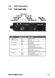
... LEDs OFF Blinking ON Description System power ON No activity Read/write data into the HDD HDD is present No HDD present System is present ASUS AP1600R-E2 (CS3) 1-7
... LEDs OFF Blinking ON Description System power ON No activity Read/write data into the HDD HDD is present No HDD present System is present ASUS AP1600R-E2 (CS3) 1-7
User Guide
Page 19
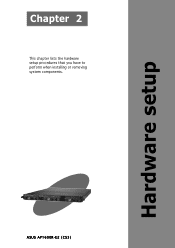
Hardware setup ASUS AP1600R-E2 (CS3) 2-1 Chapter 2 This chapter lists the hardware setup procedures that you have to perform when installing or removing system components.
Hardware setup ASUS AP1600R-E2 (CS3) 2-1 Chapter 2 This chapter lists the hardware setup procedures that you have to perform when installing or removing system components.
User Guide
Page 21
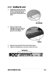
Slide the cover toward the front until it snaps in place. 4. Thumbscrews ASUS AP1600R-E2 (CS3) 2-3 2.1.2 Installing the cover 1. Make sure that the side markings on the cover (two on each side) are aligned to secure the cover. Side markings Grooves 3. Tighten the thumbscrews on the rear to the grooves on the rear, and leaving a gap of the chassis with the thumbscrews on the chassis. Position the cover on top of about half an inch from the front panel. 2.
Slide the cover toward the front until it snaps in place. 4. Thumbscrews ASUS AP1600R-E2 (CS3) 2-3 2.1.2 Installing the cover 1. Make sure that the side markings on the cover (two on each side) are aligned to secure the cover. Side markings Grooves 3. Tighten the thumbscrews on the rear to the grooves on the rear, and leaving a gap of the chassis with the thumbscrews on the chassis. Position the cover on top of about half an inch from the front panel. 2.
User Guide
Page 23
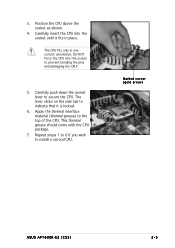
... the socket lever to indicate that it fits in one correct orientation. This thermal grease should come with the CPU package. 7. Marked corner (gold arrow) ASUS AP1600R-E2 (CS3) 2-5 Position the CPU above the socket as shown. 4. 3. The CPU fits only in place. Carefully insert the CPU into the socket to prevent bending...
... the socket lever to indicate that it fits in one correct orientation. This thermal grease should come with the CPU package. 7. Marked corner (gold arrow) ASUS AP1600R-E2 (CS3) 2-5 Position the CPU above the socket as shown. 4. 3. The CPU fits only in place. Carefully insert the CPU into the socket to prevent bending...
User Guide
Page 25
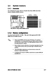
... any three memory sockets will function in single-channel mode. • If installing only one pair of DIMMs, install them in sockets DIMM_B4 and DIMM_A4. ASUS AP1600R-E2 (CS3) 2-7 2.4 System memory 2.4.1 Overview The motherboard comes with four Double Data Rate (DDR) Dual Inline Memory Modules (DIMM) sockets. 104 Pins 80 Pins NCL-DS1R1...
... any three memory sockets will function in single-channel mode. • If installing only one pair of DIMMs, install them in sockets DIMM_B4 and DIMM_A4. ASUS AP1600R-E2 (CS3) 2-7 2.4 System memory 2.4.1 Overview The motherboard comes with four Double Data Rate (DDR) Dual Inline Memory Modules (DIMM) sockets. 104 Pins 80 Pins NCL-DS1R1...
User Guide
Page 27
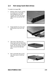
Each side has three holes to the right, then pulling the tray lever outward. The drive tray ejects slightly after you pull out the lever. 2. Take note of the bay. 3. Place a hard disk drive on each side to secure the hard disk drive. 4. 2.4 Hot-swap hard disk drives To install a hot-swap HDD: 1. ASUS AP1600R-E2 (CS3) 2-9 Firmly hold the tray lever and pull the drive tray out of the drive tray holes. Release a drive tray by pushing the spring lock to fit different types of hard disk drives. Use two screws on the tray, then secure it with four screws.
Each side has three holes to the right, then pulling the tray lever outward. The drive tray ejects slightly after you pull out the lever. 2. Take note of the bay. 3. Place a hard disk drive on each side to secure the hard disk drive. 4. 2.4 Hot-swap hard disk drives To install a hot-swap HDD: 1. ASUS AP1600R-E2 (CS3) 2-9 Firmly hold the tray lever and pull the drive tray out of the drive tray holes. Release a drive tray by pushing the spring lock to fit different types of hard disk drives. Use two screws on the tray, then secure it with four screws.
User Guide
Page 29
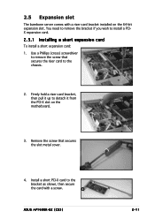
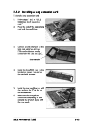
...-bit expansion slot. Remove the screw that secures the riser card to install a PCIX expansion card. 2.5.1 Installing a short expansion card To install a short expansion card: 1. ASUS AP1600R-E2 (CS3) 2-11 Firmly hold a riser card bracket, then pull it up to the bracket as shown, then secure the card with a riser card bracket installed...
...-bit expansion slot. Remove the screw that secures the riser card to install a PCIX expansion card. 2.5.1 Installing a short expansion card To install a short expansion card: 1. ASUS AP1600R-E2 (CS3) 2-11 Firmly hold a riser card bracket, then pull it up to the bracket as shown, then secure the card with a riser card bracket installed...
User Guide
Page 31
ASUS AP1600R-E2 (CS3) 2-13 Follow steps 1 to the bracket as shown, then secure the card with the card into the PCI-X slot on the motherboard. 6. Press the ...
ASUS AP1600R-E2 (CS3) 2-13 Follow steps 1 to the bracket as shown, then secure the card with the card into the PCI-X slot on the motherboard. 6. Press the ...
User Guide
Page 33
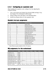
... are usually available for this motherboard ICH5R IDE contrl. PIRQB# - - - - - ICH5R SMBus contrl. AIC-7902W SCSI contrl. REQ1H GNT1 PXH1_B_0 PXH1_B_1 PXH1_B_2 PXH1_B_3 PXH1_B_0 PXH1_B_0 ASUS AP1600R-E2 (CS3) 2-15 2.5.3 Configuring an expansion card After installing the expansion card, configure the it by adjusting the software settings. 1. See Chapter 5 for the expansion card...
... are usually available for this motherboard ICH5R IDE contrl. PIRQB# - - - - - ICH5R SMBus contrl. AIC-7902W SCSI contrl. REQ1H GNT1 PXH1_B_0 PXH1_B_1 PXH1_B_2 PXH1_B_3 PXH1_B_0 PXH1_B_0 ASUS AP1600R-E2 (CS3) 2-15 2.5.3 Configuring an expansion card After installing the expansion card, configure the it by adjusting the software settings. 1. See Chapter 5 for the expansion card...
User Guide
Page 35
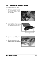
Insert the external SCSI port into the slot opening on the other end (external SCSI port) of the SCSI cable. 2. Secure the port with the white tab) of the cable, and set them aside. 3. Remove the two screws on the rear panel. 4. Screws ASUS AP1600R-E2 (CS3) 2-17 2.6.2 Installing the external SCSI cable To install the external SCSI cable: 1. Locate the SCSI-B connector on Pin 1 the motherboard, and connect one end (with the two screws that you removed earlier.
Insert the external SCSI port into the slot opening on the other end (external SCSI port) of the SCSI cable. 2. Secure the port with the white tab) of the cable, and set them aside. 3. Remove the two screws on the rear panel. 4. Screws ASUS AP1600R-E2 (CS3) 2-17 2.6.2 Installing the external SCSI cable To install the external SCSI cable: 1. Locate the SCSI-B connector on Pin 1 the motherboard, and connect one end (with the two screws that you removed earlier.
User Guide
Page 37
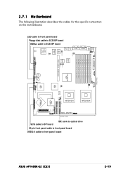
2-19 mPGA 604 ASUS AP1600R-E2 (CS3) USB 2.0 cable to front panel board 20-pin front panel cable to front panel board IDE cable to optical drive ® VGA 30.5cm (...
2-19 mPGA 604 ASUS AP1600R-E2 (CS3) USB 2.0 cable to front panel board 20-pin front panel cable to front panel board IDE cable to optical drive ® VGA 30.5cm (...
User Guide
Page 39
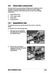
This section tells how to replace defective components. ASUS AP1600R-E2 (CS3) 2-21 2.8 Removable components You may need to remove previously installed system components when installing or removing system devices, or when you need to remove ...
This section tells how to replace defective components. ASUS AP1600R-E2 (CS3) 2-21 2.8 Removable components You may need to remove previously installed system components when installing or removing system devices, or when you need to remove ...
User Guide
Page 41
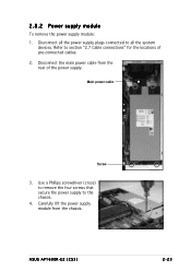
Main power cable Screw 3. Use a Phillips screwdriver (cross) to remove the four screws that secure the power supply to all the system devices. Carefully lift the power supply module from the rear of pre-connected cables. 2. ASUS AP1600R-E2 (CS3) 2-23 Refer to section "2.7 Cable connections" for the locations of the power supply. Disconnect the main power cable from the chassis. Disconnect all the power supply plugs connected to the chassis. 4. 2.8.2 Power supply module To remove the power supply module: 1.
Main power cable Screw 3. Use a Phillips screwdriver (cross) to remove the four screws that secure the power supply to all the system devices. Carefully lift the power supply module from the rear of pre-connected cables. 2. ASUS AP1600R-E2 (CS3) 2-23 Refer to section "2.7 Cable connections" for the locations of the power supply. Disconnect the main power cable from the chassis. Disconnect all the power supply plugs connected to the chassis. 4. 2.8.2 Power supply module To remove the power supply module: 1.
User Guide
Page 43
ASUS AP1600R-E2 (CS3) 2-1 Installation options Chapter 3 This chapter describes how to install the optional components and devices into the barebone server.
ASUS AP1600R-E2 (CS3) 2-1 Installation options Chapter 3 This chapter describes how to install the optional components and devices into the barebone server.
User Guide
Page 45
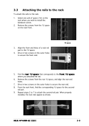
... the front end. 1U space 5. Drive in two screws on the rack where you attached the rail. 6. Drive in two screws on the rack front. 3. ASUS AP1600R-E2 (CS3) 3-3 3.3 Attaching the rails to the rack To attach the rails to secure the rear end. 8. Find the r e a r 1 U s p a c e that corresponds to the 1U space. 4. Remove...
... the front end. 1U space 5. Drive in two screws on the rack where you attached the rail. 6. Drive in two screws on the rack front. 3. ASUS AP1600R-E2 (CS3) 3-3 3.3 Attaching the rails to the rack To attach the rails to secure the rear end. 8. Find the r e a r 1 U s p a c e that corresponds to the 1U space. 4. Remove...
User Guide
Page 47
Motherboard info Chapter 4 This chapter includes the motherboard layout, and brief descriptions of the jumpers and internal connectors. ASUS AP1600R-E2 (CS3)
Motherboard info Chapter 4 This chapter includes the motherboard layout, and brief descriptions of the jumpers and internal connectors. ASUS AP1600R-E2 (CS3)