User Guide
Page 4
... Rackmount rail kit items 3-2 3.2 Rack rails assembly 3-2 3.3 Attaching the rails to the rack 3-3 3.4 Rackmounting the server 3-4 Chapter 4: Motherboard information 4-1 4.1 Motherboard layout 4-2 4.2 Jumpers 4-5 4.3 Connectors 4-10 Chapter 5: BIOS SETUP 5-1 5.1 Managing and ...updating your BIOS 5-2 5.1.1 Creating a bootable floppy disk 5-2 5.1.2 AFUDOS Utility 5-3 5.1.3 ASUS CrashFree BIOS 2 utility 5-6 5.1.4 ASUS Update utility 5-8 5.2 BIOS setup program 5-11 5.2.1 BIOS menu screen 5-12 5.2.2 Menu bar 5-12 5.2.3 Navigation keys 5-12 ...
... Rackmount rail kit items 3-2 3.2 Rack rails assembly 3-2 3.3 Attaching the rails to the rack 3-3 3.4 Rackmounting the server 3-4 Chapter 4: Motherboard information 4-1 4.1 Motherboard layout 4-2 4.2 Jumpers 4-5 4.3 Connectors 4-10 Chapter 5: BIOS SETUP 5-1 5.1 Managing and ...updating your BIOS 5-2 5.1.1 Creating a bootable floppy disk 5-2 5.1.2 AFUDOS Utility 5-3 5.1.3 ASUS CrashFree BIOS 2 utility 5-6 5.1.4 ASUS Update utility 5-8 5.2 BIOS setup program 5-11 5.2.1 BIOS menu screen 5-12 5.2.2 Menu bar 5-12 5.2.3 Navigation keys 5-12 ...
User Guide
Page 7
... by yourself. Use the power cable with a three-wire power cable and plug for assistance when moving or carrying the system. This server system is incorrectly replaced. Ask for the user's safety. If possible, disconnect all cables are correctly connected and the power cables are not... to fix it by the manufacturer. This product is broken, do not try to avoid electrical shock. Replace only with the server package. • Before using the server, make sure all power cables from connectors, slots, sockets and circuitry. • Avoid dust, humidity, and temperature extremes....
... by yourself. Use the power cable with a three-wire power cable and plug for assistance when moving or carrying the system. This server system is incorrectly replaced. Ask for the user's safety. If possible, disconnect all cables are correctly connected and the power cables are not... to fix it by the manufacturer. This product is broken, do not try to avoid electrical shock. Replace only with the server package. • Before using the server, make sure all power cables from connectors, slots, sockets and circuitry. • Avoid dust, humidity, and temperature extremes....
User Guide
Page 8
Contents This guide contains the following parts: 1. Chapter 1: Product Introduction This chapter describes the general features of configuring a server. Chapter 3: Installation options This chapter describes how to change system settings through the BIOS Setup menus and describes the BIOS parameters. ...Chapter 5: BIOS information This chapter tells how to install optional components into the barebone server. 4 . Chapter 2: Hardware setup This chapter lists the hardware setup procedures that comes with at least basic knowledge of the...
Contents This guide contains the following parts: 1. Chapter 1: Product Introduction This chapter describes the general features of configuring a server. Chapter 3: Installation options This chapter describes how to change system settings through the BIOS Setup menus and describes the BIOS parameters. ...Chapter 5: BIOS information This chapter tells how to install optional components into the barebone server. 4 . Chapter 2: Hardware setup This chapter lists the hardware setup procedures that comes with at least basic knowledge of the...
User Guide
Page 9
W A R N I M P O R T A N T : Instructions that you MUST follow to complete a task. N O T E : Tips and information to set up and use the proprietary ASUS server management utility. 3. ASUS Server Web-based Management (ASWM) user guide This manual tells how to aid in completing a task. I N G : Information to prevent injury to yourself when trying to complete a ...
W A R N I M P O R T A N T : Instructions that you MUST follow to complete a task. N O T E : Tips and information to set up and use the proprietary ASUS server management utility. 3. ASUS Server Web-based Management (ASWM) user guide This manual tells how to aid in completing a task. I N G : Information to prevent injury to yourself when trying to complete a ...
User Guide
Page 13
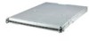
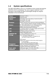
...the motherboard. Zero-Channel RAID (via optional ZCR card) ASUS Server Web-based Management (ASWM) Voltage, temperature, and fan speed monitoring Automatic System Restart (ASR) feature 500W power supply, 115V~230V, 50Hz~60Hz 670 mm (l) x 445 mm (w) x 43.6 mm (h) ASUS AP1600R-E2 (CS3) 1-3 Chassis Motherboard Chipset Processor Memory LAN... Intel® Matrix Storage Technology (SCSI feature) Adaptec AIC-7902W PCI-X U320 SCSI controller supports: - 2 x SCSI channels - 1.2 System specifications The ASUS AP1600R-E2 (CS3) is a 1U barebone server system featuring the ASUS NCL-DS1R1 motherboard.
...the motherboard. Zero-Channel RAID (via optional ZCR card) ASUS Server Web-based Management (ASWM) Voltage, temperature, and fan speed monitoring Automatic System Restart (ASR) feature 500W power supply, 115V~230V, 50Hz~60Hz 670 mm (l) x 445 mm (w) x 43.6 mm (h) ASUS AP1600R-E2 (CS3) 1-3 Chassis Motherboard Chipset Processor Memory LAN... Intel® Matrix Storage Technology (SCSI feature) Adaptec AIC-7902W PCI-X U320 SCSI controller supports: - 2 x SCSI channels - 1.2 System specifications The ASUS AP1600R-E2 (CS3) is a 1U barebone server system featuring the ASUS NCL-DS1R1 motherboard.
User Guide
Page 14
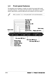
... button Location LED Location switch Power LED Power button Hot-swap HDD bay 2 Hot-swap HDD bay 3 1-4 Chapter 1: Product introduction 1.3 Front panel features The barebone server displays a simple yet stylish front panel with easily accessible features. Refer to section "1.6.1 Front panel LEDs" for the LED descriptions. The power and reset buttons...
... button Location LED Location switch Power LED Power button Hot-swap HDD bay 2 Hot-swap HDD bay 3 1-4 Chapter 1: Product introduction 1.3 Front panel features The barebone server displays a simple yet stylish front panel with easily accessible features. Refer to section "1.6.1 Front panel LEDs" for the LED descriptions. The power and reset buttons...
User Guide
Page 16
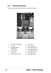
Device fan 8. Hot-swap HDD tray 3 12. Power supply 5. Slim floppy drive 1-6 Chapter 1: Product introduction Rear fans 3. System fans (8 fans) 7. PCI-X riser card bracket 2. Hot-swap HDD tray 2 11. SCSI backplane 9. Slim optical drive 13. 1.5 Internal features The barebone server includes the basic components as shown. 2 13 4 5 6 7 8 9 10 11 12 13 1. ASUS NCL-DS1R1 motherboard 4. Device fan 6. Hot-swap HDD tray 1 10.
Device fan 8. Hot-swap HDD tray 3 12. Power supply 5. Slim floppy drive 1-6 Chapter 1: Product introduction Rear fans 3. System fans (8 fans) 7. PCI-X riser card bracket 2. Hot-swap HDD tray 2 11. SCSI backplane 9. Slim optical drive 13. 1.5 Internal features The barebone server includes the basic components as shown. 2 13 4 5 6 7 8 9 10 11 12 13 1. ASUS NCL-DS1R1 motherboard 4. Device fan 6. Hot-swap HDD tray 1 10.
User Guide
Page 29
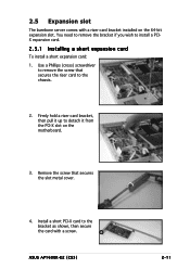
... the screw that secures the riser card to install a PCIX expansion card. 2.5.1 Installing a short expansion card To install a short expansion card: 1. 2.5 Expansion slot The barebone server comes with a screw. Use a Phillips (cross) screwdriver to remove the screw that secures the slot metal cover. 4. Install a short PCI-X card to detach it up... a riser card bracket installed on the motherboard. 3. Firmly hold a riser card bracket, then pull it from the PCI-X slot on the 64-bit expansion slot. ASUS AP1600R-E2 (CS3) 2-11
... the screw that secures the riser card to install a PCIX expansion card. 2.5.1 Installing a short expansion card To install a short expansion card: 1. 2.5 Expansion slot The barebone server comes with a screw. Use a Phillips (cross) screwdriver to remove the screw that secures the slot metal cover. 4. Install a short PCI-X card to detach it up... a riser card bracket installed on the motherboard. 3. Firmly hold a riser card bracket, then pull it from the PCI-X slot on the 64-bit expansion slot. ASUS AP1600R-E2 (CS3) 2-11
User Guide
Page 43
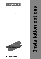
ASUS AP1600R-E2 (CS3) 2-1 Installation options Chapter 3 This chapter describes how to install the optional components and devices into the barebone server.
ASUS AP1600R-E2 (CS3) 2-1 Installation options Chapter 3 This chapter describes how to install the optional components and devices into the barebone server.
User Guide
Page 45
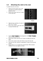
... outer holes to the 1U space. 4. When properly installed, the rack rails appear as shown. ASUS AP1600R-E2 (CS3) 3-3 Select one unit of a rack rail pair to secure the rear end. 8. Repeat steps 2 to 7 to install the barebone server. 2. Remove the screws from the rear 1U space, and align the rear end holes...
... outer holes to the 1U space. 4. When properly installed, the rack rails appear as shown. ASUS AP1600R-E2 (CS3) 3-3 Select one unit of a rack rail pair to secure the rear end. 8. Repeat steps 2 to 7 to install the barebone server. 2. Remove the screws from the rear 1U space, and align the rear end holes...
User Guide
Page 46
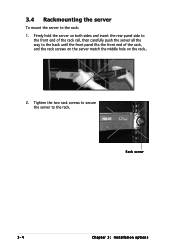
Firmly hold the server on the rack.. 2. Rack screw 3-4 Chapter 3: Installation options Tighten the two rack screws to secure the server to the back until the front panel fits the front end of the rack, and the rack screws on the server match the middle hole on both sides and insert the rear panel side to the front end of the rack rail, then carefully push the server all the way to the rack. 3.4 Rackmounting the server To mount the server to the rack: 1.
Firmly hold the server on the rack.. 2. Rack screw 3-4 Chapter 3: Installation options Tighten the two rack screws to secure the server to the back until the front panel fits the front end of the rack, and the rack screws on the server match the middle hole on both sides and insert the rear panel side to the front end of the rack rail, then carefully push the server all the way to the rack. 3.4 Rackmounting the server To mount the server to the rack: 1.
User Guide
Page 63
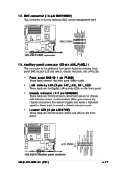
... 12CDATA1 FP_PWRBTN# BMC_PRESENT# BMC_SMI# GND 12. NC I2C_4_CLK# GND I2C_4_DATA# +5VSB LAN1_LINKACTLED+ LAN1_LINKACTLEDLAN2_LINKACTLEDLAN2_LINKACTLED+ ® NCL-DS1R1 AUX_PANEL1 PIN1 NCL-DS1R1 Auxiliary panel connector ASUS AP1600R-E2 (CS3) +5VSB CASEOPEN GND LOCATORLED1+ LOCATORLED1LOCATORBTN# GND LOCATORLED2LOCATORLED2+ 4-17 BMCCONN1 NCL-DS1R1 BMC connector 13. BMC connector (16-pin BMCCONN1) This connector is... These leads are for Gigabit LAN activity LEDs on the front panel. • Chassis intrusion (4-1 pin CHASSIS) These leads are for the optional ASUS server management card.
... 12CDATA1 FP_PWRBTN# BMC_PRESENT# BMC_SMI# GND 12. NC I2C_4_CLK# GND I2C_4_DATA# +5VSB LAN1_LINKACTLED+ LAN1_LINKACTLEDLAN2_LINKACTLEDLAN2_LINKACTLED+ ® NCL-DS1R1 AUX_PANEL1 PIN1 NCL-DS1R1 Auxiliary panel connector ASUS AP1600R-E2 (CS3) +5VSB CASEOPEN GND LOCATORLED1+ LOCATORLED1LOCATORBTN# GND LOCATORLED2LOCATORLED2+ 4-17 BMCCONN1 NCL-DS1R1 BMC connector 13. BMC connector (16-pin BMCCONN1) This connector is... These leads are for Gigabit LAN activity LEDs on the front panel. • Chassis intrusion (4-1 pin CHASSIS) These leads are for the optional ASUS server management card.
