User Guide
Page 3
Contents Contents iii Safety information vi About this guide viii ASUS contact information x Chapter 1: Product introduction 1.1 System package contents 1-2 1.2 System specifications 1-3 1.3 Front panel features 1-4 1.4 LED information... 2.5.2 DIMM installation 2-9 2.5.3 Removing a DIMM 2-9 2.6 Installing a hard disk drive 2-10 2.6.1 Qualified hard disk drives 2-10 2.6.2 Hard disk drive installation 2-11 2.7 Installing 5.25-inch drives 2-13 2.7.1 Removing the front panel cover 2-13 2.7.2 Installing additional optical drive(s 2-15 2.8 Installing expansion cards 2-17 2.9 Removing...
Contents Contents iii Safety information vi About this guide viii ASUS contact information x Chapter 1: Product introduction 1.1 System package contents 1-2 1.2 System specifications 1-3 1.3 Front panel features 1-4 1.4 LED information... 2.5.2 DIMM installation 2-9 2.5.3 Removing a DIMM 2-9 2.6 Installing a hard disk drive 2-10 2.6.1 Qualified hard disk drives 2-10 2.6.2 Hard disk drive installation 2-11 2.7 Installing 5.25-inch drives 2-13 2.7.1 Removing the front panel cover 2-13 2.7.2 Installing additional optical drive(s 2-15 2.8 Installing expansion cards 2-17 2.9 Removing...
User Guide
Page 16
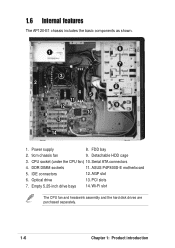
Optical drive 13. 1.6 Internal features The AP120-E1 chassis includes the basic components as shown. 6 1 7 3 2 8 45 11 12 9 10 13 14 1. PCI slots 7. Empty 5.25-inch drive bays 14. AGP slot 6. FDD bay 2. 9cm chassis fan 9. Serial ATA connectors 4. ASUS P4P800S-E motherboard 5. IDE connectors 12. Power supply 8. Detachable HDD cage 3. DDR DIMM sockets 11. Wi-Fi slot The CPU fan and heatswink assembly and the hard disk drives are purchased separately. 1-6 Chapter 1: Product introduction CPU socket (under the CPU fan) 10.
Optical drive 13. 1.6 Internal features The AP120-E1 chassis includes the basic components as shown. 6 1 7 3 2 8 45 11 12 9 10 13 14 1. PCI slots 7. Empty 5.25-inch drive bays 14. AGP slot 6. FDD bay 2. 9cm chassis fan 9. Serial ATA connectors 4. ASUS P4P800S-E motherboard 5. IDE connectors 12. Power supply 8. Detachable HDD cage 3. DDR DIMM sockets 11. Wi-Fi slot The CPU fan and heatswink assembly and the hard disk drives are purchased separately. 1-6 Chapter 1: Product introduction CPU socket (under the CPU fan) 10.
User Guide
Page 27
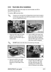
DO NOT install a hard disk drive to the lower bay of the cage. Secure the HDD to the upper bay of the cage. 3 3. ASUS AP120-E1 user guide 2-11 Re-install the HDD cage to the drive cage. Press the HDD cage lock while pulling the cage out from the chassis. Place the HDD ...
DO NOT install a hard disk drive to the lower bay of the cage. Secure the HDD to the upper bay of the cage. 3 3. ASUS AP120-E1 user guide 2-11 Re-install the HDD cage to the drive cage. Press the HDD cage lock while pulling the cage out from the chassis. Place the HDD ...
User Guide
Page 37
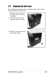
Slide the cover toward the chassis until it fits. 1 3. Fit the side cover the cover toward the front until it snaps in place. 3 ASUS AP120-E1 user guide 2-21 2.11 Replacing the side cover After installing all components and re-connecting cables, replace the side cover by following these instructions. 1. Match the side cover hooks to the chassis rail on the side of the chassis. 2 2.
Slide the cover toward the chassis until it fits. 1 3. Fit the side cover the cover toward the front until it snaps in place. 3 ASUS AP120-E1 user guide 2-21 2.11 Replacing the side cover After installing all components and re-connecting cables, replace the side cover by following these instructions. 1. Match the side cover hooks to the chassis rail on the side of the chassis. 2 2.