Motherboard DIY Troubleshooting Guide
Page 1
® A7VL133-VM PC133/VC133 200/266 MHz FSB AGP 4X Socket A Motherboard USER'S MANUAL
® A7VL133-VM PC133/VC133 200/266 MHz FSB AGP 4X Socket A Motherboard USER'S MANUAL
Motherboard DIY Troubleshooting Guide
Page 8
...options. • PC Health Monitoring: Provides an easy way to 100MB/ sec; FEATURES 2.1 The ASUS A7VL133-VM The ASUS A7VL133-VM motherboard is enabled. USB controller with root hub and four function ports. • PC133 SDRAM: ...Socket A-based AMD Athlon™/Duron™ processors. • North Bridge System Chipset: Features the VIA VT8364A (VIA KL133A) system controller with AGP 2.0 specifications for UltraDMA/100, which allows burst mode data transfer rates of frequency and Vcore voltage all through the onboard hardware ASUS ASIC and the bundled ASUS PC Probe. 8 ASUS A7VL133-VM...
...options. • PC Health Monitoring: Provides an easy way to 100MB/ sec; FEATURES 2.1 The ASUS A7VL133-VM The ASUS A7VL133-VM motherboard is enabled. USB controller with root hub and four function ports. • PC133 SDRAM: ...Socket A-based AMD Athlon™/Duron™ processors. • North Bridge System Chipset: Features the VIA VT8364A (VIA KL133A) system controller with AGP 2.0 specifications for UltraDMA/100, which allows burst mode data transfer rates of frequency and Vcore voltage all through the onboard hardware ASUS ASIC and the bundled ASUS PC Probe. 8 ASUS A7VL133-VM...
Motherboard DIY Troubleshooting Guide
Page 12
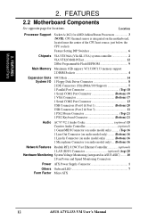
... controller 2 VIA VT82C686B PCIset 12 2Mbit Programmable Flash EEPROM 9 Main Memory Maximum 1GB support, VC133/PC133 memory support 2 DIMM Sockets 4 Expansion Slots System I/O 3PCI Slots 14 1 Floppy Disk Driver Connector 8 2 IDE Connectors (UltraDMA/100 Support 5 1 ...System Voltage Monitoring (integrated in ASUS ASIC) ....... 10 2 Fan Power and Speed Monitoring Connectors Power ATX Power Supply Connector 1 Others Onboard LED 7 Form Factor Micro ATX 12 ASUS A7VL133-VM User's Manual FEATURES Motherboard Parts 2. Location Processor Support Socket A (462) for locations. ...
... controller 2 VIA VT82C686B PCIset 12 2Mbit Programmable Flash EEPROM 9 Main Memory Maximum 1GB support, VC133/PC133 memory support 2 DIMM Sockets 4 Expansion Slots System I/O 3PCI Slots 14 1 Floppy Disk Driver Connector 8 2 IDE Connectors (UltraDMA/100 Support 5 1 ...System Voltage Monitoring (integrated in ASUS ASIC) ....... 10 2 Fan Power and Speed Monitoring Connectors Power ATX Power Supply Connector 1 Others Onboard LED 7 Form Factor Micro ATX 12 ASUS A7VL133-VM User's Manual FEATURES Motherboard Parts 2. Location Processor Support Socket A (462) for locations. ...
Motherboard DIY Troubleshooting Guide
Page 14
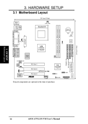
... 24.5cm (9.6in) 3. 3. H/W SETUP Motherboard Layout 14 ASUS A7VL133-VM User's Manual HARDWARE SETUP 3.1 Motherboard Layout PS/2 T: Mouse B: Keyboard USB Top: T: USB1 RJ-45 B: USB2 COM1 24.5cm (9.6in) CPU_FAN Socket A CR2032 3V Lithium Cell CMOS Power LED CLRTC DIMM Socket 1 (64/72-bit, 168-pin module) DIMM Socket 2 (64/72-bit, 168-pin module) PARALLEL...
... 24.5cm (9.6in) 3. 3. H/W SETUP Motherboard Layout 14 ASUS A7VL133-VM User's Manual HARDWARE SETUP 3.1 Motherboard Layout PS/2 T: Mouse B: Keyboard USB Top: T: USB1 RJ-45 B: USB2 COM1 24.5cm (9.6in) CPU_FAN Socket A CR2032 3V Lithium Cell CMOS Power LED CLRTC DIMM Socket 1 (64/72-bit, 168-pin module) DIMM Socket 2 (64/72-bit, 168-pin module) PARALLEL...
Motherboard DIY Troubleshooting Guide
Page 15
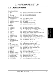
3. HARDWARE SETUP 3.2 Layout Contents Motherboard Settings 1) JEN 2) JF 2) SW1 1-4 Expansion Slots/Sockets 1) System Memory 2) DIMM1/2 3) Socket 462 (Socket A) 4) PCI1/2/3 5) AGP Connectors 1) PS2KBMS 2) PS2KBMS 3) USB 4) PRINTER 5) VGA 6) COM1/2 7) GAME_AUDIO 8) GAME_AUDIO 9) RJ45 10) PRIMARY IDE SECONDARY IDE 11) FLOPPY 12) IR 13) CPU_FAN, PS_FAN 14) ... (4 pin) p.37 System Power LED Lead (3 pin) p.37 Reset Switch Lead (2 pin) p.37 ATX / Soft-Off Switch Lead (2 pin) p.37 System Management Interrupt Lead (2 pin) ASUS A7VL133-VM User's Manual 15 H/W SETUP Layout Contents 3.
3. HARDWARE SETUP 3.2 Layout Contents Motherboard Settings 1) JEN 2) JF 2) SW1 1-4 Expansion Slots/Sockets 1) System Memory 2) DIMM1/2 3) Socket 462 (Socket A) 4) PCI1/2/3 5) AGP Connectors 1) PS2KBMS 2) PS2KBMS 3) USB 4) PRINTER 5) VGA 6) COM1/2 7) GAME_AUDIO 8) GAME_AUDIO 9) RJ45 10) PRIMARY IDE SECONDARY IDE 11) FLOPPY 12) IR 13) CPU_FAN, PS_FAN 14) ... (4 pin) p.37 System Power LED Lead (3 pin) p.37 Reset Switch Lead (2 pin) p.37 ATX / Soft-Off Switch Lead (2 pin) p.37 System Management Interrupt Lead (2 pin) ASUS A7VL133-VM User's Manual 15 H/W SETUP Layout Contents 3.
Motherboard DIY Troubleshooting Guide
Page 20
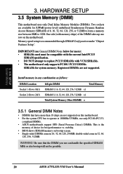
... • Single-sided DIMMs come in 16, 32, 64,128, 256MB; H/W SETUP System Memory 3. Install memory in any combination as follows: DIMM Location Socket 1 (Rows 0&1) Socket 2 (Rows 2&3) 168-pin DIMM Total Memory SDRAM 8, 16, 32, 64, 128, 256, 512MB x1 SDRAM 8, 16, 32, 64, 128, 256,...Notes • DIMMs that the DIMM you use only PC100-/PC133- Be sure that have more ): • SDRAMs used must be possible. 20 ASUS A7VL133-VM User's Manual IMPORTANT (see General DIMM Notes below for more than 18 chips are not supported. HARDWARE SETUP 3.5 System Memory (DIMM) This motherboard ...
... • Single-sided DIMMs come in 16, 32, 64,128, 256MB; H/W SETUP System Memory 3. Install memory in any combination as follows: DIMM Location Socket 1 (Rows 0&1) Socket 2 (Rows 2&3) 168-pin DIMM Total Memory SDRAM 8, 16, 32, 64, 128, 256, 512MB x1 SDRAM 8, 16, 32, 64, 128, 256,...Notes • DIMMs that the DIMM you use only PC100-/PC133- Be sure that have more ): • SDRAMs used must be possible. 20 ASUS A7VL133-VM User's Manual IMPORTANT (see General DIMM Notes below for more than 18 chips are not supported. HARDWARE SETUP 3.5 System Memory (DIMM) This motherboard ...
Motherboard DIY Troubleshooting Guide
Page 21
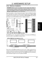
...figure below). 168-Pin DIMM Notch Key Definitions (3.3V) 3. Make sure that you unplug your retailer the correct DIMM type before purchasing. ASUS A7VL133-VM User's Manual 21 Failure to do so may cause severe damage to prevent the wrong type from being inserted into the DIMM slot on ...motherboard supports four clock signals per DIMM. DRAM SIMM modules have a higher pin density. 20 Pins 60 Pins 88 Pins A7VL133-VM ® A7VL133-VM 168-Pin DIMM Sockets The DIMMs must tell your power supply when adding or removing memory modules or other system components. Because the number of the...
...figure below). 168-Pin DIMM Notch Key Definitions (3.3V) 3. Make sure that you unplug your retailer the correct DIMM type before purchasing. ASUS A7VL133-VM User's Manual 21 Failure to do so may cause severe damage to prevent the wrong type from being inserted into the DIMM slot on ...motherboard supports four clock signals per DIMM. DRAM SIMM modules have a higher pin density. 20 Pins 60 Pins 88 Pins A7VL133-VM ® A7VL133-VM 168-Pin DIMM Sockets The DIMMs must tell your power supply when adding or removing memory modules or other system components. Because the number of the...

Motherboard DIY Troubleshooting Guide
Page 23
... heatsink/CPU documentation. Carefully attach the heatsink locking brace to 100 degrees). 2. Once completely inserted, press the CPU firmly and close the socket lever until it by pulling the lever gently sideways away from the socket. 3. With the added weight of the socket base nearest to avoid start-up problems. ASUS A7VL133-VM User's Manual 23
... heatsink/CPU documentation. Carefully attach the heatsink locking brace to 100 degrees). 2. Once completely inserted, press the CPU firmly and close the socket lever until it by pulling the lever gently sideways away from the socket. 3. With the added weight of the socket base nearest to avoid start-up problems. ASUS A7VL133-VM User's Manual 23
Motherboard DIY Troubleshooting Guide
Page 90
...alphanumeric character, punctuation mark, or other programs and software applications operate, including Windows. DRAM (Dynamic Random Access Memory) There are socket 370 (for Pentium III FC-PGA and CeleronPPGA), socket 7 (for Pentium, AMD, Cyrix, IBM), slot 1 (for Pentium II and III), slot 2 (for Xeon), and ...circuitry directly on which initiates hardware devices and sets up to restart your computer. "Reboot" means to 33MB/Sec transfer. 90 ASUS A7VL133-VM User's Manual Bus master IDE transfers data to support bus master IDE mode. Normally, the flash ROM is responsible for the ...
...alphanumeric character, punctuation mark, or other programs and software applications operate, including Windows. DRAM (Dynamic Random Access Memory) There are socket 370 (for Pentium III FC-PGA and CeleronPPGA), socket 7 (for Pentium, AMD, Cyrix, IBM), slot 1 (for Pentium II and III), slot 2 (for Xeon), and ...circuitry directly on which initiates hardware devices and sets up to restart your computer. "Reboot" means to 33MB/Sec transfer. 90 ASUS A7VL133-VM User's Manual Bus master IDE transfers data to support bus master IDE mode. Normally, the flash ROM is responsible for the ...


