Motherboard DIY Troubleshooting Guide
Page 12
... controller 2 VIA VT82C686B PCIset 12 2Mbit Programmable Flash EEPROM 9 Main Memory Maximum 1GB support, VC133/PC133 memory support 2 DIMM Sockets 4 Expansion Slots System I/O 3PCI Slots 14 1 Floppy Disk Driver Connector 8 2 IDE Connectors (UltraDMA/100 Support 5 1 Parallel... 20 Hardware Monitoring System Voltage Monitoring (integrated in ASUS ASIC) ....... 10 2 Fan Power and Speed Monitoring Connectors Power ATX Power Supply Connector 1 Others Onboard LED 7 Form Factor Micro ATX 12 ASUS A7VL133-VM User's Manual Location Processor Support Socket A (462) for locations.
... controller 2 VIA VT82C686B PCIset 12 2Mbit Programmable Flash EEPROM 9 Main Memory Maximum 1GB support, VC133/PC133 memory support 2 DIMM Sockets 4 Expansion Slots System I/O 3PCI Slots 14 1 Floppy Disk Driver Connector 8 2 IDE Connectors (UltraDMA/100 Support 5 1 Parallel... 20 Hardware Monitoring System Voltage Monitoring (integrated in ASUS ASIC) ....... 10 2 Fan Power and Speed Monitoring Connectors Power ATX Power Supply Connector 1 Others Onboard LED 7 Form Factor Micro ATX 12 ASUS A7VL133-VM User's Manual Location Processor Support Socket A (462) for locations.
Motherboard DIY Troubleshooting Guide
Page 15
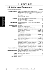
H/W SETUP Layout Contents 3. HARDWARE SETUP 3.2 Layout Contents Motherboard Settings 1) JEN 2) JF 2) SW1 1-4 Expansion Slots/Sockets 1) System Memory 2) DIMM1/2 3) Socket 462 (Socket A) 4) PCI1/2/3 5) AGP Connectors 1) PS2KBMS 2) PS2KBMS 3) USB 4) PRINTER 5) VGA 6) COM1/2 7) GAME_AUDIO 8) GAME_AUDIO 9) RJ45 10) PRIMARY IDE SECONDARY IDE 11) FLOPPY 12) IR 13) CPU_FAN, PS_FAN 14) ... (4 pin) p.37 System Power LED Lead (3 pin) p.37 Reset Switch Lead (2 pin) p.37 ATX / Soft-Off Switch Lead (2 pin) p.37 System Management Interrupt Lead (2 pin) ASUS A7VL133-VM User's Manual 15 3.
H/W SETUP Layout Contents 3. HARDWARE SETUP 3.2 Layout Contents Motherboard Settings 1) JEN 2) JF 2) SW1 1-4 Expansion Slots/Sockets 1) System Memory 2) DIMM1/2 3) Socket 462 (Socket A) 4) PCI1/2/3 5) AGP Connectors 1) PS2KBMS 2) PS2KBMS 3) USB 4) PRINTER 5) VGA 6) COM1/2 7) GAME_AUDIO 8) GAME_AUDIO 9) RJ45 10) PRIMARY IDE SECONDARY IDE 11) FLOPPY 12) IR 13) CPU_FAN, PS_FAN 14) ... (4 pin) p.37 System Power LED Lead (3 pin) p.37 Reset Switch Lead (2 pin) p.37 ATX / Soft-Off Switch Lead (2 pin) p.37 System Management Interrupt Lead (2 pin) ASUS A7VL133-VM User's Manual 15 3.

Motherboard DIY Troubleshooting Guide
Page 23
...required to avoid start-up problems. ASUS A7VL133-VM User's Manual 23 Take care not to set the correct Bus Frequency and Multiple (available only on the CPU. BLANK LEVER 3. Once completely inserted, press the CPU firmly and close the socket lever until it by pulling the ... a clamp-style processor fan, or else damage may occur! Do not force the CPU into the socket to heatsink/CPU documentation. CAUTION! NOTE! HARDWARE SETUP 3.6 Central Processing Unit (CPU) The motherboard provides a Socket 462 or Socket A for bent pins. 3. A fan and heatsink should entirely cover the CPU.
...required to avoid start-up problems. ASUS A7VL133-VM User's Manual 23 Take care not to set the correct Bus Frequency and Multiple (available only on the CPU. BLANK LEVER 3. Once completely inserted, press the CPU firmly and close the socket lever until it by pulling the ... a clamp-style processor fan, or else damage may occur! Do not force the CPU into the socket to heatsink/CPU documentation. CAUTION! NOTE! HARDWARE SETUP 3.6 Central Processing Unit (CPU) The motherboard provides a Socket 462 or Socket A for bent pins. 3. A fan and heatsink should entirely cover the CPU.


