Motherboard DIY Troubleshooting Guide
Page 1
® A7V266 JumperFree™ DDR DRAM 266MHz FSB AGP Pro/4X Socket A Motherboard USER'S MANUAL
® A7V266 JumperFree™ DDR DRAM 266MHz FSB AGP Pro/4X Socket A Motherboard USER'S MANUAL

Motherboard DIY Troubleshooting Guide
Page 4
...Program 49 4.2.1 BIOS Menu Bar 50 4.2.2 Legend Bar 50 4 ASUS A7V266 User's Manual HARDWARE SETUP 14 3.1 Motherboard Layout 14 3.2 Layout Contents 15 3.3 Hardware Setup Procedure 17 3.4 Motherboard Settings 17 3.5 System Memory 25 3.5.1 DDR DIMM Support 25 3.5.1... External Connectors 31 3.9 Starting Up the First Time 44 4. FEATURES 8 2.1 ASUS A7V266 Motherboard 8 2.1.1 Specifications 8 2.1.2 Performance 10 2.1.3 Intelligence 11 2.2 Motherboard Components 12 2.2.1 Component Locations 13 3. CONTENTS 1. INTRODUCTION 7 1.1 How This Manual Is Organized 7 1.2 Item Checklist ...
...Program 49 4.2.1 BIOS Menu Bar 50 4.2.2 Legend Bar 50 4 ASUS A7V266 User's Manual HARDWARE SETUP 14 3.1 Motherboard Layout 14 3.2 Layout Contents 15 3.3 Hardware Setup Procedure 17 3.4 Motherboard Settings 17 3.5 System Memory 25 3.5.1 DDR DIMM Support 25 3.5.1... External Connectors 31 3.9 Starting Up the First Time 44 4. FEATURES 8 2.1 ASUS A7V266 Motherboard 8 2.1.1 Specifications 8 2.1.2 Performance 10 2.1.3 Intelligence 11 2.2 Motherboard Components 12 2.2.1 Component Locations 13 3. CONTENTS 1. INTRODUCTION 7 1.1 How This Manual Is Organized 7 1.2 Item Checklist ...
Motherboard DIY Troubleshooting Guide
Page 7
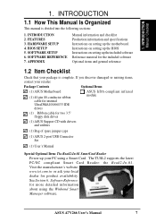
SOFTWARE SETUP 6. ASUS A7V266 User's Manual 7 INTRODUCTION Manual / Checklist 1. INTRODUCTION 2. If you discover damaged or missing items, contact your local dealer for the included software Optional ...and specifications Instructions on setting up the included software Reference material for product availability. Package Contents Optional Items (1) ASUS Motherboard (1) 40-pin 80-conductor ribbon cable for internal UltraDMA100/66//33 IDE drives ASUS IrDA-compliant infrared module (1) Ribbon cable for more detailed information about using a Smart Card. Instructions on ...
SOFTWARE SETUP 6. ASUS A7V266 User's Manual 7 INTRODUCTION Manual / Checklist 1. INTRODUCTION 2. If you discover damaged or missing items, contact your local dealer for the included software Optional ...and specifications Instructions on setting up the included software Reference material for product availability. Package Contents Optional Items (1) ASUS Motherboard (1) 40-pin 80-conductor ribbon cable for internal UltraDMA100/66//33 IDE drives ASUS IrDA-compliant infrared module (1) Ribbon cable for more detailed information about using a Smart Card. Instructions on ...

Motherboard DIY Troubleshooting Guide
Page 8
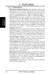
FEATURES 2.1 ASUS A7V266 Motherboard The ASUS A7V266 motherboard is targeted diversely for six USB ports. • PC2100 / PC1600 DDR Support: Equipped with today's demand for a flexible high-integration system. 2.1.1 Specifications • AMD® ... complies with three Double Data Rate Dual Inline Memory Module (DDR DIMM) sockets to support up to physically transport commands and information between SMBus devices. 8 ASUS A7V266 User's Manual Easy-to-use SDRAM modules.) • JumperFree™ Mode: Allows processor settings and easy overclocking of up to 3GB of DDR DRAM. ...
FEATURES 2.1 ASUS A7V266 Motherboard The ASUS A7V266 motherboard is targeted diversely for six USB ports. • PC2100 / PC1600 DDR Support: Equipped with today's demand for a flexible high-integration system. 2.1.1 Specifications • AMD® ... complies with three Double Data Rate Dual Inline Memory Module (DDR DIMM) sockets to support up to physically transport commands and information between SMBus devices. 8 ASUS A7V266 User's Manual Easy-to-use SDRAM modules.) • JumperFree™ Mode: Allows processor settings and easy overclocking of up to 3GB of DDR DRAM. ...

Motherboard DIY Troubleshooting Guide
Page 9
..., an easy-to-access box with EPP and ECP capabilities. The ACR is any standby power on the motherboard accommodates the ASUS iPanel. ASUS A7V266 User's Manual 9 The ACR specification supports modem, audio and LAN technologies. FEATURES Specifications 2. FEATURES • PCI Expansion Slots: Five 32-bit PCI (Rev...cards, like SCSI or LAN cards, with the Audio Modem Riser (AMR). • Wake-On-LAN: Supports Wake-On-LAN activity through an optional ASUS PCI-L101 10 /100 Fast Ethernet PCI card. • Wake-On-Ring: Supports Wake-On-Ring activity through a PCI modem card. • ...
..., an easy-to-access box with EPP and ECP capabilities. The ACR is any standby power on the motherboard accommodates the ASUS iPanel. ASUS A7V266 User's Manual 9 The ACR specification supports modem, audio and LAN technologies. FEATURES Specifications 2. FEATURES • PCI Expansion Slots: Five 32-bit PCI (Rev...cards, like SCSI or LAN cards, with the Audio Modem Riser (AMR). • Wake-On-LAN: Supports Wake-On-LAN activity through an optional ASUS PCI-L101 10 /100 Fast Ethernet PCI card. • Wake-On-Ring: Supports Wake-On-Ring activity through a PCI modem card. • ...
Motherboard DIY Troubleshooting Guide
Page 10
...; High-Speed Data Transfer Interface: Support for Windows95/98/NT . The chip supports software access to the memory and processor. 10 ASUS A7V266 User's Manual Color-coded connectors and descriptive icons make identification easy as Windows 98. • Smartcard Reader Connector: Features a connector ... DVD playback, PCtel 56K modem, and even Karaoke echo effects. With these features employed in data transfer rates of ASUS smart series motherboards are based on the following high-level goals: Support for Plugn-Play compatibility and power management for configuring and managing all...
...; High-Speed Data Transfer Interface: Support for Windows95/98/NT . The chip supports software access to the memory and processor. 10 ASUS A7V266 User's Manual Color-coded connectors and descriptive icons make identification easy as Windows 98. • Smartcard Reader Connector: Features a connector ... DVD playback, PCtel 56K modem, and even Karaoke echo effects. With these features employed in data transfer rates of ASUS smart series motherboards are based on the following high-level goals: Support for Plugn-Play compatibility and power management for configuring and managing all...

Motherboard DIY Troubleshooting Guide
Page 11
...this benefit on-hand, users can be turned on battery power for future processors, so monitoring is kept in 4.5 Power Menu). ASUS A7V266 User's Manual 11 When the power button is pressed for more protection. A chassis intrusion event is necessary to be monitored for... < 4 Secs in memory on remotely through the ASUS ASIC. Voltage specifications are more critical for more than 4 seconds when the system is monitored by the ASUS ASIC through the CPU's internal thermal diode (on Pentium III and Celeron) to critical motherboard components. 2. FEATURES Intelligence 2.
...this benefit on-hand, users can be turned on battery power for future processors, so monitoring is kept in 4.5 Power Menu). ASUS A7V266 User's Manual 11 When the power button is pressed for more protection. A chassis intrusion event is necessary to be monitored for... < 4 Secs in memory on remotely through the ASUS ASIC. Voltage specifications are more critical for more than 4 seconds when the system is monitored by the ASUS ASIC through the CPU's internal thermal diode (on Pentium III and Celeron) to critical motherboard components. 2. FEATURES Intelligence 2.

Motherboard DIY Troubleshooting Guide
Page 12
...Motherboard Components See opposite page for AMD® Athlon™ and Duron™ Processors 2 Feature Setting DIP Switches 3 Chipsets VIA® VT8366 North Bridge 1 VIA® VT8233 South Bridge 9 ASUS... Disk Drive Connector 10 2 IDE Connectors (UltraDMA/100 Support 6 1 ASUS iPanel Connector 8 1 Parallel Port Top) 23 2 Serial Ports (COM1...Connector Bottom) 26 Hardware Monitoring System Voltage Monitoring (integrated in ASUS ASIC) ......... 7 3 Fan Power and Speed Monitoring Connectors...only) CMI8738 6-Channel Audio Controller 13 1 ASUS iPanel Audio Connector 14 1 Game/MIDI ...
...Motherboard Components See opposite page for AMD® Athlon™ and Duron™ Processors 2 Feature Setting DIP Switches 3 Chipsets VIA® VT8366 North Bridge 1 VIA® VT8233 South Bridge 9 ASUS... Disk Drive Connector 10 2 IDE Connectors (UltraDMA/100 Support 6 1 ASUS iPanel Connector 8 1 Parallel Port Top) 23 2 Serial Ports (COM1...Connector Bottom) 26 Hardware Monitoring System Voltage Monitoring (integrated in ASUS ASIC) ......... 7 3 Fan Power and Speed Monitoring Connectors...only) CMI8738 6-Channel Audio Controller 13 1 ASUS iPanel Audio Connector 14 1 Game/MIDI ...

Motherboard DIY Troubleshooting Guide
Page 13
FEATURES Motherboard Parts 2. 2. FEATURES 2.2.1 Component Locations 1 23 4 56 26 25 24 23 22 21 20 19 18 17 16 15 14 13 12 11 10 9 8 7 ASUS A7V266 User's Manual 13
FEATURES Motherboard Parts 2. 2. FEATURES 2.2.1 Component Locations 1 23 4 56 26 25 24 23 22 21 20 19 18 17 16 15 14 13 12 11 10 9 8 7 ASUS A7V266 User's Manual 13

Motherboard DIY Troubleshooting Guide
Page 14
.../72 bit, 184-pin module) ATX Power Connector Primary IDE Secondary IDE 30.5cm (12.0in) Socket 462 3. H/W SETUP Motherboard Layout 3. HARDWARE SETUP 3.1 Motherboard Layout PS/2 T: Mouse B: Keyboard KBWK USB1 USB2 USB01_PWR COM1 01 01 01 24.5cm (9.64in) DSW CPU_RATIO VID4 VID3 VID2...AGP Pro) PCI 1 DSW SYSCLK PCI 2 SMARTCARD PCI 3 CD PCI 4 PCI 5 ACR A7V266 VIA VT8233 Chipset CR2032 3V Lithium Cell CMOS Power ACRUSB SMB_CON JTPWR CLR_RTC ASUS FLOPPY ASIC with Hardware JEN Monitor CHA_FAN CHASSIS CHA IR_CON USB45_PWR IDELED USB23_PWR USB2_3 USB4_5 AFPANEL PANEL ...
.../72 bit, 184-pin module) ATX Power Connector Primary IDE Secondary IDE 30.5cm (12.0in) Socket 462 3. H/W SETUP Motherboard Layout 3. HARDWARE SETUP 3.1 Motherboard Layout PS/2 T: Mouse B: Keyboard KBWK USB1 USB2 USB01_PWR COM1 01 01 01 24.5cm (9.64in) DSW CPU_RATIO VID4 VID3 VID2...AGP Pro) PCI 1 DSW SYSCLK PCI 2 SMARTCARD PCI 3 CD PCI 4 PCI 5 ACR A7V266 VIA VT8233 Chipset CR2032 3V Lithium Cell CMOS Power ACRUSB SMB_CON JTPWR CLR_RTC ASUS FLOPPY ASIC with Hardware JEN Monitor CHA_FAN CHASSIS CHA IR_CON USB45_PWR IDELED USB23_PWR USB2_3 USB4_5 AFPANEL PANEL ...

Motherboard DIY Troubleshooting Guide
Page 15
3. HARDWARE SETUP 3.2 Layout Contents Motherboard Settings 1) JEN p. 18 JumperFree Mode Setting (Disable / Enable) 2) DIP_SW p. 19 CPU External Frequency Selection (Switches 1-4) 3) DSW p. 20 Manual CPU Ratio Settings (Switches 1-5) 4) PALO_FREQ p. 20 FID ... (15-pin female) (optional) 7) AUDIO p. 35 Audio Connectors (Three 1/8" AUDIO) (optional) 8) IDELED p. 36 IDE Activity LED (2 pin) 9) FLOPPY p. 36 Floppy Disk Drive Connector (34 pin) ASUS A7V266 User's Manual 15 H/W SETUP Layout Contents 3.
3. HARDWARE SETUP 3.2 Layout Contents Motherboard Settings 1) JEN p. 18 JumperFree Mode Setting (Disable / Enable) 2) DIP_SW p. 19 CPU External Frequency Selection (Switches 1-4) 3) DSW p. 20 Manual CPU Ratio Settings (Switches 1-5) 4) PALO_FREQ p. 20 FID ... (15-pin female) (optional) 7) AUDIO p. 35 Audio Connectors (Three 1/8" AUDIO) (optional) 8) IDELED p. 36 IDE Activity LED (2 pin) 9) FLOPPY p. 36 Floppy Disk Drive Connector (34 pin) ASUS A7V266 User's Manual 15 H/W SETUP Layout Contents 3.

Motherboard DIY Troubleshooting Guide
Page 17
... suspend or soft-off mode, not powered OFF. H/W SETUP Motherboard Settings 01 01 01 A7V266 A7V266 Onboard LED LED ON Standby Power OFF Powered Off ASUS A7V266 User's Manual 17 Connect ribbon cables, panel wires, and power supply cables 6. See illustration below.) 3. Check motherboard settings 2. Computer motherboards and expansion cards contain very delicate Integrated Circuit (IC) chips...
... suspend or soft-off mode, not powered OFF. H/W SETUP Motherboard Settings 01 01 01 A7V266 A7V266 Onboard LED LED ON Standby Power OFF Powered Off ASUS A7V266 User's Manual 17 Connect ribbon cables, panel wires, and power supply cables 6. See illustration below.) 3. Check motherboard settings 2. Computer motherboards and expansion cards contain very delicate Integrated Circuit (IC) chips...

Motherboard DIY Troubleshooting Guide
Page 18
... illustration below shows all DIP switches (DIP_SW) to OFF. 18 ASUS A7V266 User's Manual 3. HARDWARE SETUP Motherboard Frequency Settings (DIP Switches) The motherboard frequency is adjusted through the BIOS setup (see 4.4 Advanced Menu). Setting JEN Enable (JumperFree) [2-3] (default) Disable (Jumper Mode) [1-2] JEN CPU_RATIO A7V266 ON ON 12345 OFF SYSCLK ON 1234 ON OFF 12 23...
... illustration below shows all DIP switches (DIP_SW) to OFF. 18 ASUS A7V266 User's Manual 3. HARDWARE SETUP Motherboard Frequency Settings (DIP Switches) The motherboard frequency is adjusted through the BIOS setup (see 4.4 Advanced Menu). Setting JEN Enable (JumperFree) [2-3] (default) Disable (Jumper Mode) [1-2] JEN CPU_RATIO A7V266 ON ON 12345 OFF SYSCLK ON 1234 ON OFF 12 23...

Motherboard DIY Troubleshooting Guide
Page 19
IMPORTANT: 1. H/W SETUP Motherboard Settings 01 01 01 01 01 01 SYSCLK ON 1234 ON 1234 ON 1234 ON 1234 CPU 100MHz 133.33MHz 140MHz AGP 60.67MHz 66.67MHz 70MHz (JumperFree Mode) A7V266 PCI 33.33MHz 33.33MHz 35MHz A7V266 CPU External Frequency Selection WARNING! Set the CPU ... ON ON 12345 CPU_RATIO 8X ON 12345 8.5X ON 12345 9X ON 12345 9.5X 12345 12345 12345 A7V266 CPU_RATIO 10X 10.5X (JumperFree Mode) A7V266 CPU External Clock (BUS) Frequency Selection ASUS A7V266 User's Manual 19 This allows the selection of your processor and the bus frequency (133/100MHz).
IMPORTANT: 1. H/W SETUP Motherboard Settings 01 01 01 01 01 01 SYSCLK ON 1234 ON 1234 ON 1234 ON 1234 CPU 100MHz 133.33MHz 140MHz AGP 60.67MHz 66.67MHz 70MHz (JumperFree Mode) A7V266 PCI 33.33MHz 33.33MHz 35MHz A7V266 CPU External Frequency Selection WARNING! Set the CPU ... ON ON 12345 CPU_RATIO 8X ON 12345 8.5X ON 12345 9X ON 12345 9.5X 12345 12345 12345 A7V266 CPU_RATIO 10X 10.5X (JumperFree Mode) A7V266 CPU External Clock (BUS) Frequency Selection ASUS A7V266 User's Manual 19 This allows the selection of your processor and the bus frequency (133/100MHz).

Motherboard DIY Troubleshooting Guide
Page 20
... between the internal frequency between standard and new AMD CPUs. A7V266 A7V266 Voltage Setting JP1/JP2 12 3 JP1 JP2 12 3 12 3 2.5V 2.65V 2.75V (Default) 12 3 2.8V 20 ASUS A7V266 User's Manual H/W SETUP Motherboard Settings 3. PALO_FREQ FID0 FID1 FID2 FID3 123 123 FID0 FID1... FID2 FID3 PALOMINO ATHLON/DURON A7V266 (Default) A7V266 PALO_FREQ Setting 01 01 01 01 01 01 5) I/O Voltage Settings (JP1, JP2)...
... between the internal frequency between standard and new AMD CPUs. A7V266 A7V266 Voltage Setting JP1/JP2 12 3 JP1 JP2 12 3 12 3 2.5V 2.65V 2.75V (Default) 12 3 2.8V 20 ASUS A7V266 User's Manual H/W SETUP Motherboard Settings 3. PALO_FREQ FID0 FID1 FID2 FID3 123 123 FID0 FID1... FID2 FID3 PALOMINO ATHLON/DURON A7V266 (Default) A7V266 PALO_FREQ Setting 01 01 01 01 01 01 5) I/O Voltage Settings (JP1, JP2)...

Motherboard DIY Troubleshooting Guide
Page 21
...Setting (VID1, VID2, VID3, VID4) This jumpers allow you to the CPU VID configuration. A7V266 A7V266 Bass Center Setting BCS 12 23 type 1 Bass (CENTER/BASS) (Default) type 2 Bass (BASS/CENTER) ASUS A7V266 User's Manual 21 It is made using the C-Media Audio Driver software setup available on ...voltage. No audio standard exists for 4 or 6 speaker audio. H/W SETUP Motherboard Settings 01 01 01 01 01 01 3. For each jumper setting, there are two voltage options, depending on the Support CD. A7V266 A7V266 CPU Core Voltage Selection 123 VID4 VID3 VID2 VID1 1.85/1.825Volts 123 1.8/1....
...Setting (VID1, VID2, VID3, VID4) This jumpers allow you to the CPU VID configuration. A7V266 A7V266 Bass Center Setting BCS 12 23 type 1 Bass (CENTER/BASS) (Default) type 2 Bass (BASS/CENTER) ASUS A7V266 User's Manual 21 It is made using the C-Media Audio Driver software setup available on ...voltage. No audio standard exists for 4 or 6 speaker audio. H/W SETUP Motherboard Settings 01 01 01 01 01 01 3. For each jumper setting, there are two voltage options, depending on the Support CD. A7V266 A7V266 CPU Core Voltage Selection 123 VID4 VID3 VID2 VID1 1.85/1.825Volts 123 1.8/1....

Motherboard DIY Troubleshooting Guide
Page 22
... selecting a device. 3. This feature requires an ATX power supply that can supply at least 300mA on ACR 22 ASUS A7V266 User's Manual H/W SETUP Motherboard Settings A7V266 A7V266 USB/ACR Selection ACRUSB 12 23 USB to pins 2-3 activates the Advanced Communication Riser (ACR) slot. The default ...the jumpers to Conn. USB on the +5VSB lead. Setting Enable Disable KBWK [1-2] (default) [2-3] KBWK 12 Enable (Default) 23 Disable A7V266 A7V266 Keyboard Wake Up 9) ACR/USB Selection (ACRUSB1, ACRUSB2) (audio models only) When set in conjunction with Wake On PS2 KB/PS2 Mouse/...
... selecting a device. 3. This feature requires an ATX power supply that can supply at least 300mA on ACR 22 ASUS A7V266 User's Manual H/W SETUP Motherboard Settings A7V266 A7V266 USB/ACR Selection ACRUSB 12 23 USB to pins 2-3 activates the Advanced Communication Riser (ACR) slot. The default ...the jumpers to Conn. USB on the +5VSB lead. Setting Enable Disable KBWK [1-2] (default) [2-3] KBWK 12 Enable (Default) 23 Disable A7V266 A7V266 Keyboard Wake Up 9) ACR/USB Selection (ACRUSB1, ACRUSB2) (audio models only) When set in conjunction with Wake On PS2 KB/PS2 Mouse/...

Motherboard DIY Troubleshooting Guide
Page 23
... to select +5V (because not all computers have the appropriate power supply). power supply in sleep mode. 01 01 01 12 23 USB01_PWR +5V +5VSB A7V266 A7V266 USB Device Wake Up 12 23 USB23_PWR USB45_PWR +5V +5VSB 3. The default setting for the three jumpers is 1-2 to allow wake up from S3 sleep...) Set these jumpers are set to CPU; HARDWARE SETUP 10) USB Device Wake-up . 2. RAM in low power mode) using the connected USB devices. H/W SETUP Motherboard Settings ASUS A7V266 User's Manual 23 RAM refreshed;
... to select +5V (because not all computers have the appropriate power supply). power supply in sleep mode. 01 01 01 12 23 USB01_PWR +5V +5VSB A7V266 A7V266 USB Device Wake Up 12 23 USB23_PWR USB45_PWR +5V +5VSB 3. The default setting for the three jumpers is 1-2 to allow wake up from S3 sleep...) Set these jumpers are set to CPU; HARDWARE SETUP 10) USB Device Wake-up . 2. RAM in low power mode) using the connected USB devices. H/W SETUP Motherboard Settings ASUS A7V266 User's Manual 23 RAM refreshed;

Motherboard DIY Troubleshooting Guide
Page 24
...powered by the onboard button cell battery. To erase the RTC RAM: 1. Turn OFF the computer and unplug the power cord. 2. H/W SETUP Motherboard Settings A7V266 A7V266 Clear RTC RAM CR2032 3V Lithium Cell CMOS Power CLRTC Remove and then replace the jumper cap. 12) Thermal Sensor CPU Setting (2-pin THEMCPU) This... power cord and turn ON the computer. 6. The default setting, [1-2], is for Reserve type processors. 3. THEMCPU 12 23 ATHLON/DURON (Default) RESERVED A7V266 A7V266 THEMCPU Setting 24 ASUS A7V266 User's Manual Short the jumper by erasing the CMOS RTC RAM data.
...powered by the onboard button cell battery. To erase the RTC RAM: 1. Turn OFF the computer and unplug the power cord. 2. H/W SETUP Motherboard Settings A7V266 A7V266 Clear RTC RAM CR2032 3V Lithium Cell CMOS Power CLRTC Remove and then replace the jumper cap. 12) Thermal Sensor CPU Setting (2-pin THEMCPU) This... power cord and turn ON the computer. 6. The default setting, [1-2], is for Reserve type processors. 3. THEMCPU 12 23 ATHLON/DURON (Default) RESERVED A7V266 A7V266 THEMCPU Setting 24 ASUS A7V266 User's Manual Short the jumper by erasing the CMOS RTC RAM data.

Motherboard DIY Troubleshooting Guide
Page 25
HARDWARE SETUP 3.5 System Memory This motherboard features three Double Data Rate (DDR) Dual Inline Memory Module sockets. 3.5.1 DDR DIMM Support The two DDR DIMM sockets support 2.5Volt (power level) unbuffered/registered ... one row on desktops/laptops). DDR DIMMs support non-ECC memory (used on the motherboard. One side (with memory chips) of 64MB, 128MB, 256MB, 512MB, and 1GB to form a memory size between 64MB to 3GB. H/W SETUP System Memory ASUS A7V266 User's Manual 25 Install memory in any combination as follows: DIMM Location Socket...
HARDWARE SETUP 3.5 System Memory This motherboard features three Double Data Rate (DDR) Dual Inline Memory Module sockets. 3.5.1 DDR DIMM Support The two DDR DIMM sockets support 2.5Volt (power level) unbuffered/registered ... one row on desktops/laptops). DDR DIMMs support non-ECC memory (used on the motherboard. One side (with memory chips) of 64MB, 128MB, 256MB, 512MB, and 1GB to form a memory size between 64MB to 3GB. H/W SETUP System Memory ASUS A7V266 User's Manual 25 Install memory in any combination as follows: DIMM Location Socket...


