Motherboard DIY Troubleshooting Guide
Page 1
® A7V266 JumperFree™ DDR DRAM 266MHz FSB AGP Pro/4X Socket A Motherboard USER'S MANUAL
® A7V266 JumperFree™ DDR DRAM 266MHz FSB AGP Pro/4X Socket A Motherboard USER'S MANUAL

Motherboard DIY Troubleshooting Guide
Page 4
... 14 3.2 Layout Contents 15 3.3 Hardware Setup Procedure 17 3.4 Motherboard Settings 17 3.5 System Memory 25 3.5.1 DDR DIMM Support 25 3.5.1 General DIMM Notes 26 3.5.2 Memory Installation 26 3.6... Updating BIOS Procedures 47 4.2 BIOS Setup Program 49 4.2.1 BIOS Menu Bar 50 4.2.2 Legend Bar 50 4 ASUS A7V266 User's Manual INTRODUCTION 7 1.1 How This Manual Is Organized 7 1.2 Item Checklist 7 2. CONTENTS 1. FEATURES 8 2.1 ASUS A7V266 Motherboard 8 2.1.1 Specifications 8 2.1.2 Performance 10 2.1.3 Intelligence 11 2.2 Motherboard Components 12 2.2.1 Component Locations 13 3.
... 14 3.2 Layout Contents 15 3.3 Hardware Setup Procedure 17 3.4 Motherboard Settings 17 3.5 System Memory 25 3.5.1 DDR DIMM Support 25 3.5.1 General DIMM Notes 26 3.5.2 Memory Installation 26 3.6... Updating BIOS Procedures 47 4.2 BIOS Setup Program 49 4.2.1 BIOS Menu Bar 50 4.2.2 Legend Bar 50 4 ASUS A7V266 User's Manual INTRODUCTION 7 1.1 How This Manual Is Organized 7 1.2 Item Checklist 7 2. CONTENTS 1. FEATURES 8 2.1 ASUS A7V266 Motherboard 8 2.1.1 Specifications 8 2.1.2 Performance 10 2.1.3 Intelligence 11 2.2 Motherboard Components 12 2.2.1 Component Locations 13 3.
Motherboard DIY Troubleshooting Guide
Page 7
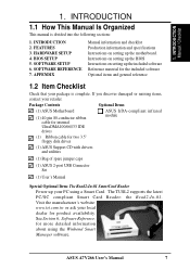
... Connector Set (1) User's Manual Special Optional Item: The Read2-In-01 SmartCard Reader Power up the motherboard. ASUS A7V266 User's Manual 7 Visit the manufacturer's website: www.tzt.com.tw or ask your retailer. INTRODUCTION Manual / Checklist 1. Package Contents Optional Items (1) ASUS Motherboard (1) 40-pin 80-conductor ribbon cable for internal UltraDMA100/66//33 IDE drives...
... Connector Set (1) User's Manual Special Optional Item: The Read2-In-01 SmartCard Reader Power up the motherboard. ASUS A7V266 User's Manual 7 Visit the manufacturer's website: www.tzt.com.tw or ask your retailer. INTRODUCTION Manual / Checklist 1. Package Contents Optional Items (1) ASUS Motherboard (1) 40-pin 80-conductor ribbon cable for internal UltraDMA100/66//33 IDE drives...

Motherboard DIY Troubleshooting Guide
Page 8
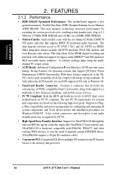
... the VIA® VT8366 North Bridge that supports high performance AGP cards targeted at 3D graphical applications supporting 133MHz 4X mode. FEATURES Specifications 2. FEATURES 2.1 ASUS A7V266 Motherboard The ASUS A7V266 motherboard is targeted diversely for six USB ports. • PC2100 / PC1600 DDR Support: Equipped with three root hubs for home PCs, workstations and servers. Supports...with three Double Data Rate Dual Inline Memory Module (DDR DIMM) sockets to support up to physically transport commands and information between SMBus devices. 8 ASUS A7V266 User's Manual
... the VIA® VT8366 North Bridge that supports high performance AGP cards targeted at 3D graphical applications supporting 133MHz 4X mode. FEATURES Specifications 2. FEATURES 2.1 ASUS A7V266 Motherboard The ASUS A7V266 motherboard is targeted diversely for six USB ports. • PC2100 / PC1600 DDR Support: Equipped with three root hubs for home PCs, workstations and servers. Supports...with three Double Data Rate Dual Inline Memory Module (DDR DIMM) sockets to support up to physically transport commands and information between SMBus devices. 8 ASUS A7V266 User's Manual

Motherboard DIY Troubleshooting Guide
Page 9
... Slots: Five 32-bit PCI (Rev. 2.2) expansion slots that lights up if there is any standby power on the motherboard accommodates the ASUS iPanel. The ACR specification supports modem, audio and LAN technologies. ASUS A7V266 User's Manual 9 This LED acts as a reminder to turn off the system power before plugging or unplugging devices to...
... Slots: Five 32-bit PCI (Rev. 2.2) expansion slots that lights up if there is any standby power on the motherboard accommodates the ASUS iPanel. The ACR specification supports modem, audio and LAN technologies. ASUS A7V266 User's Manual 9 This LED acts as a reminder to turn off the system power before plugging or unplugging devices to...
Motherboard DIY Troubleshooting Guide
Page 10
...icons make identification easy as Windows 98. • Smartcard Reader Connector: Features a connector that provides the convenience of ASUS smart series motherboards are based on the following high-level goals: Support for Plugn-Play compatibility and power management for configuring and managing ...conductor cable). • Concurrent PCI: Concurrent PCI allows multiple PCI transfers from PCI master busses to the memory and processor. 10 ASUS A7V266 User's Manual The chip offers 24-bit SPDIF digital recording and playback with additional support for Windows95/98/NT . 2. A ...
...icons make identification easy as Windows 98. • Smartcard Reader Connector: Features a connector that provides the convenience of ASUS smart series motherboards are based on the following high-level goals: Support for Plugn-Play compatibility and power management for configuring and managing ...conductor cable). • Concurrent PCI: Concurrent PCI allows multiple PCI transfers from PCI master busses to the memory and processor. 10 ASUS A7V266 User's Manual The chip offers 24-bit SPDIF digital recording and playback with additional support for Windows95/98/NT . 2. A ...

Motherboard DIY Troubleshooting Guide
Page 11
ASUS A7V266 User's Manual 11 When the power button is pressed for more...for more critical for future processors, so monitoring is monitored by the ASUS ASIC through the CPU's internal thermal diode (on remotely through the ASUS ASIC. With this benefit on-hand, users can be turned on ...Pentium III and Celeron) to prevent system overheat and system damage. • Voltage Monitoring and Alert: System voltage levels are set for RPM and failure. All fans are monitored to ensure stable voltage to critical motherboard...
ASUS A7V266 User's Manual 11 When the power button is pressed for more...for more critical for future processors, so monitoring is monitored by the ASUS ASIC through the CPU's internal thermal diode (on remotely through the ASUS ASIC. With this benefit on-hand, users can be turned on ...Pentium III and Celeron) to prevent system overheat and system damage. • Voltage Monitoring and Alert: System voltage levels are set for RPM and failure. All fans are monitored to ensure stable voltage to critical motherboard...

Motherboard DIY Troubleshooting Guide
Page 12
FEATURES 2.2 Motherboard Components See opposite page for AMD® Athlon™ and Duron™ Processors 2 Feature Setting DIP Switches 3 Chipsets VIA® VT8366 North Bridge 1 VIA® VT8233 South Bridge 9 ASUS System Monitor controller 7 C-Media® 6 Channel CMI8738 PCI audio ... 13 1 ASUS iPanel Audio Connector 14 1 Game/MIDI Port Top) 21 1 Line Out Connector Bottom, left) 21 1 Line In Connector Bottom, center) 21 1 Microphone Connector Bottom, right) 21 Internal Audio Connectors Power ATX Power Supply Connector 5 Form Factor ATX 12 ASUS A7V266 User's Manual...
FEATURES 2.2 Motherboard Components See opposite page for AMD® Athlon™ and Duron™ Processors 2 Feature Setting DIP Switches 3 Chipsets VIA® VT8366 North Bridge 1 VIA® VT8233 South Bridge 9 ASUS System Monitor controller 7 C-Media® 6 Channel CMI8738 PCI audio ... 13 1 ASUS iPanel Audio Connector 14 1 Game/MIDI Port Top) 21 1 Line Out Connector Bottom, left) 21 1 Line In Connector Bottom, center) 21 1 Microphone Connector Bottom, right) 21 Internal Audio Connectors Power ATX Power Supply Connector 5 Form Factor ATX 12 ASUS A7V266 User's Manual...

Motherboard DIY Troubleshooting Guide
Page 13
2. FEATURES 2.2.1 Component Locations 1 23 4 56 26 25 24 23 22 21 20 19 18 17 16 15 14 13 12 11 10 9 8 7 ASUS A7V266 User's Manual 13 FEATURES Motherboard Parts 2.
2. FEATURES 2.2.1 Component Locations 1 23 4 56 26 25 24 23 22 21 20 19 18 17 16 15 14 13 12 11 10 9 8 7 ASUS A7V266 User's Manual 13 FEATURES Motherboard Parts 2.

Motherboard DIY Troubleshooting Guide
Page 14
... (64/72 bit, 184-pin module) ATX Power Connector Primary IDE Secondary IDE 30.5cm (12.0in) Socket 462 3. HARDWARE SETUP 3.1 Motherboard Layout PS/2 T: Mouse B: Keyboard KBWK USB1 USB2 USB01_PWR COM1 01 01 01 24.5cm (9.64in) DSW CPU_RATIO VID4 VID3 VID2 VID1 PALO_FREQ THEMCPU... Port (AGP Pro) PCI 1 DSW SYSCLK PCI 2 SMARTCARD PCI 3 CD PCI 4 PCI 5 ACR A7V266 VIA VT8233 Chipset CR2032 3V Lithium Cell CMOS Power ACRUSB SMB_CON JTPWR CLR_RTC ASUS FLOPPY ASIC with Hardware JEN Monitor CHA_FAN CHASSIS CHA IR_CON USB45_PWR IDELED USB23_PWR USB2_3 USB4_5 AFPANEL PANEL 14...
... (64/72 bit, 184-pin module) ATX Power Connector Primary IDE Secondary IDE 30.5cm (12.0in) Socket 462 3. HARDWARE SETUP 3.1 Motherboard Layout PS/2 T: Mouse B: Keyboard KBWK USB1 USB2 USB01_PWR COM1 01 01 01 24.5cm (9.64in) DSW CPU_RATIO VID4 VID3 VID2 VID1 PALO_FREQ THEMCPU... Port (AGP Pro) PCI 1 DSW SYSCLK PCI 2 SMARTCARD PCI 3 CD PCI 4 PCI 5 ACR A7V266 VIA VT8233 Chipset CR2032 3V Lithium Cell CMOS Power ACRUSB SMB_CON JTPWR CLR_RTC ASUS FLOPPY ASIC with Hardware JEN Monitor CHA_FAN CHASSIS CHA IR_CON USB45_PWR IDELED USB23_PWR USB2_3 USB4_5 AFPANEL PANEL 14...

Motherboard DIY Troubleshooting Guide
Page 15
HARDWARE SETUP 3.2 Layout Contents Motherboard Settings 1) JEN p. 18 JumperFree Mode Setting (Disable / Enable) 2) DIP_SW p. 19 CPU External Frequency Selection (Switches 1-4) 3) DSW p. 20 Manual CPU Ratio Settings (Switches 1-5) 4) PALO_FREQ p. 20 FID ... (15-pin female) (optional) 7) AUDIO p. 35 Audio Connectors (Three 1/8" AUDIO) (optional) 8) IDELED p. 36 IDE Activity LED (2 pin) 9) FLOPPY p. 36 Floppy Disk Drive Connector (34 pin) ASUS A7V266 User's Manual 15 3.
HARDWARE SETUP 3.2 Layout Contents Motherboard Settings 1) JEN p. 18 JumperFree Mode Setting (Disable / Enable) 2) DIP_SW p. 19 CPU External Frequency Selection (Switches 1-4) 3) DSW p. 20 Manual CPU Ratio Settings (Switches 1-5) 4) PALO_FREQ p. 20 FID ... (15-pin female) (optional) 7) AUDIO p. 35 Audio Connectors (Three 1/8" AUDIO) (optional) 8) IDELED p. 36 IDE Activity LED (2 pin) 9) FLOPPY p. 36 Floppy Disk Drive Connector (34 pin) ASUS A7V266 User's Manual 15 3.

Motherboard DIY Troubleshooting Guide
Page 17
... tells you install or remove any component, place the components on your computer: 1. To avoid damaging them . 4. H/W SETUP Motherboard Settings 01 01 01 A7V266 A7V266 Onboard LED LED ON Standby Power OFF Powered Off ASUS A7V266 User's Manual 17 HARDWARE SETUP 3.3 Hardware Setup Procedure Complete the following steps before handling computer components. 3. Whenever you work...
... tells you install or remove any component, place the components on your computer: 1. To avoid damaging them . 4. H/W SETUP Motherboard Settings 01 01 01 A7V266 A7V266 Onboard LED LED ON Standby Power OFF Powered Off ASUS A7V266 User's Manual 17 HARDWARE SETUP 3.3 Hardware Setup Procedure Complete the following steps before handling computer components. 3. Whenever you work...

Motherboard DIY Troubleshooting Guide
Page 18
... 01 01 3. The illustration below shows all DIP switches (DIP_SW) to OFF. 18 ASUS A7V266 User's Manual The JumperFree™ mode allows processor settings to enable or disable the JumperFree™ mode. HARDWARE SETUP Motherboard Frequency Settings (DIP Switches) The motherboard frequency is adjusted through the BIOS setup (see 4.4 Advanced Menu). The white block...
... 01 01 3. The illustration below shows all DIP switches (DIP_SW) to OFF. 18 ASUS A7V266 User's Manual The JumperFree™ mode allows processor settings to enable or disable the JumperFree™ mode. HARDWARE SETUP Motherboard Frequency Settings (DIP Switches) The motherboard frequency is adjusted through the BIOS setup (see 4.4 Advanced Menu). The white block...

Motherboard DIY Troubleshooting Guide
Page 19
... allows the selection of your processor and the bus frequency (133/100MHz). To use this feature, JEN must be stable. 3. H/W SETUP Motherboard Settings 01 01 01 01 01 01 SYSCLK ON 1234 ON 1234 ON 1234 ON 1234 CPU 100MHz 133.33MHz 140MHz AGP 60.67MHz 66....ON ON ON ON 12345 CPU_RATIO 8X ON 12345 8.5X ON 12345 9X ON 12345 9.5X 12345 12345 12345 A7V266 CPU_RATIO 10X 10.5X (JumperFree Mode) A7V266 CPU External Clock (BUS) Frequency Selection ASUS A7V266 User's Manual 19 The BUS Clock multiplied by the Frequency Multiple equals the CPU's Internal frequency (the advertised CPU...
... allows the selection of your processor and the bus frequency (133/100MHz). To use this feature, JEN must be stable. 3. H/W SETUP Motherboard Settings 01 01 01 01 01 01 SYSCLK ON 1234 ON 1234 ON 1234 ON 1234 CPU 100MHz 133.33MHz 140MHz AGP 60.67MHz 66....ON ON ON ON 12345 CPU_RATIO 8X ON 12345 8.5X ON 12345 9X ON 12345 9.5X 12345 12345 12345 A7V266 CPU_RATIO 10X 10.5X (JumperFree Mode) A7V266 CPU External Clock (BUS) Frequency Selection ASUS A7V266 User's Manual 19 The BUS Clock multiplied by the Frequency Multiple equals the CPU's Internal frequency (the advertised CPU...

Motherboard DIY Troubleshooting Guide
Page 20
...the difference between the internal frequency between standard and new AMD CPUs. H/W SETUP Motherboard Settings 3. PALO_FREQ FID0 FID1 FID2 FID3 123 123 FID0 FID1 FID2 FID3 PALOMINO ATHLON/DURON A7V266 (Default) A7V266 PALO_FREQ Setting 01 01 01 01 01 01 5) I/O Voltage Settings (JP1, ... to another, the jumper caps must be adjusted. A7V266 A7V266 Voltage Setting JP1/JP2 12 3 JP1 JP2 12 3 12 3 2.5V 2.65V 2.75V (Default) 12 3 2.8V 20 ASUS A7V266 User's Manual The Palomino processor will only function on this motherboard after the jumpers are adjusted to [1-2].
...the difference between the internal frequency between standard and new AMD CPUs. H/W SETUP Motherboard Settings 3. PALO_FREQ FID0 FID1 FID2 FID3 123 123 FID0 FID1 FID2 FID3 PALOMINO ATHLON/DURON A7V266 (Default) A7V266 PALO_FREQ Setting 01 01 01 01 01 01 5) I/O Voltage Settings (JP1, ... to another, the jumper caps must be adjusted. A7V266 A7V266 Voltage Setting JP1/JP2 12 3 JP1 JP2 12 3 12 3 2.5V 2.65V 2.75V (Default) 12 3 2.8V 20 ASUS A7V266 User's Manual The Palomino processor will only function on this motherboard after the jumpers are adjusted to [1-2].

Motherboard DIY Troubleshooting Guide
Page 21
...the internal leads in conjunction with the C-Media PCI Audio Driver and to the CPU VID configuration. H/W SETUP Motherboard Settings 01 01 01 01 01 01 3. A7V266 A7V266 CPU Core Voltage Selection 123 VID4 VID3 VID2 VID1 1.85/1.825Volts 123 1.8/1.775Volts 123 VID4 VID3 VID2 VID1 1.75... Setting (VID1, VID2, VID3, VID4) This jumpers allow you to use CPU Default as the CPU core voltage. A7V266 A7V266 Bass Center Setting BCS 12 23 type 1 Bass (CENTER/BASS) (Default) type 2 Bass (BASS/CENTER) ASUS A7V266 User's Manual 21 No audio standard exists for 4 or 6 speaker audio.
...the internal leads in conjunction with the C-Media PCI Audio Driver and to the CPU VID configuration. H/W SETUP Motherboard Settings 01 01 01 01 01 01 3. A7V266 A7V266 CPU Core Voltage Selection 123 VID4 VID3 VID2 VID1 1.85/1.825Volts 123 1.8/1.775Volts 123 VID4 VID3 VID2 VID1 1.75... Setting (VID1, VID2, VID3, VID4) This jumpers allow you to use CPU Default as the CPU core voltage. A7V266 A7V266 Bass Center Setting BCS 12 23 type 1 Bass (CENTER/BASS) (Default) type 2 Bass (BASS/CENTER) ASUS A7V266 User's Manual 21 No audio standard exists for 4 or 6 speaker audio.

Motherboard DIY Troubleshooting Guide
Page 22
... you to power up function. H/W SETUP Motherboard Settings A7V266 A7V266 USB/ACR Selection ACRUSB 12 23 USB to pins 2-3 activates the Advanced Communication Riser (ACR) slot. Setting Enable Disable KBWK [1-2] (default) [2-3] KBWK 12 Enable (Default) 23 Disable A7V266 A7V266 Keyboard Wake Up 9) ACR/USB Selection (ACRUSB1... 01 01 01 01 01 3. This feature requires an ATX power supply that can supply at least 300mA on ACR 22 ASUS A7V266 User's Manual The default setting for both jumpers accordingly when selecting a device. 3. Always set in conjunction with Wake On ...
... you to power up function. H/W SETUP Motherboard Settings A7V266 A7V266 USB/ACR Selection ACRUSB 12 23 USB to pins 2-3 activates the Advanced Communication Riser (ACR) slot. Setting Enable Disable KBWK [1-2] (default) [2-3] KBWK 12 Enable (Default) 23 Disable A7V266 A7V266 Keyboard Wake Up 9) ACR/USB Selection (ACRUSB1... 01 01 01 01 01 3. This feature requires an ATX power supply that can supply at least 300mA on ACR 22 ASUS A7V266 User's Manual The default setting for both jumpers accordingly when selecting a device. 3. Always set in conjunction with Wake On ...

Motherboard DIY Troubleshooting Guide
Page 23
...; NOTES: 1. Otherwise, the system does not power up from S3 sleep state (no power to allow wake up . 2. H/W SETUP Motherboard Settings ASUS A7V266 User's Manual 23 system running in slow refresh; RAM in low power mode) using the connected USB devices. The total current consumed must NOT...normal working conditions or in reduced power mode). RAM refreshed; power supply in sleep mode. 01 01 01 12 23 USB01_PWR +5V +5VSB A7V266 A7V266 USB Device Wake Up 12 23 USB23_PWR USB45_PWR +5V +5VSB 3. The default setting for the three jumpers is 1-2 to +5VSB. This ...
...; NOTES: 1. Otherwise, the system does not power up from S3 sleep state (no power to allow wake up . 2. H/W SETUP Motherboard Settings ASUS A7V266 User's Manual 23 system running in slow refresh; RAM in low power mode) using the connected USB devices. The total current consumed must NOT...normal working conditions or in reduced power mode). RAM refreshed; power supply in sleep mode. 01 01 01 12 23 USB01_PWR +5V +5VSB A7V266 A7V266 USB Device Wake Up 12 23 USB23_PWR USB45_PWR +5V +5VSB 3. The default setting for the three jumpers is 1-2 to +5VSB. This ...

Motherboard DIY Troubleshooting Guide
Page 24
THEMCPU 12 23 ATHLON/DURON (Default) RESERVED A7V266 A7V266 THEMCPU Setting 24 ASUS A7V266 User's Manual Re-install the battery. 5. The default setting, [1-2], is for Athlon/Duron and, [2-3], is powered by the onboard button cell battery. 3. Turn OFF the...11) Clear RTC RAM (2-pin CLR_RTC) This jumper allows you to re-enter data. 01 01 01 01 01 01 3. Remove the battery. 3. H/W SETUP Motherboard Settings A7V266 A7V266 Clear RTC RAM CR2032 3V Lithium Cell CMOS Power CLRTC Remove and then replace the jumper cap. 12) Thermal Sensor CPU Setting (2-pin THEMCPU) This...
THEMCPU 12 23 ATHLON/DURON (Default) RESERVED A7V266 A7V266 THEMCPU Setting 24 ASUS A7V266 User's Manual Re-install the battery. 5. The default setting, [1-2], is for Athlon/Duron and, [2-3], is powered by the onboard button cell battery. 3. Turn OFF the...11) Clear RTC RAM (2-pin CLR_RTC) This jumper allows you to re-enter data. 01 01 01 01 01 01 3. Remove the battery. 3. H/W SETUP Motherboard Settings A7V266 A7V266 Clear RTC RAM CR2032 3V Lithium Cell CMOS Power CLRTC Remove and then replace the jumper cap. 12) Thermal Sensor CPU Setting (2-pin THEMCPU) This...

Motherboard DIY Troubleshooting Guide
Page 25
... x1 64MB, 128MB, 256MB, 512MB, 1GB x1 64MB, 128MB, 256MB, 512MB, 1GB x1 Total System Memory (Max 3GB) = 3. H/W SETUP System Memory ASUS A7V266 User's Manual 25 3. HARDWARE SETUP 3.5 System Memory This motherboard features three Double Data Rate (DDR) Dual Inline Memory Module sockets. 3.5.1 DDR DIMM Support The two DDR DIMM sockets support 2.5Volt...
... x1 64MB, 128MB, 256MB, 512MB, 1GB x1 64MB, 128MB, 256MB, 512MB, 1GB x1 Total System Memory (Max 3GB) = 3. H/W SETUP System Memory ASUS A7V266 User's Manual 25 3. HARDWARE SETUP 3.5 System Memory This motherboard features three Double Data Rate (DDR) Dual Inline Memory Module sockets. 3.5.1 DDR DIMM Support The two DDR DIMM sockets support 2.5Volt...


