Motherboard DIY Troubleshooting Guide
Page 1
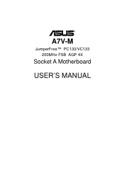
® A7V-M JumperFree™ PC133/VC133 200MHz FSB AGP 4X Socket A Motherboard USER'S MANUAL
® A7V-M JumperFree™ PC133/VC133 200MHz FSB AGP 4X Socket A Motherboard USER'S MANUAL
Motherboard DIY Troubleshooting Guide
Page 4
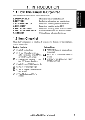
... Program 47 4.2.1 BIOS Menu Bar 48 4.2.2 Legend Bar 48 4.3 Main Menu 50 4.3.1 Primary & Secondary Master/Slave 51 4.3.2 Keyboard Features 54 4 ASUS A7V-M User's Manual CONTENTS 1. FEATURES 8 2.1 The ASUS A7V-M 8 2.1.1 Specifications 8 2.1.2 Special Features 10 2.1.3 Performance Features 10 2.1.4 Intelligence 11 2.2 Motherboard Components 12 2.2.1 Component Locations 13 3. INTRODUCTION 7 1.1 How This Manual Is Organized 7 1.2 Item Checklist 7 2. HARDWARE SETUP 14...
... Program 47 4.2.1 BIOS Menu Bar 48 4.2.2 Legend Bar 48 4.3 Main Menu 50 4.3.1 Primary & Secondary Master/Slave 51 4.3.2 Keyboard Features 54 4 ASUS A7V-M User's Manual CONTENTS 1. FEATURES 8 2.1 The ASUS A7V-M 8 2.1.1 Specifications 8 2.1.2 Special Features 10 2.1.3 Performance Features 10 2.1.4 Intelligence 11 2.2 Motherboard Components 12 2.2.1 Component Locations 13 3. INTRODUCTION 7 1.1 How This Manual Is Organized 7 1.2 Item Checklist 7 2. HARDWARE SETUP 14...
Motherboard DIY Troubleshooting Guide
Page 5
...75 4.7 Exit Menu 77 5. SOFTWARE REFERENCE 93 6.1 ASUS PC Probe 93 6.2 CyberLink PowerPlayer SE 98 6.3 CyberLink PowerDVD 98 6.4 CyberLink VideoLive Mail 100 7. SOFTWARE SETUP 79 5.1 Install Operating System 79 5.2 Start Windows 79 5.3 A7V-M Series Motherboard Support CD 80 5.4 VIA 4 in 1 drivers ...81 5.5 Audio Driver 82 5.6 Realtek RTL8139C PCI Fast Ethernet NIC Driver 83 5.7 ASUS PC Probe Vx.xx 84 5.8 ASUS Update Vx.xx 85 5.9 YAMAHA Soft Synthesizer...
...75 4.7 Exit Menu 77 5. SOFTWARE REFERENCE 93 6.1 ASUS PC Probe 93 6.2 CyberLink PowerPlayer SE 98 6.3 CyberLink PowerDVD 98 6.4 CyberLink VideoLive Mail 100 7. SOFTWARE SETUP 79 5.1 Install Operating System 79 5.2 Start Windows 79 5.3 A7V-M Series Motherboard Support CD 80 5.4 VIA 4 in 1 drivers ...81 5.5 Audio Driver 82 5.6 Realtek RTL8139C PCI Fast Ethernet NIC Driver 83 5.7 ASUS PC Probe Vx.xx 84 5.8 ASUS Update Vx.xx 85 5.9 YAMAHA Soft Synthesizer...
Motherboard DIY Troubleshooting Guide
Page 7
..." and two 3.5" floppy disk drives Optional Items ASUS CIDB chassis intrusion detection module ASUS IrDA-compliant infrared module ASUS PCI-L101 Wake-On-LAN 10/ 100 Ethernet Card (1) ASUS 2-port USB Connector Set (1) Bag of spare jumper caps (1) ASUS Support CD with drivers and utilities (1) This Motherboard User's Manual ASUS A7V-M User's Manual 7 APPENDIX Manual information and checklist...
..." and two 3.5" floppy disk drives Optional Items ASUS CIDB chassis intrusion detection module ASUS IrDA-compliant infrared module ASUS PCI-L101 Wake-On-LAN 10/ 100 Ethernet Card (1) ASUS 2-port USB Connector Set (1) Bag of spare jumper caps (1) ASUS Support CD with drivers and utilities (1) This Motherboard User's Manual ASUS A7V-M User's Manual 7 APPENDIX Manual information and checklist...

Motherboard DIY Troubleshooting Guide
Page 8
...8226; North Bridge System Chipset: Features the VIAVT8363 (VIAApollo KT133) system controller with AGP 2.0 specifications for 5 PCI masters. Appendix). 8 ASUS A7V-M User's Manual VC SDRAM is a new DRAM core architecture that support four ATA66/33 devices on two channels. 2. FEATURES Specifications 2. complies...32, 64, 128, 256, or 512MB) or NEC's VC133-compliant Virtual Channel (VC) SDRAM up to 1GB. FEATURES 2.1 The ASUS A7V-M The ASUS A7V-M motherboard is enabled. and PCI 2.2. USB controller with root hub and four function ports. • PC133 SDRAM / VC133 VCM Support: ...
...8226; North Bridge System Chipset: Features the VIAVT8363 (VIAApollo KT133) system controller with AGP 2.0 specifications for 5 PCI masters. Appendix). 8 ASUS A7V-M User's Manual VC SDRAM is a new DRAM core architecture that support four ATA66/33 devices on two channels. 2. FEATURES Specifications 2. complies...32, 64, 128, 256, or 512MB) or NEC's VC133-compliant Virtual Channel (VC) SDRAM up to 1GB. FEATURES 2.1 The ASUS A7V-M The ASUS A7V-M motherboard is enabled. and PCI 2.2. USB controller with root hub and four function ports. • PC133 SDRAM / VC133 VCM Support: ...
Motherboard DIY Troubleshooting Guide
Page 9
...to 4 USB ports, two on the back panel and two midboard, for Windows 98 compatibility, built-in this motherboard are color-coded. Power supply is used to physically transport commands and information between SMBus devices. • PCI ... information, such as CPU and systerm voltages, temperatures, and fan status through the onboard hardware ASUS ASIC and the bundled ASUS PC Probe. • SMBus: Features the System Management Bus interface, which is autodetected to ... protection, and HD/SCSI/MO/ZIP/CD/Floppy boot selection. ASUS A7V-M User's Manual 9 FEATURES Specifications 2. 2.
...to 4 USB ports, two on the back panel and two midboard, for Windows 98 compatibility, built-in this motherboard are color-coded. Power supply is used to physically transport commands and information between SMBus devices. • PCI ... information, such as CPU and systerm voltages, temperatures, and fan status through the onboard hardware ASUS ASIC and the bundled ASUS PC Probe. • SMBus: Features the System Management Bus interface, which is autodetected to ... protection, and HD/SCSI/MO/ZIP/CD/Floppy boot selection. ASUS A7V-M User's Manual 9 FEATURES Specifications 2. 2.

Motherboard DIY Troubleshooting Guide
Page 10
...busses to the memory and processor. • High-Speed Data Transfer Interface: IDE transfers using PC100-compliant SDRAMs). 10 ASUS A7V-M User's Manual This motherboard with existing DMA devices and systems so there is no need to upgrade current EIDE/ IDE drives and host systems. ...and support for operating systems that supports autodetection of hard disk drives, PS/2 mouse, and Plug and Play devices to 33MB/s. This motherboard also supports standard SDRAM, which is compatible to 66.6MB/s. FEATURES Performance 2. FEATURES 2.1.2 Special Features • ACPI Ready: Advanced ...
...busses to the memory and processor. • High-Speed Data Transfer Interface: IDE transfers using PC100-compliant SDRAMs). 10 ASUS A7V-M User's Manual This motherboard with existing DMA devices and systems so there is no need to upgrade current EIDE/ IDE drives and host systems. ...and support for operating systems that supports autodetection of hard disk drives, PS/2 mouse, and Plug and Play devices to 33MB/s. This motherboard also supports standard SDRAM, which is compatible to 66.6MB/s. FEATURES Performance 2. FEATURES 2.1.2 Special Features • ACPI Ready: Advanced ...

Motherboard DIY Troubleshooting Guide
Page 11
... and system damage. • Voltage Monitoring and Alert: System voltage levels are monitored to ensure stable voltage to critical motherboard components. ASUS A7V-M User's Manual 11 This function reduces both energy consumption and system noise, and is an important feature in implementing silent...prevent possible application crashes. Suggestions will give the user information on managing their computers from anywhere in memory on remotely through the ASUS ASIC. FEATURES 2.1.4 Intelligence • Auto Fan Off: The system fans will warn the user before the system resources are...
... and system damage. • Voltage Monitoring and Alert: System voltage levels are monitored to ensure stable voltage to critical motherboard components. ASUS A7V-M User's Manual 11 This function reduces both energy consumption and system noise, and is an important feature in implementing silent...prevent possible application crashes. Suggestions will give the user information on managing their computers from anywhere in memory on remotely through the ASUS ASIC. FEATURES 2.1.4 Intelligence • Auto Fan Off: The system fans will warn the user before the system resources are...

Motherboard DIY Troubleshooting Guide
Page 12
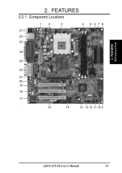
... See opposite page for Socket A AMD Athlon/Duron Processors 3 (NOTE: CPU thermal sensor is integrated on the motherboard, located near the center of the CPU heat source, just below the CPU socket) Feature Setting DIP Switches 7 Chipsets VIA VT8363 (VIA.......... 21 1 LAN (RJ45) Connector (optional Top) 26 Wake-On-LAN Connector 16 Wake-On-Ring Connector 12 Hardware Monitoring System Voltage Monitoring (integrated in ASUS ASIC) ....... 10 3 Fan Power and Speed Monitoring Connectors Power ATX Power Supply Connector 1 Others Onboard LED 5 SMBus Connector 11 Buzzer (optional 15 Form ...
... See opposite page for Socket A AMD Athlon/Duron Processors 3 (NOTE: CPU thermal sensor is integrated on the motherboard, located near the center of the CPU heat source, just below the CPU socket) Feature Setting DIP Switches 7 Chipsets VIA VT8363 (VIA.......... 21 1 LAN (RJ45) Connector (optional Top) 26 Wake-On-LAN Connector 16 Wake-On-Ring Connector 12 Hardware Monitoring System Voltage Monitoring (integrated in ASUS ASIC) ....... 10 3 Fan Power and Speed Monitoring Connectors Power ATX Power Supply Connector 1 Others Onboard LED 5 SMBus Connector 11 Buzzer (optional 15 Form ...
Motherboard DIY Troubleshooting Guide
Page 13
2. FEATURES Motherboard Parts 2. ASUS A7V-M User's Manual 13 FEATURES 2.2.1 Component Locations 12 3 4 27 26 25 5 678 24 23 22 21 20 19 18 17 16 15 14 13 12 11 10 9 -
2. FEATURES Motherboard Parts 2. ASUS A7V-M User's Manual 13 FEATURES 2.2.1 Component Locations 12 3 4 27 26 25 5 678 24 23 22 21 20 19 18 17 16 15 14 13 12 11 10 9 -
Motherboard DIY Troubleshooting Guide
Page 14
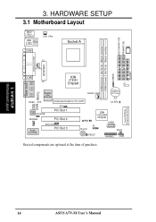
HARDWARE SETUP 3.1 Motherboard Layout PS/2 T: Mouse B: Keyboard USB Top: T: USB1 RJ-45 B: USB2 COM1 CPU_FAN Socket A SW1 SECONDARY IDE PRIMARY IDE DIMM Socket 1 (64/72-bit, 168-pin ... Lithium Cell CMOS Power CLRTC JEN Audio Codec HPHONE PCI Slot 1 MODEM PCI Slot 2 Audio Controller WOLCON PCI Slot 3 VIA VT82C686A Chipset A7V-M USB2 IR Buzzer WOR IDELED HPANEL SMB Grayed components are optional at the time of purchase. H/W SETUP Motherboard Layout 14 ASUS A7V-M User's Manual CHASS LED FLOPPY 3. Flash EEPROM (Programable BIOS) 3.
HARDWARE SETUP 3.1 Motherboard Layout PS/2 T: Mouse B: Keyboard USB Top: T: USB1 RJ-45 B: USB2 COM1 CPU_FAN Socket A SW1 SECONDARY IDE PRIMARY IDE DIMM Socket 1 (64/72-bit, 168-pin ... Lithium Cell CMOS Power CLRTC JEN Audio Codec HPHONE PCI Slot 1 MODEM PCI Slot 2 Audio Controller WOLCON PCI Slot 3 VIA VT82C686A Chipset A7V-M USB2 IR Buzzer WOR IDELED HPANEL SMB Grayed components are optional at the time of purchase. H/W SETUP Motherboard Layout 14 ASUS A7V-M User's Manual CHASS LED FLOPPY 3. Flash EEPROM (Programable BIOS) 3.

Motherboard DIY Troubleshooting Guide
Page 15
H/W SETUP Layout Contents 3. HARDWARE SETUP 3.2 Layout Contents Motherboard Settings 1) JEN p. 18 JumperFree Mode (JumperFree/Jumper Mode) 2) SW1 1-4 p. 20 CPU External Frequency Setting Expansion Slots/Sockets 1) System Memory p.21 System Memory Support 2) DIMM1/2 p.22 ...) p.40 Reset Switch Lead (2 pins) 25) PWR.SW (PANEL) p.40 ATX / Soft-Off Switch Lead (2 pins) 26) SMI (PANEL) p.40 System Management Interrupt Lead (2 pins) ASUS A7V-M User's Manual 15 3.
H/W SETUP Layout Contents 3. HARDWARE SETUP 3.2 Layout Contents Motherboard Settings 1) JEN p. 18 JumperFree Mode (JumperFree/Jumper Mode) 2) SW1 1-4 p. 20 CPU External Frequency Setting Expansion Slots/Sockets 1) System Memory p.21 System Memory Support 2) DIMM1/2 p.22 ...) p.40 Reset Switch Lead (2 pins) 25) PWR.SW (PANEL) p.40 ATX / Soft-Off Switch Lead (2 pins) 26) SMI (PANEL) p.40 System Management Interrupt Lead (2 pins) ASUS A7V-M User's Manual 15 3.

Motherboard DIY Troubleshooting Guide
Page 17
... the inside. 2. Ensure that the system is switched off mode and not powered OFF. LED A7V-M A7V-M Onboard LED ON Standby Power OFF Powered Off ASUS A7V-M User's Manual 17 If you must complete the following steps: 1. Computer motherboards and expansion cards contain very delicate Integrated Circuit (IC) chips. The onboard LED when lit acts...
... the inside. 2. Ensure that the system is switched off mode and not powered OFF. LED A7V-M A7V-M Onboard LED ON Standby Power OFF Powered Off ASUS A7V-M User's Manual 17 If you must complete the following steps: 1. Computer motherboards and expansion cards contain very delicate Integrated Circuit (IC) chips. The onboard LED when lit acts...
Motherboard DIY Troubleshooting Guide
Page 18
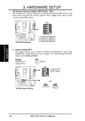
... adjusted through the BIOS setup (see 4.4 Advanced Menu). Frequency Selection 2. H/W SETUP Motherboard Settings 3. The white block represents the switch's position. Frequency Selection 3. OFF: 3) O1 2 3 4 N A7V-M A7V-M Jumper Setting JEN 12 23 Jumper Mode JumperFree™ (Default) 18 ASUS A7V-M User's Manual HARDWARE SETUP Motherboard Features Settings (DIP Switches - Frequency Selection 4. The example below shows all the...
... adjusted through the BIOS setup (see 4.4 Advanced Menu). Frequency Selection 2. H/W SETUP Motherboard Settings 3. The white block represents the switch's position. Frequency Selection 3. OFF: 3) O1 2 3 4 N A7V-M A7V-M Jumper Setting JEN 12 23 Jumper Mode JumperFree™ (Default) 18 ASUS A7V-M User's Manual HARDWARE SETUP Motherboard Features Settings (DIP Switches - Frequency Selection 4. The example below shows all the...
Motherboard DIY Troubleshooting Guide
Page 19
3. HARDWARE SETUP (This page was intentionally left blank.) 3. H/W SETUP Motherboard Settings ASUS A7V-M User's Manual 19
3. HARDWARE SETUP (This page was intentionally left blank.) 3. H/W SETUP Motherboard Settings ASUS A7V-M User's Manual 19
Motherboard DIY Troubleshooting Guide
Page 20
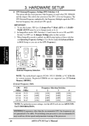
... CPU 100.00MHz PCI 33.33MHz 103.00MHz 34.33MHz ON 1234 ON 1234 A7V-M A7V-M CPU External Frequency Selection CPU 105.00MHz PCI 35.00MHz 110.00MHz 36.67MHz NOTE: The motherboard supports PC100 / PC133 DIMMs or VC SDRAMs for system memory. In JumperFree mode, SW1 Switches 1,2... DIMMs are not guaranteed to the CPU, SDRAM, and the chipset. Frequencies other than the recommended CPU bus frequencies are not supported [see ASUS CONTACT INFORMATION). It may result in 3. The CPU External Frequency multiplied by the Frequency Multiple equals the CPU's Internal frequency (the advertised CPU...
... CPU 100.00MHz PCI 33.33MHz 103.00MHz 34.33MHz ON 1234 ON 1234 A7V-M A7V-M CPU External Frequency Selection CPU 105.00MHz PCI 35.00MHz 110.00MHz 36.67MHz NOTE: The motherboard supports PC100 / PC133 DIMMs or VC SDRAMs for system memory. In JumperFree mode, SW1 Switches 1,2... DIMMs are not guaranteed to the CPU, SDRAM, and the chipset. Frequencies other than the recommended CPU bus frequencies are not supported [see ASUS CONTACT INFORMATION). It may result in 3. The CPU External Frequency multiplied by the Frequency Multiple equals the CPU's Internal frequency (the advertised CPU...

Motherboard DIY Troubleshooting Guide
Page 21
...DIMMs). tion. • DO NOT attempt to mix PC133 SDRAMs with memory chips) of the DIMM takes up one row on the motherboard. WARNING! Two sockets are not supported on bootup screen. • Single-sided DIMMs come in any combination as follows: DIMM Location ...for 3.3Volt (power level) unbuffered Synchronous Dynamic Random Access Memory (SDRAM) of choice for best performance vs. ASUS A7V-M User's Manual 21 compliant DIMMs. • ASUS motherboards support SPD (Serial Presence Detect) DIMMs. This is recommended through SDRAM Configuration under "Chipset Features Setup". Be ...
...DIMMs). tion. • DO NOT attempt to mix PC133 SDRAMs with memory chips) of the DIMM takes up one row on the motherboard. WARNING! Two sockets are not supported on bootup screen. • Single-sided DIMMs come in any combination as follows: DIMM Location ...for 3.3Volt (power level) unbuffered Synchronous Dynamic Random Access Memory (SDRAM) of choice for best performance vs. ASUS A7V-M User's Manual 21 compliant DIMMs. • ASUS motherboards support SPD (Serial Presence Detect) DIMMs. This is recommended through SDRAM Configuration under "Chipset Features Setup". Be ...
Motherboard DIY Troubleshooting Guide
Page 22
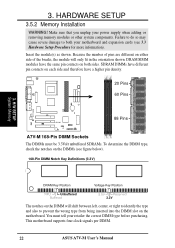
...notches on the DIMMs (see 3.3 Hardware Setup Procedure for more information). HARDWARE SETUP 3.5.2 Memory Installation WARNING! Make sure that you unplug your motherboard and expansion cards (see figure below). 168-Pin DIMM Notch Key Definitions (3.3V) 3. You must be 3.3Volt unbuffered SDRAMs. To determine ...the DIMM type, check the notches on the DIMM will only fit in the orientation shown. This motherboard supports four clock signals per DIMM. 22 ASUS A7V-M User's Manual 3. Because the number of the breaks, the module will shift between left, center, or right ...
...notches on the DIMMs (see 3.3 Hardware Setup Procedure for more information). HARDWARE SETUP 3.5.2 Memory Installation WARNING! Make sure that you unplug your motherboard and expansion cards (see figure below). 168-Pin DIMM Notch Key Definitions (3.3V) 3. You must be 3.3Volt unbuffered SDRAMs. To determine ...the DIMM type, check the notches on the DIMM will only fit in the orientation shown. This motherboard supports four clock signals per DIMM. 22 ASUS A7V-M User's Manual 3. Because the number of the breaks, the module will shift between left, center, or right ...
Motherboard DIY Troubleshooting Guide
Page 23
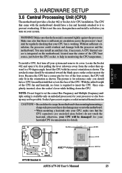
...LEVER 3. HARDWARE SETUP 3.6 Central Processing Unit (CPU) The motherboard provides a Socket 462 or Socket A for your system. otherwise, your heatsink/CPU documentation for reference only; H/W SETUP CPU LOCK AMD™ Athlon A7V-M A7V-M Socket A ASUS A7V-M User's Manual NOTCH 23 If this is not the case...processors require a socket mounted thermal resistor. Without sufficient circulation, the processor could overheat and damage both the processor and the motherboard. Locate the Socket 462 and open it to help in the orientation as shown. Make sure that came with the ...
...LEVER 3. HARDWARE SETUP 3.6 Central Processing Unit (CPU) The motherboard provides a Socket 462 or Socket A for your system. otherwise, your heatsink/CPU documentation for reference only; H/W SETUP CPU LOCK AMD™ Athlon A7V-M A7V-M Socket A ASUS A7V-M User's Manual NOTCH 23 If this is not the case...processors require a socket mounted thermal resistor. Without sufficient circulation, the processor could overheat and damage both the processor and the motherboard. Locate the Socket 462 and open it to help in the orientation as shown. Make sure that came with the ...

Motherboard DIY Troubleshooting Guide
Page 25
... on the slot with the screw you intend to use . 3. Keep the bracket for your expansion card. 3. H/W SETUP Expansion Cards ASUS A7V-M User's Manual 25 Secure the card on the slot you removed above. 5. Remove your motherboard and expansion cards. 3.7.1 Expansion Card Installation Procedure 1. Install the necessary software drivers for possible future use . 3.
... on the slot with the screw you intend to use . 3. Keep the bracket for your expansion card. 3. H/W SETUP Expansion Cards ASUS A7V-M User's Manual 25 Secure the card on the slot you removed above. 5. Remove your motherboard and expansion cards. 3.7.1 Expansion Card Installation Procedure 1. Install the necessary software drivers for possible future use . 3.


