Motherboard DIY Troubleshooting Guide
Page 2
.... For previous or updated manuals, BIOS, drivers, or product release information, contact ASUS at http://www.asus.com.tw or through any means, except documentation kept by ASUS; All Rights Reserved. Product Name: ASUS A7M266 Manual Revision: 1.04 E776 Release Date: May 2001 2 ASUS A7M266 User's Manual Copyright © 2001 ASUSTeK COMPUTER INC. SPECIFICATIONS AND INFORMATION CONTAINED...
.... For previous or updated manuals, BIOS, drivers, or product release information, contact ASUS at http://www.asus.com.tw or through any means, except documentation kept by ASUS; All Rights Reserved. Product Name: ASUS A7M266 Manual Revision: 1.04 E776 Release Date: May 2001 2 ASUS A7M266 User's Manual Copyright © 2001 ASUSTeK COMPUTER INC. SPECIFICATIONS AND INFORMATION CONTAINED...

Motherboard DIY Troubleshooting Guide
Page 3
...) Notebook (Tel): +886-2-2890-7122 (English) Desktop/Server (Tel):+886-2-2890-7123 (English) Fax: +886-2-2893-7775 Email: tsd@asus.com.tw WWW: www.asus.com.tw FTP: ftp.asus.com.tw/pub/ASUS ASUS COMPUTER INTERNATIONAL (America) Marketing Address: 6737 Mowry Avenue, Mowry Business Center, Building 2 Newark, CA 94560, USA Fax: +1-510-608-4555... Fax: +49-2102-9599-11 Support (Email): www.asuscom.de/de/support (for online support) WWW: www.asuscom.de FTP: ftp.asuscom.de/pub/ASUSCOM ASUS A7M266 User's Manual 3
...) Notebook (Tel): +886-2-2890-7122 (English) Desktop/Server (Tel):+886-2-2890-7123 (English) Fax: +886-2-2893-7775 Email: tsd@asus.com.tw WWW: www.asus.com.tw FTP: ftp.asus.com.tw/pub/ASUS ASUS COMPUTER INTERNATIONAL (America) Marketing Address: 6737 Mowry Avenue, Mowry Business Center, Building 2 Newark, CA 94560, USA Fax: +1-510-608-4555... Fax: +49-2102-9599-11 Support (Email): www.asuscom.de/de/support (for online support) WWW: www.asuscom.de FTP: ftp.asuscom.de/pub/ASUSCOM ASUS A7M266 User's Manual 3
Motherboard DIY Troubleshooting Guide
Page 4
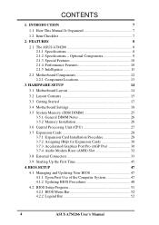
... 30 3.7.3 Accelerated Graphics Port Pro (AGP Pro 30 3.7.4 Audio Modem Riser (AMR) Slot 32 3.8 External Connectors 33 3.9 Starting Up the First Time 45 4. FEATURES 8 2.1 The ASUS A7M266 8 2.1.1 Specifications 8 2.1.2 Specifications - INTRODUCTION 7 1.1 How This Manual Is Organized 7 1.2 Item Checklist 7 2. BIOS SETUP 47 4.1 Managing and Updating Your BIOS 47 4.1.1 Upon First Use of the Computer...
... 30 3.7.3 Accelerated Graphics Port Pro (AGP Pro 30 3.7.4 Audio Modem Riser (AMR) Slot 32 3.8 External Connectors 33 3.9 Starting Up the First Time 45 4. FEATURES 8 2.1 The ASUS A7M266 8 2.1.1 Specifications 8 2.1.2 Specifications - INTRODUCTION 7 1.1 How This Manual Is Organized 7 1.2 Item Checklist 7 2. BIOS SETUP 47 4.1 Managing and Updating Your BIOS 47 4.1.1 Upon First Use of the Computer...

Motherboard DIY Troubleshooting Guide
Page 5
... 92 6.3 YAMAHA XGPlayer 93 7. APPENDIX 97 7.1 Modem Riser 97 7.2 Glossary 99 ASUS A7M266 User's Manual 5 SOFTWARE SETUP 83 5.1 Install Operating System 83 5.2 Start Windows 83 5.3 A7 Series Motherboard Support CD 83 5.4 Uninstalling Programs 85 6. CONTENTS 4.3 Main Menu 54 4.3.1 ...
... 92 6.3 YAMAHA XGPlayer 93 7. APPENDIX 97 7.1 Modem Riser 97 7.2 Glossary 99 ASUS A7M266 User's Manual 5 SOFTWARE SETUP 83 5.1 Install Operating System 83 5.2 Start Windows 83 5.3 A7 Series Motherboard Support CD 83 5.4 Uninstalling Programs 85 6. CONTENTS 4.3 Main Menu 54 4.3.1 ...

Motherboard DIY Troubleshooting Guide
Page 6
... of Federal Regulations #47, part 15.193, 1993. Cet appareil numérique de la classe B est conforme à la norme NMB-003 du Canada. 6 ASUS A7M266 User's Manual However, there is subject to provide reasonable protection against harmful interference in violation of Part 15 of the Federal Register, National Archives and...
... of Federal Regulations #47, part 15.193, 1993. Cet appareil numérique de la classe B est conforme à la norme NMB-003 du Canada. 6 ASUS A7M266 User's Manual However, there is subject to provide reasonable protection against harmful interference in violation of Part 15 of the Federal Register, National Archives and...

Motherboard DIY Troubleshooting Guide
Page 7
... motherboard. 4. INTRODUCTION 1.1 How This Manual Is Organized This manual is complete. Package Contents (1) ASUS Motherboard (1) 40-pin 80-conductor ribbon cable for internal UltraDMA/ 100 / UltraDMA/66 (also compatible with drivers and utilities (1) This Motherboard User's Manual ASUS A7M266 User's Manual 7 HARDWARE SETUP Instructions on setting up the BIOS 5. FEATURES Production information and...
... motherboard. 4. INTRODUCTION 1.1 How This Manual Is Organized This manual is complete. Package Contents (1) ASUS Motherboard (1) 40-pin 80-conductor ribbon cable for internal UltraDMA/ 100 / UltraDMA/66 (also compatible with drivers and utilities (1) This Motherboard User's Manual ASUS A7M266 User's Manual 7 HARDWARE SETUP Instructions on setting up the BIOS 5. FEATURES Production information and...

Motherboard DIY Troubleshooting Guide
Page 8
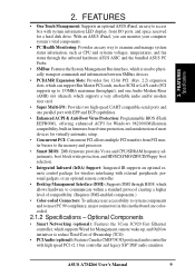
... ports, two on two channels. Appendix). • Wake-On-Ring Connector: Supports Wake-On-Ring activity through an optional ASUS PCI-L101 10/100 Fast Ethernet PCI card (see 7. FEATURES 2.1 The ASUS A7M266 The ASUS A7M266 motherboard is optimized to deliver enhanced AMD Athlon™ processor system performance. • "Super South" South Bridge System PCIset... and PCI 2.2. USB controller with root hub and four function ports. • PC2100 / PC1600 DDR SDRAM Support: Equipped with support for more peripheral connectivity options. 8 ASUS A7M266 User's Manual AC97 audio;
... ports, two on two channels. Appendix). • Wake-On-Ring Connector: Supports Wake-On-Ring activity through an optional ASUS PCI-L101 10/100 Fast Ethernet PCI card (see 7. FEATURES 2.1 The ASUS A7M266 The ASUS A7M266 motherboard is optimized to deliver enhanced AMD Athlon™ processor system performance. • "Super South" South Bridge System PCIset... and PCI 2.2. USB controller with root hub and four function ports. • PC2100 / PC1600 DDR SDRAM Support: Equipped with support for more peripheral connectivity options. 8 ASUS A7M266 User's Manual AC97 audio;
Motherboard DIY Troubleshooting Guide
Page 9
..., an easy to access box with high speed PCI v2.1 bus controller and legacy SB® DSP audio emulator. ASUS A7M266 User's Manual 9 Optional Components • Smart Networking (optional): Features the 3Com 3C920 Fast Ethernet controller, which supports Wired for ...external peripherals, personal gadgets, or an optional remote controller. • Desktop Management Interface (DMI): Supports DMI through the onboard hardware ASUS ASIC and the bundled ASUS PC Probe. • SMBus: Features the System Management Bus interface, which is used to physically transport commands and information between ...
..., an easy to access box with high speed PCI v2.1 bus controller and legacy SB® DSP audio emulator. ASUS A7M266 User's Manual 9 Optional Components • Smart Networking (optional): Features the 3Com 3C920 Fast Ethernet controller, which supports Wired for ...external peripherals, personal gadgets, or an optional remote controller. • Desktop Management Interface (DMI): Supports DMI through the onboard hardware ASUS ASIC and the bundled ASUS PC Probe. • SMBus: Features the System Management Bus interface, which is used to physically transport commands and information between ...
Motherboard DIY Troubleshooting Guide
Page 10
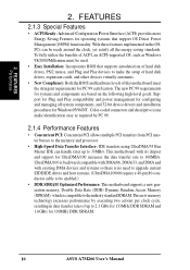
... other devices virtually automatic. • New Compliancy: Both the BIOS and hardware levels of this motherboard meet the stringent requirements for 100MHz DDR SDRAM. 10 ASUS A7M266 User's Manual UltraDMA/100 is compatible to 33MB/s. This new memory technology increases performance by PC 99. 2.1.4 Performance Features • Concurrent PCI: Concurrent PCI allows...
... other devices virtually automatic. • New Compliancy: Both the BIOS and hardware levels of this motherboard meet the stringent requirements for 100MHz DDR SDRAM. 10 ASUS A7M266 User's Manual UltraDMA/100 is compatible to 33MB/s. This new memory technology increases performance by PC 99. 2.1.4 Performance Features • Concurrent PCI: Concurrent PCI allows...

Motherboard DIY Troubleshooting Guide
Page 11
.... 2. With this benefit on the BIOS or OS setting (see PWR Button < 4 Secs in memory on remotely through the ASUS ASIC. ASUS A7M266 User's Manual 11 FEATURES 2.1.5 Intelligence • Dual Function Power Button: Pushing the power button for future processors, so monitoring is monitored... by the ASUS ASIC to prevent system overheat and system damage. • Voltage Monitoring and Alert: System voltage levels are ...
.... 2. With this benefit on the BIOS or OS setting (see PWR Button < 4 Secs in memory on remotely through the ASUS ASIC. ASUS A7M266 User's Manual 11 FEATURES 2.1.5 Intelligence • Dual Function Power Button: Pushing the power button for future processors, so monitoring is monitored... by the ASUS ASIC to prevent system overheat and system damage. • Voltage Monitoring and Alert: System voltage levels are ...

Motherboard DIY Troubleshooting Guide
Page 12
... 3Com 3C920 Fast Ethernet Controller 14 1 LAN (RJ45) Connector Top) 23 Wake-On-LAN Connector 12 Wake-On-Ring Connector 10 Hardware Monitoring ASUS ASIC 9 3 Fan Power and Speed Monitoring Connectors Power ATX Power Supply Connector 18 Special Feature Onboard LED 11 Form Factor ATX 12 ASUS A7M266 User's Manual FEATURES Motherboard Parts 2.
... 3Com 3C920 Fast Ethernet Controller 14 1 LAN (RJ45) Connector Top) 23 Wake-On-LAN Connector 12 Wake-On-Ring Connector 10 Hardware Monitoring ASUS ASIC 9 3 Fan Power and Speed Monitoring Connectors Power ATX Power Supply Connector 18 Special Feature Onboard LED 11 Form Factor ATX 12 ASUS A7M266 User's Manual FEATURES Motherboard Parts 2.

Motherboard DIY Troubleshooting Guide
Page 13
FEATURES 2.2.1 Component Locations 12 3 24 23 22 21 20 19 18 17 16 15 14 45 13 12 11 10 9 8 76 ASUS A7M266 User's Manual 13 FEATURES Motherboard Parts 2. 2.
FEATURES 2.2.1 Component Locations 12 3 24 23 22 21 20 19 18 17 16 15 14 45 13 12 11 10 9 8 76 ASUS A7M266 User's Manual 13 FEATURES Motherboard Parts 2. 2.

Motherboard DIY Troubleshooting Guide
Page 14
... Lithium Cell CMOS Power VIA VT82C686B ® PCIset CLRTC JTPWR JEN CHA_FAN USBPORT ASUS USBPWR2 CHASSIS ASIC with Hardware IR Monitor AFPANEL IDELED SMB PANEL Grayed components are available only on certain models at the time of purchase. 14 ASUS A7M266 User's Manual H/W SETUP Motherboard Layout 3. PRIMARY IDE SECONDARY IDE 2Mbit Flash EEPROM...
... Lithium Cell CMOS Power VIA VT82C686B ® PCIset CLRTC JTPWR JEN CHA_FAN USBPORT ASUS USBPWR2 CHASSIS ASIC with Hardware IR Monitor AFPANEL IDELED SMB PANEL Grayed components are available only on certain models at the time of purchase. 14 ASUS A7M266 User's Manual H/W SETUP Motherboard Layout 3. PRIMARY IDE SECONDARY IDE 2Mbit Flash EEPROM...

Motherboard DIY Troubleshooting Guide
Page 15
HARDWARE SETUP 3.2 Layout Contents 3. 3. ASUS A7M266 User's Manual 15 H/W SETUP Layout Contents Motherboard Settings 1) JEN p. 19 JumperFree Mode (JumperFree / Jumper Mode) 2) VIO VIO1 p. 20 Clock Generator Voltage Setting (3.30V / 3.56V / 3.45V) +2.... p. 39 Chassis, Power Supply, CPU, Chipset Fan Connectors (3 pins) 16) USBPORT p. 40 USB Header (10-1 pins) 17) SMB p. 40 SMBus Connector (5-1 pins) 18) AFPANEL p. 41 ASUS iPanel Connector (24-1 pins) continued...
HARDWARE SETUP 3.2 Layout Contents 3. 3. ASUS A7M266 User's Manual 15 H/W SETUP Layout Contents Motherboard Settings 1) JEN p. 19 JumperFree Mode (JumperFree / Jumper Mode) 2) VIO VIO1 p. 20 Clock Generator Voltage Setting (3.30V / 3.56V / 3.45V) +2.... p. 39 Chassis, Power Supply, CPU, Chipset Fan Connectors (3 pins) 16) USBPORT p. 40 USB Header (10-1 pins) 17) SMB p. 40 SMBus Connector (5-1 pins) 18) AFPANEL p. 41 ASUS iPanel Connector (24-1 pins) continued...

Motherboard DIY Troubleshooting Guide
Page 16
HARDWARE SETUP 19) JTPWR 20) ATXPWR 21) IDELED 22) PWR.LED (PANEL) 23) SPEAKER (PANEL) 24) MSG.LED (PANEL) 25) SMI (PANEL) 26) PWR.SW (PANEL) 27) RESET (PANEL) p. 41 Power Supply Thermal Sensor Connector (2 pins) p. 42 ATX Power Supply Connector (20 pins) p. 42 IDE Activity LED (2 pins) p. 43 System Power LED Lead (3 pins) p. 43 System Warning Speaker Connector (4 pins) p. 43 System Message LED (2 pins) p. 43 System Management Interrupt Lead (2 pins) p. 43 ATX / Soft-Off Switch Lead (2 pins) p. 43 Reset Switch Lead (2 pins) 3. H/W SETUP Layout Contents 16 ASUS A7M266 User's Manual 3.
HARDWARE SETUP 19) JTPWR 20) ATXPWR 21) IDELED 22) PWR.LED (PANEL) 23) SPEAKER (PANEL) 24) MSG.LED (PANEL) 25) SMI (PANEL) 26) PWR.SW (PANEL) 27) RESET (PANEL) p. 41 Power Supply Thermal Sensor Connector (2 pins) p. 42 ATX Power Supply Connector (20 pins) p. 42 IDE Activity LED (2 pins) p. 43 System Power LED Lead (3 pins) p. 43 System Warning Speaker Connector (4 pins) p. 43 System Message LED (2 pins) p. 43 System Management Interrupt Lead (2 pins) p. 43 ATX / Soft-Off Switch Lead (2 pins) p. 43 Reset Switch Lead (2 pins) 3. H/W SETUP Layout Contents 16 ASUS A7M266 User's Manual 3.

Motherboard DIY Troubleshooting Guide
Page 17
Install Memory Modules 3. Connect Ribbon Cables, Panel Wires, and Power Supply 6. 3. Install the Central Processing Unit (CPU) 4. Setup the BIOS Software 3. Install Expansion Cards 5. H/W SETUP Getting Started ASUS A7M266 User's Manual 17 HARDWARE SETUP 3.3 Getting Started Before using your computer, you must complete the following steps: 1. Check Motherboard Settings 2.
Install Memory Modules 3. Connect Ribbon Cables, Panel Wires, and Power Supply 6. 3. Install the Central Processing Unit (CPU) 4. Setup the BIOS Software 3. Install Expansion Cards 5. H/W SETUP Getting Started ASUS A7M266 User's Manual 17 HARDWARE SETUP 3.3 Getting Started Before using your computer, you must complete the following steps: 1. Check Motherboard Settings 2.

Motherboard DIY Troubleshooting Guide
Page 18
... unplug your motherboard, peripherals, and/or components. To protect them against damage from the system. 5. 3. H/W SETUP Motherboard Settings 01 01 A7M266 ® A7M266 Onboard LED ON Standby Power OFF Powered Off 18 ASUS A7M266 User's Manual HARDWARE SETUP 3.4 Motherboard Settings This section explains in suspend or soft-off before handling computer components. The onboard...
... unplug your motherboard, peripherals, and/or components. To protect them against damage from the system. 5. 3. H/W SETUP Motherboard Settings 01 01 A7M266 ® A7M266 Onboard LED ON Standby Power OFF Powered Off 18 ASUS A7M266 User's Manual HARDWARE SETUP 3.4 Motherboard Settings This section explains in suspend or soft-off before handling computer components. The onboard...

Motherboard DIY Troubleshooting Guide
Page 19
... 1) JumperFree™ Mode (JEN) This jumper allows you to be set to [3-4]. ASUS A7M266 User's Manual 19 Setting JumperFree Jumper Mode JEN [2-3] (default) [1-2] 34 VID4 VID3 VID2 VID1 A7M266 ® A7M266 JumperFree Mode Setting 12 23 Jumper Mode Jumper Free (Default) JEN NOTE: In JumperFree&#...8482; mode, all the switches in the OFF position. 01 01 01 01 A7M266 ® A7M266 DIP Switch DSCKF ON 1234 OFF ON 1. Frequency Selection 4. 3. H/W SETUP Motherboard Settings 3. The JumperFree™ mode allows processor...
... 1) JumperFree™ Mode (JEN) This jumper allows you to be set to [3-4]. ASUS A7M266 User's Manual 19 Setting JumperFree Jumper Mode JEN [2-3] (default) [1-2] 34 VID4 VID3 VID2 VID1 A7M266 ® A7M266 JumperFree Mode Setting 12 23 Jumper Mode Jumper Free (Default) JEN NOTE: In JumperFree&#...8482; mode, all the switches in the OFF position. 01 01 01 01 A7M266 ® A7M266 DIP Switch DSCKF ON 1234 OFF ON 1. Frequency Selection 4. 3. H/W SETUP Motherboard Settings 3. The JumperFree™ mode allows processor...

Motherboard DIY Troubleshooting Guide
Page 20
...'s life. Setting Disable Enable LAN_EN [1-2] [2-3] (default) 3. The default voltage should be enabled or disabled using this jumper. H/W SETUP Motherboard Settings A7M266 ® A7M266 Lan Setting LAN_EN 12 23 Disable Enable (default) 20 ASUS A7M266 User's Manual It is strongly recommended that you to select the voltage supplied to the clock generator and VIO1 (for...
...'s life. Setting Disable Enable LAN_EN [1-2] [2-3] (default) 3. The default voltage should be enabled or disabled using this jumper. H/W SETUP Motherboard Settings A7M266 ® A7M266 Lan Setting LAN_EN 12 23 Disable Enable (default) 20 ASUS A7M266 User's Manual It is strongly recommended that you to select the voltage supplied to the clock generator and VIO1 (for...

Motherboard DIY Troubleshooting Guide
Page 21
...is set to allow wake up from the S1 sleep state (CPU stopped; Setting +5V +5VSB USBPWR1, USBPWR2 [2-3] (default) [1-2] A7M266 ® A7M266 USB Device Wake Up USBPWR1 USBPWR2 12 23 +5VSB +5V (default) 5) Onboard PCI Audio Setting (AUDIO_EN) (optional) The onboard PCI...(USBPWR1, USBPWR2) Set these jumpers are set this jumper. Setting Disable Enable AUDIO_EN [1-2] [2-3] (default) A7M266 ® AUDIO_EN 12 23 Disable Enable (Default) A7M266 Onboard Audio Setting ASUS A7M266 User's Manual 21 3. The default is required when these jumpers to +5V to allow wake up from...
...is set to allow wake up from the S1 sleep state (CPU stopped; Setting +5V +5VSB USBPWR1, USBPWR2 [2-3] (default) [1-2] A7M266 ® A7M266 USB Device Wake Up USBPWR1 USBPWR2 12 23 +5VSB +5V (default) 5) Onboard PCI Audio Setting (AUDIO_EN) (optional) The onboard PCI...(USBPWR1, USBPWR2) Set these jumpers are set this jumper. Setting Disable Enable AUDIO_EN [1-2] [2-3] (default) A7M266 ® AUDIO_EN 12 23 Disable Enable (Default) A7M266 Onboard Audio Setting ASUS A7M266 User's Manual 21 3. The default is required when these jumpers to +5V to allow wake up from...


