

User Guide
Page 2
..., model number and version, as required under the Lesser General Public License Version ("LGPL") and/or other additional data, you want to have it shipped to, by sending a request to the owners' benefit, without the express written permission of alteration is authorized in this manual, including the products and software described in it from http://support.asus.com/download...
..., model number and version, as required under the Lesser General Public License Version ("LGPL") and/or other additional data, you want to have it shipped to, by sending a request to the owners' benefit, without the express written permission of alteration is authorized in this manual, including the products and software described in it from http://support.asus.com/download...

User Guide
Page 4
... manuals that your retailer. Contact a qualified service technician or your power supply is organized This guide contains the following parts: • Chapter 1: Product introduction This chapter describes the features of the motherboard and the new technology it by yourself. If you add a device. • Before connecting or removing signal cables from the motherboard, ensure that the power cables for the devices are unplugged before the signal cables...
... manuals that your retailer. Contact a qualified service technician or your power supply is organized This guide contains the following parts: • Chapter 1: Product introduction This chapter describes the features of the motherboard and the new technology it by yourself. If you add a device. • Before connecting or removing signal cables from the motherboard, ensure that the power cables for the devices are unplugged before the signal cables...
User Guide
Page 6
... items. Motherboard Cables Accessories Application DVD Documentation ASUS A58M-E motherboard 2 x Serial ATA 3.0 Gb/s cables 1 x I/O Shield Support DVD User Guide If any of 4GB capacity or more, Windows® 32-bit operating system may only recognize less than 3GB. AMD® A58 FCH (Bolton D2) 2 x DDR3 DIMM, max. 32GB, DDR3 2400 (O.C.) / 2133* / 1866 / 1600 / 1333 MHz, non-ECC un-buffered memory Dual-channel memory architecture Supports AMD Memory Profile (AMP) memory * Hyper DIMM support is damaged...
... items. Motherboard Cables Accessories Application DVD Documentation ASUS A58M-E motherboard 2 x Serial ATA 3.0 Gb/s cables 1 x I/O Shield Support DVD User Guide If any of 4GB capacity or more, Windows® 32-bit operating system may only recognize less than 3GB. AMD® A58 FCH (Bolton D2) 2 x DDR3 DIMM, max. 32GB, DDR3 2400 (O.C.) / 2133* / 1866 / 1600 / 1333 MHz, non-ECC un-buffered memory Dual-channel memory architecture Supports AMD Memory Profile (AMP) memory * Hyper DIMM support is damaged...

User Guide
Page 7
... - A58M-E specifications summary Storage / RAID LAN Audio USB ASUS unique features AMD® A58 FCH: - 6 x Serial ATA 3.0Gb/s connectors (dark brown) support RAID 0, RAID 1, RAID 10, and JBOD configurations Realtek® 8111GR Gigabit LAN controller Realtek® ALC887-VD 7.1-channel High Definition Audio CODEC • Use a chassis with HD audio module in the front panel to ensure the best quality, reliability, and durability ASUS Digi+ VRM - ASUS motherboards safeguard your PC with excellent durability ASUS Stainless Steel Back I /O to support a 7.1-channel audio...
... - A58M-E specifications summary Storage / RAID LAN Audio USB ASUS unique features AMD® A58 FCH: - 6 x Serial ATA 3.0Gb/s connectors (dark brown) support RAID 0, RAID 1, RAID 10, and JBOD configurations Realtek® 8111GR Gigabit LAN controller Realtek® ALC887-VD 7.1-channel High Definition Audio CODEC • Use a chassis with HD audio module in the front panel to ensure the best quality, reliability, and durability ASUS Digi+ VRM - ASUS motherboards safeguard your PC with excellent durability ASUS Stainless Steel Back I /O to support a 7.1-channel audio...

User Guide
Page 8
...channel audio I/O ports (3-jack) 2 x USB 2.0 connectors support additional 4 USB 2.0 ports 6 x SATA 3.0Gb/s connectors 1 x COM connector 1 x TPM header 1 x System panel connector 1 x Internal Speaker connector 1 x 4-pin CPU fan connector 1 x S/PDIF output connector 1 x 4-pin Chassis fan connector 1 x High Definition Front panel audio connector 1 x 24-pin EATX power connector 1 x 4-pin ATX 12V power connector 64 Mb Flash ROM, UEFI AMI BIOS, PnP, DMI 2.0, WfM 2.0, SM BIOS v2.6, ACPI 2.0a Drivers ASUS Update ASUS utilities Anti-Virus software (OEM version) Windows® 8.1, 32bit/64-bit Windows...
...channel audio I/O ports (3-jack) 2 x USB 2.0 connectors support additional 4 USB 2.0 ports 6 x SATA 3.0Gb/s connectors 1 x COM connector 1 x TPM header 1 x System panel connector 1 x Internal Speaker connector 1 x 4-pin CPU fan connector 1 x S/PDIF output connector 1 x 4-pin Chassis fan connector 1 x High Definition Front panel audio connector 1 x 24-pin EATX power connector 1 x 4-pin ATX 12V power connector 64 Mb Flash ROM, UEFI AMI BIOS, PnP, DMI 2.0, WfM 2.0, SM BIOS v2.6, ACPI 2.0a Drivers ASUS Update ASUS utilities Anti-Virus software (OEM version) Windows® 8.1, 32bit/64-bit Windows...
User Guide
Page 9
... to the motherboard, peripherals, or components. 1.2 Motherboard overview Before you install the motherboard, study the configuration of your chassis to ensure that the ATX power supply is switched off or the power cord is detached from the wall socket before touching any component. • Before handling components, use a grounded wrist strap or touch a safely grounded object or a metal object, such as the power supply case, to avoid...
... to the motherboard, peripherals, or components. 1.2 Motherboard overview Before you install the motherboard, study the configuration of your chassis to ensure that the ATX power supply is switched off or the power cord is detached from the wall socket before touching any component. • Before handling components, use a grounded wrist strap or touch a safely grounded object or a metal object, such as the power supply case, to avoid...

User Guide
Page 11
... motherboard comes with an FM2+ socket designed for the FM2+ socket. USB 2.0 connectors (10-1 pin USB34, USB56) 9. A58M-E A58M-E CPU socket FM2+ Ensure that you use an APU designed for AMD® A-series / Athlon™ Series graphics. TPM connector (20-1 pin TPM) 11. DO NOT force the APU into the socket to prevent bending the pins and damaging the APU! Connectors/Jumpers/Slots/LED 1. DDR3 DIMM slots 5. ASUS A58M-E 1-3 System panel connector (10-1 pin F_PANEL) 8. Digital audio connector (4-1 pin SPDIF_OUT) 12. CPU and chassis fan connectors (4-pin...
... motherboard comes with an FM2+ socket designed for the FM2+ socket. USB 2.0 connectors (10-1 pin USB34, USB56) 9. A58M-E A58M-E CPU socket FM2+ Ensure that you use an APU designed for AMD® A-series / Athlon™ Series graphics. TPM connector (20-1 pin TPM) 11. DO NOT force the APU into the socket to prevent bending the pins and damaging the APU! Connectors/Jumpers/Slots/LED 1. DDR3 DIMM slots 5. ASUS A58M-E 1-3 System panel connector (10-1 pin F_PANEL) 8. Digital audio connector (4-1 pin SPDIF_OUT) 12. CPU and chassis fan connectors (4-pin...
User Guide
Page 15
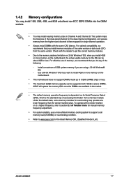
... Tweaker menu for manual memory frequency adjustment. • For system stability, use of memory, we recommend that you want to www.asus.com for single-channel operation. • Always install DIMMs with 16GB or above DIMMs. ASUS will update the memory QVL once the DIMMs are using a 32-bit Windows® OS. - Use a 64-bit Windows® OS if you do any of the same version or date code (D/C) from a memory...
... Tweaker menu for manual memory frequency adjustment. • For system stability, use of memory, we recommend that you want to www.asus.com for single-channel operation. • Always install DIMMs with 16GB or above DIMMs. ASUS will update the memory QVL once the DIMMs are using a 32-bit Windows® OS. - Use a 64-bit Windows® OS if you do any of the same version or date code (D/C) from a memory...

User Guide
Page 17
... card. ASUS A58M-E 1-9 Turn on BIOS setup. 2. When using PCI cards on the slot. 5. Align the card connector with PCI specifications. Install the software drivers for information on the system and change the necessary BIOS settings, if any. Otherwise, conflicts will arise between the two PCI groups, making the system unstable and the card inoperable. 1.5.3 PCI slot The PCI slot supports cards such as a LAN card, SCSI card, USB card, and other cards that comply with the slot and press firmly until the card is already installed...
... card. ASUS A58M-E 1-9 Turn on BIOS setup. 2. When using PCI cards on the slot. 5. Align the card connector with PCI specifications. Install the software drivers for information on the system and change the necessary BIOS settings, if any. Otherwise, conflicts will arise between the two PCI groups, making the system unstable and the card inoperable. 1.5.3 PCI slot The PCI slot supports cards such as a LAN card, SCSI card, USB card, and other cards that comply with the slot and press firmly until the card is already installed...

User Guide
Page 18
... Chip USB OHCI 1/2/3/4 - - HD audio shared - - - - - - - shared - - - - - 1.6 Jumpers Clear RTC RAM (3-pin CLRTC) This jumper allows you to clear the Real Time Clock (RTC) RAM in CMOS, which include system setup information such as system passwords. A58M-E CLRTC 12 23 Normal (Default) A58M-E Clear RTC RAM Clear RTC 1-10 Chapter 1: Product introduction 1.5.4 PCI Express x1 slot This motherboard supports PCI Express 2.0 x1 network cards, SCSI cards, and other cards that comply with the PCI Express specifications. 1.5.5 PCI Express x16 slot This motherboard supports...
... Chip USB OHCI 1/2/3/4 - - HD audio shared - - - - - - - shared - - - - - 1.6 Jumpers Clear RTC RAM (3-pin CLRTC) This jumper allows you to clear the Real Time Clock (RTC) RAM in CMOS, which include system setup information such as system passwords. A58M-E CLRTC 12 23 Normal (Default) A58M-E Clear RTC RAM Clear RTC 1-10 Chapter 1: Product introduction 1.5.4 PCI Express x1 slot This motherboard supports PCI Express 2.0 x1 network cards, SCSI cards, and other cards that comply with the PCI Express specifications. 1.5.5 PCI Express x16 slot This motherboard supports...

User Guide
Page 19
... to a Local Area Network (LAN) through a network hub. This 15-pin port is for a PS/2 mouse. 2. Keep the cap on CLRTC jumper default position. enter data. Video Graphics Adapter (VGA) port. ASUS A58M-E 1-11 LAN (RJ-45) port. Turn OFF the computer and unplug the power cord. 2. Shut down the key during the boot process and enter BIOS setup to default values. 1.7 Connectors 1.7.1 Rear panel connectors 1 2 3 45 10 9 8 7 6 1. This port allows Gigabit connection to overclocking, use the CPU Parameter Recall (C.P.R.) feature. Hold...
... to a Local Area Network (LAN) through a network hub. This 15-pin port is for a PS/2 mouse. 2. Keep the cap on CLRTC jumper default position. enter data. Video Graphics Adapter (VGA) port. ASUS A58M-E 1-11 LAN (RJ-45) port. Turn OFF the computer and unplug the power cord. 2. Shut down the key during the boot process and enter BIOS setup to default values. 1.7 Connectors 1.7.1 Rear panel connectors 1 2 3 45 10 9 8 7 6 1. This port allows Gigabit connection to overclocking, use the CPU Parameter Recall (C.P.R.) feature. Hold...

User Guide
Page 21
... FAN IN CHA FAN PWR GND A58M-E A58M-E Fan connectors DO NOT forget to connect the fan cables to the fan connectors on the fan connectors. • The CPU_FAN connector supports a CPU fan of the connector. DO NOT place jumper caps on the motherboard, ensuring that the black wire of each cable matches the ground pin of maximum 2A (24 W) fan power. • The CPU_FAN and CHA_FAN connectors support the ASUS Fan Xpert feature. 2. A TPM system also helps enhance network...
... FAN IN CHA FAN PWR GND A58M-E A58M-E Fan connectors DO NOT forget to connect the fan cables to the fan connectors on the fan connectors. • The CPU_FAN connector supports a CPU fan of the connector. DO NOT place jumper caps on the motherboard, ensuring that the black wire of each cable matches the ground pin of maximum 2A (24 W) fan power. • The CPU_FAN and CHA_FAN connectors support the ASUS Fan Xpert feature. 2. A TPM system also helps enhance network...
User Guide
Page 23
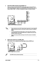
...GND A58M-E SATA 3.0Gb/s connectors • These connectors are using Windows® XP SP3 or later version. • When using hot-plug and NCQ, set the type of the SATA connectors in the BIOS to AHCI mode by default. If you installed Serial ATA hard disk drives, you intend to create a Serial ATA RAID set using Serial ATA hard disk drives. Digital audio connector (4-1 pin SPDIF_OUT) This connector is for Serial ATA hard disk drives and optical disc drives. The Serial ATA RAID feature is purchased separately. ASUS A58M-E 1-15 Serial ATA 3.0 Gb/s connectors (7-pin SATA3G...
...GND A58M-E SATA 3.0Gb/s connectors • These connectors are using Windows® XP SP3 or later version. • When using hot-plug and NCQ, set the type of the SATA connectors in the BIOS to AHCI mode by default. If you installed Serial ATA hard disk drives, you intend to create a Serial ATA RAID set using Serial ATA hard disk drives. Digital audio connector (4-1 pin SPDIF_OUT) This connector is for Serial ATA hard disk drives and optical disc drives. The Serial ATA RAID feature is purchased separately. ASUS A58M-E 1-15 Serial ATA 3.0 Gb/s connectors (7-pin SATA3G...

User Guide
Page 25
... chassis-mounted system warning speaker. The speaker allows you want to connect a high definition front panel audio module to this connector. SPEAKER A58M-E PIN 1 A58M-E Speaker Out Connector +5V GND GND Speaker Out ASUS A58M-E 1-17 7. Connect one end of the motherboard high-definition audio capability. • If you to this connector, set the Front Panel Type item in the BIOS to [HD]. • The front panel audio I /O module cable to hear system beeps and warnings. Front panel audio connector (10-1 pin AAFP) This connector...
... chassis-mounted system warning speaker. The speaker allows you want to connect a high definition front panel audio module to this connector. SPEAKER A58M-E PIN 1 A58M-E Speaker Out Connector +5V GND GND Speaker Out ASUS A58M-E 1-17 7. Connect one end of the motherboard high-definition audio capability. • If you to this connector, set the Front Panel Type item in the BIOS to [HD]. • The front panel audio I /O module cable to hear system beeps and warnings. Front panel audio connector (10-1 pin AAFP) This connector...

User Guide
Page 27
... updates. ASUS A58M-E 1-19 Refer to your computer, the DVD automatically displays the Specials screen which contains the unique features of the Support DVD to install If Autorun is enabled in your hardware. • Motherboard settings and hardware options vary. The following screen is for better compatibility and system stability. 1.8.2 Support DVD information The Support DVD that comes with the motherboard package contains the drivers, software applications, and utilities that you install Windows® XP Service...
... updates. ASUS A58M-E 1-19 Refer to your computer, the DVD automatically displays the Specials screen which contains the unique features of the Support DVD to install If Autorun is enabled in your hardware. • Motherboard settings and hardware options vary. The following screen is for better compatibility and system stability. 1.8.2 Support DVD information The Support DVD that comes with the motherboard package contains the drivers, software applications, and utilities that you install Windows® XP Service...
User Guide
Page 29
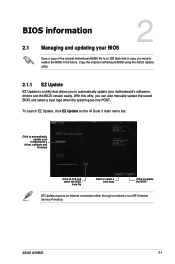
... 3 main menu bar. Click to find and select the BIOS from file Click to select a boot logo Click to automatically update your motherboard's softwares, drivers and the BIOS version easily. Copy the original motherboard BIOS using the ASUS Update utility. 2.1.1 EZ Update EZ Update is a utility that allows you to automatically update your motherboard's driver, software and firmware Model Name: A58M-E Version:0203 Release Date: 01/28/2014 File: A58M-E-ASUS-0205.CAP Model Name: A58M-E Version:0205 Release Date: 02/12/2014 C:\Users\test\Downloads\A58M-E-ASUS...
... 3 main menu bar. Click to find and select the BIOS from file Click to select a boot logo Click to automatically update your motherboard's softwares, drivers and the BIOS version easily. Copy the original motherboard BIOS using the ASUS Update utility. 2.1.1 EZ Update EZ Update is a utility that allows you to automatically update your motherboard's driver, software and firmware Model Name: A58M-E Version:0203 Release Date: 01/28/2014 File: A58M-E-ASUS-0205.CAP Model Name: A58M-E Version:0205 Release Date: 02/12/2014 C:\Users\test\Downloads\A58M-E-ASUS...

User Guide
Page 30
... boot failure! 2.1.3 ASUS CrashFree BIOS 3 utility The ASUS CrashFree BIOS 3 is an auto recovery tool that contains the updated BIOS file. • Before using the motherboard support DVD or a USB flash drive that allows you to the USB port. 2. Press to switch to the Folder Info field. 6. Press to switch to the Drive field. 4. Enter the Advanced Mode of the BIOS setup program. Press the Up/Down arrow keys to find the USB flash disk that contains the latest BIOS file to restore the BIOS file...
... boot failure! 2.1.3 ASUS CrashFree BIOS 3 utility The ASUS CrashFree BIOS 3 is an auto recovery tool that contains the updated BIOS file. • Before using the motherboard support DVD or a USB flash drive that allows you to the USB port. 2. Press to switch to the Folder Info field. 6. Press to switch to the Drive field. 4. Enter the Advanced Mode of the BIOS setup program. Press the Up/Down arrow keys to find the USB flash disk that contains the latest BIOS file to restore the BIOS file...
User Guide
Page 31
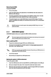
... BIOS setting. The utility automatically checks the devices for reference only and may not be exactly the same as the boot device. ASUS A58M-E 2-3 Doing so can cause system boot failure! 2.1.4 ASUS BIOS Updater ASUS BIOS Updater allows you to enter BIOS Setup to launch the select boot device screen. 3. Recovering the BIOS To recover the BIOS: 1. DO NOT shut down or reset the system while updating the BIOS! Before updating BIOS • Prepare the motherboard support DVD and a USB flash drive. • Download the latest BIOS file...
... BIOS setting. The utility automatically checks the devices for reference only and may not be exactly the same as the boot device. ASUS A58M-E 2-3 Doing so can cause system boot failure! 2.1.4 ASUS BIOS Updater ASUS BIOS Updater allows you to enter BIOS Setup to launch the select boot device screen. 3. Recovering the BIOS To recover the BIOS: 1. DO NOT shut down or reset the system while updating the BIOS! Before updating BIOS • Prepare the motherboard support DVD and a USB flash drive. • Download the latest BIOS file...

User Guide
Page 32
... BIOS Updater screen, press to Drives panel then select D:. 2-4 Chapter 2: Getting started Press ENTER to boot from Files panel to switch from the DVD/CD. Please select boot device: E1: ASUS DVD-E818A6T (4069MB) USB DISK 2.0 (3824MB) UEFI: (FAT) USB DISK 2.0 (3824MB) Enter Setup and to move selection ENTER to select boot device ESC to Drive D (USB flash drive). ISOLINUX 3.20 2006-08-26 Copyright (C) 1994-2005 H. On the FreeDOS prompt, type d: then press to switch the disk from Drive C (optical drive) to boot using defaults...
... BIOS Updater screen, press to Drives panel then select D:. 2-4 Chapter 2: Getting started Press ENTER to boot from Files panel to switch from the DVD/CD. Please select boot device: E1: ASUS DVD-E818A6T (4069MB) USB DISK 2.0 (3824MB) UEFI: (FAT) USB DISK 2.0 (3824MB) Enter Setup and to move selection ENTER to select boot device ESC to Drive D (USB flash drive). ISOLINUX 3.20 2006-08-26 Copyright (C) 1994-2005 H. On the FreeDOS prompt, type d: then press to switch the disk from Drive C (optical drive) to boot using defaults...

User Guide
Page 34
... the Load Optimized Defaults item under two modes: EZ Mode and Advanced Mode. Entering BIOS Setup after POST To enter BIOS Setup after POST: • Press ++ simultaneously. • Press the reset button on the system chassis. • Press the power button to turn the system off then back on how to the default value. Using the power button, reset button, or the ++ keys to force reset from a running operating system can cause damage to update the BIOS or configure its...
... the Load Optimized Defaults item under two modes: EZ Mode and Advanced Mode. Entering BIOS Setup after POST To enter BIOS Setup after POST: • Press ++ simultaneously. • Press the reset button on the system chassis. • Press the power button to turn the system off then back on how to the default value. Using the power button, reset button, or the ++ keys to force reset from a running operating system can cause damage to update the BIOS or configure its...


