
A55M-A User's Manual
Page 1
Motherboard A55M-A Series • A55M-A • A55M-A/USB3
Motherboard A55M-A Series • A55M-A • A55M-A/USB3

A55M-A User's Manual
Page 3
Contents Safety information...vi About this guide...vii A55M-A Series specifications summary ix Package contents...xi Product introduction 1.1 Special features 1-1 1.1.1 Product highlights 1-1 1.1.2 ASUS DIGI+ VRM 1-1 1.1.3 ASUS Exclusive Features 1-2 1.2 Before you proceed 1-4 1.3 Motherboard overview 1-5 1.3.1 Placement direction 1-5 1.3.2 Screw holes 1-5 1.3.3 Motherboard layout 1-6 1.3.4 Layout contents 1-7 1.4 Accelerated Processing Unit (APU 1-7 1.4.1 APU installation 1-8 1.4.2 APU heatsink and fan assembly installation 1-9 1.5 System memory 1-11...
Contents Safety information...vi About this guide...vii A55M-A Series specifications summary ix Package contents...xi Product introduction 1.1 Special features 1-1 1.1.1 Product highlights 1-1 1.1.2 ASUS DIGI+ VRM 1-1 1.1.3 ASUS Exclusive Features 1-2 1.2 Before you proceed 1-4 1.3 Motherboard overview 1-5 1.3.1 Placement direction 1-5 1.3.2 Screw holes 1-5 1.3.3 Motherboard layout 1-6 1.3.4 Layout contents 1-7 1.4 Accelerated Processing Unit (APU 1-7 1.4.1 APU installation 1-8 1.4.2 APU heatsink and fan assembly installation 1-9 1.5 System memory 1-11...
A55M-A User's Manual
Page 6
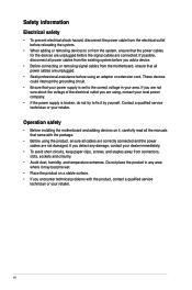
...you are not sure about the voltage of the electrical outlet you add a device. • Before connecting or removing signal cables from the motherboard, ensure that your power supply is broken, do not try to fix it , carefully read all the manuals that the power cables for ... from the existing system before you are unplugged. • Seek professional assistance before the signal cables are connected. Operation safety • Before installing the motherboard and adding devices on a stable surface. • If you detect any area where it may become wet. • Place the product on it...
...you are not sure about the voltage of the electrical outlet you add a device. • Before connecting or removing signal cables from the motherboard, ensure that your power supply is broken, do not try to fix it , carefully read all the manuals that the power cables for ... from the existing system before you are unplugged. • Seek professional assistance before the signal cables are connected. Operation safety • Before installing the motherboard and adding devices on a stable surface. • If you detect any area where it may become wet. • Place the product on it...
A55M-A User's Manual
Page 7
vii Detailed descriptions of the motherboard and the new technology it supports. • Chapter 2: BIOS information This chapter tells how to change system settings through the BIOS Setup menus. Where to find more information Refer to the ASUS contact information. 2. Refer to the following parts: • Chapter 1: Product introduction This chapter describes the...
vii Detailed descriptions of the motherboard and the new technology it supports. • Chapter 2: BIOS information This chapter tells how to change system settings through the BIOS Setup menus. Where to find more information Refer to the ASUS contact information. 2. Refer to the following parts: • Chapter 1: Product introduction This chapter describes the...
A55M-A User's Manual
Page 11
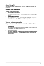
.... • If any of the above items is damaged or missing, contact your motherboard package for reference only. Package contents Check your retailer. • The illustrated items ...A55M-A/USB3 PCIEX16 RTL 8111F PCIEX1_1 BATTERY Super I/O PCI1 SB_PWR ALC 887 SPDIF_OUT AAFP USBPWF USB56 USB34 AMD® A55 SATA6G_5 SATA6G_6 SATA6G_3 SATA6G_4 SATA6G_1 SATA6G_2 32Mb BIOS CLRTC SPEAKER F_PANEL EATXPWR ASUS A55M-A Series motherboard User Guide 2 x Serial ATA 3.0 Gb/s cables 1 x I/O Shield User Guide Support DVD • A55M-A Series motherboards include A55M-A and A55M...
.... • If any of the above items is damaged or missing, contact your motherboard package for reference only. Package contents Check your retailer. • The illustrated items ...A55M-A/USB3 PCIEX16 RTL 8111F PCIEX1_1 BATTERY Super I/O PCI1 SB_PWR ALC 887 SPDIF_OUT AAFP USBPWF USB56 USB34 AMD® A55 SATA6G_5 SATA6G_6 SATA6G_3 SATA6G_4 SATA6G_1 SATA6G_2 32Mb BIOS CLRTC SPEAKER F_PANEL EATXPWR ASUS A55M-A Series motherboard User Guide 2 x Serial ATA 3.0 Gb/s cables 1 x I/O Shield User Guide Support DVD • A55M-A Series motherboards include A55M-A and A55M...
A55M-A User's Manual
Page 13
... 11 graphics in FM2 socket compatible CPUs ASUS A55M-A Series 1-1 Product introduction 1 1.1 Special features 1.1.1 Product highlights AMD® A-series accelerated processors with AMD® Radeon™ HD 7000 series graphics This motherboard supports AMD® A-series accelerated processors with...and Internet applications. 100% All High-quality Conductive Polymer Capacitors This motherboard uses all high-quality conductive polymer capacitors for durability, improved lifespan, and enhanced thermal capacity. 1.1.2 ASUS DIGI+ VRM DIGI+POWER CONTROL: Digital Power Design for the APU...
... 11 graphics in FM2 socket compatible CPUs ASUS A55M-A Series 1-1 Product introduction 1 1.1 Special features 1.1.1 Product highlights AMD® A-series accelerated processors with AMD® Radeon™ HD 7000 series graphics This motherboard supports AMD® A-series accelerated processors with...and Internet applications. 100% All High-quality Conductive Polymer Capacitors This motherboard uses all high-quality conductive polymer capacitors for durability, improved lifespan, and enhanced thermal capacity. 1.1.2 ASUS DIGI+ VRM DIGI+POWER CONTROL: Digital Power Design for the APU...
A55M-A User's Manual
Page 14
... world's first real-time system power-saving chip, automatically detects the current system load and intelligently moderates power usage. ASUS Anti-Surge Protection This special design protects expensive devices and the motherboard from damage caused by configuring profiles through the inuitive user interface. It allows you to configure the overclocking settings, adjust...
... world's first real-time system power-saving chip, automatically detects the current system load and intelligently moderates power usage. ASUS Anti-Surge Protection This special design protects expensive devices and the motherboard from damage caused by configuring profiles through the inuitive user interface. It allows you to configure the overclocking settings, adjust...

A55M-A User's Manual
Page 16
... ON OFF Standby Power Powered Off A55M-A/USB3 Onboard LED 1-4 Chapter 1: Product introduction 1.2 Before you proceed Take note of the onboard LED. The illustration below shows the location of the following precautions before you install motherboard components or change any motherboard settings. • Unplug the power cord ... any component, place it on a grounded antistatic pad or in the bag that came with a standby power LED that lights up to the motherboard, peripherals, or components. This is a reminder that the system is ON, in sleep mode, or in any component, switch off mode....
... ON OFF Standby Power Powered Off A55M-A/USB3 Onboard LED 1-4 Chapter 1: Product introduction 1.2 Before you proceed Take note of the onboard LED. The illustration below shows the location of the following precautions before you install motherboard components or change any motherboard settings. • Unplug the power cord ... any component, place it on a grounded antistatic pad or in the bag that came with a standby power LED that lights up to the motherboard, peripherals, or components. This is a reminder that the system is ON, in sleep mode, or in any component, switch off mode....
A55M-A User's Manual
Page 17
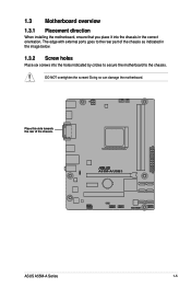
The edge with external ports goes to the chassis. Place this side towards the rear of the chassis as indicated in the correct orientation. Doing so can damage the motherboard. DO NOT overtighten the screws! A55M-A/USB3 ASUS A55M-A Series 1-5 1.3 Motherboard overview 1.3.1 Placement direction When installing the motherboard, ensure that you place it into the chassis in the image below. 1.3.2 Screw holes Place six screws into the holes indicated by circles to secure the motherboard to the rear part of the chassis.
The edge with external ports goes to the chassis. Place this side towards the rear of the chassis as indicated in the correct orientation. Doing so can damage the motherboard. DO NOT overtighten the screws! A55M-A/USB3 ASUS A55M-A Series 1-5 1.3 Motherboard overview 1.3.1 Placement direction When installing the motherboard, ensure that you place it into the chassis in the image below. 1.3.2 Screw holes Place six screws into the holes indicated by circles to secure the motherboard to the rear part of the chassis.
A55M-A User's Manual
Page 18
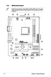
...64bit, 240-pin module) DDR3 DIMM_B1 (64bit, 240-pin module) SOCKET FM2 DVI_VGA USB1112 23.6cm(9.3in) LAN1_USB12 ASM 1042 EATXPWR KB_USBWB AUDIO 2 A55M-A/USB3 PCIEX16 RTL 8111F Super I/O PCIEX1_1 BATTERY PCI1 SATA6G_5 SATA6G_6 AMD® A55 SATA6G_3 SATA6G_4 6 SB_PWR ALC 887 SPDIF_OUT AAFP SATA6G_1 SATA6G_2 USBPWF 32Mb BIOS... USB56 USB34 CLRTC SPEAKER 7 F_PANEL 14 13 12 11 10 98 1-6 Chapter 1: Product introduction The package contents vary between models. 1.3.3 Motherboard layout A55M-A Series motherboards include A55M-A and A55M-A/USB3 models.
...64bit, 240-pin module) DDR3 DIMM_B1 (64bit, 240-pin module) SOCKET FM2 DVI_VGA USB1112 23.6cm(9.3in) LAN1_USB12 ASM 1042 EATXPWR KB_USBWB AUDIO 2 A55M-A/USB3 PCIEX16 RTL 8111F Super I/O PCIEX1_1 BATTERY PCI1 SATA6G_5 SATA6G_6 AMD® A55 SATA6G_3 SATA6G_4 6 SB_PWR ALC 887 SPDIF_OUT AAFP SATA6G_1 SATA6G_2 USBPWF 32Mb BIOS... USB56 USB34 CLRTC SPEAKER 7 F_PANEL 14 13 12 11 10 98 1-6 Chapter 1: Product introduction The package contents vary between models. 1.3.3 Motherboard layout A55M-A Series motherboards include A55M-A and A55M-A/USB3 models.

A55M-A User's Manual
Page 19
...SB_PWR) Page 1-21 1-24 1-7 1-23 1-11 1-25 1-26 1-26 1-20 1-28 1-21 1-27 1-27 1-4 1.4 Accelerated Processing Unit (APU) This motherboard comes with AMD® Radeon™ HD 7000 series graphics. Clear RTC RAM (3-pin CLRTC) 10. DO NOT force the APU into the socket to... correct orientation. Keyboard power (3-pin KB_USBPWB) 2. CPU fan connector (4-pin CPU_FAN) and Chassis fan connector (3-pin CHA_FAN) 5. A55M-A/USB3 A55M-A/USB3 CPU socket FM2 ASUS A55M-A Series 1-7 Ensure that you use a APU designed for AMD® A-series accelerated processors with an FM2 socket designed for the...
...SB_PWR) Page 1-21 1-24 1-7 1-23 1-11 1-25 1-26 1-26 1-20 1-28 1-21 1-27 1-27 1-4 1.4 Accelerated Processing Unit (APU) This motherboard comes with AMD® Radeon™ HD 7000 series graphics. Clear RTC RAM (3-pin CLRTC) 10. DO NOT force the APU into the socket to... correct orientation. Keyboard power (3-pin KB_USBPWB) 2. CPU fan connector (4-pin CPU_FAN) and Chassis fan connector (3-pin CHA_FAN) 5. A55M-A/USB3 A55M-A/USB3 CPU socket FM2 ASUS A55M-A Series 1-7 Ensure that you use a APU designed for AMD® A-series accelerated processors with an FM2 socket designed for the...

A55M-A User's Manual
Page 23
The figure illustrates the location of the DDR3 DIMM sockets: DIMM_A1 DIMM_B1 A55M-A/USB3 Channel Channel A Channel B A55M-A/USB3 240-pin DDR3 DIMM sockets Sockets DIMM_A1 DIMM_B1 ASUS A55M-A Series 1-11 DDR3 modules are developed for better performance with two Double Data Rate 3 (DDR3) Dual Inline Memory Modules (DIMM) sockets. 1.5 System memory 1.5.1 Overview This motherboard comes with less power consumption. A DDR3 module has the same physical dimensions as a DDR2 DIMM but is notched differently to prevent installation on a DDR2 DIMM socket.
The figure illustrates the location of the DDR3 DIMM sockets: DIMM_A1 DIMM_B1 A55M-A/USB3 Channel Channel A Channel B A55M-A/USB3 240-pin DDR3 DIMM sockets Sockets DIMM_A1 DIMM_B1 ASUS A55M-A Series 1-11 DDR3 modules are developed for better performance with two Double Data Rate 3 (DDR3) Dual Inline Memory Modules (DIMM) sockets. 1.5 System memory 1.5.1 Overview This motherboard comes with less power consumption. A DDR3 module has the same physical dimensions as a DDR2 DIMM but is notched differently to prevent installation on a DDR2 DIMM socket.
A55M-A User's Manual
Page 24
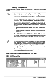
Any excess memory from the same vendor. G.SKILL F3-14900CL10Q2-64GBZLD(XMP1.3) 64GB(8GB x 8) DS - Chip NO. A55M-A Series Motherboard Qualified Vendors Lists (QVL) DDR3 1866 MHz capability Vendors Part No. CORSAIR CMZ8GX3M2A1866C9(XMP) 8GB(2 x 4GB) DS - Timing DIMM socket Voltage support (... or more memory on its Serial Presence Detect (SPD), which is dependent on the motherboard, the actual usable memory for single-channel operation. • Always install DIMMs with 16GB or above DIMMs. ASUS will update the memory QVL once the DIMMs are using a 32-bit Windows®...
Any excess memory from the same vendor. G.SKILL F3-14900CL10Q2-64GBZLD(XMP1.3) 64GB(8GB x 8) DS - Chip NO. A55M-A Series Motherboard Qualified Vendors Lists (QVL) DDR3 1866 MHz capability Vendors Part No. CORSAIR CMZ8GX3M2A1866C9(XMP) 8GB(2 x 4GB) DS - Timing DIMM socket Voltage support (... or more memory on its Serial Presence Detect (SPD), which is dependent on the motherboard, the actual usable memory for single-channel operation. • Always install DIMMs with 16GB or above DIMMs. ASUS will update the memory QVL once the DIMMs are using a 32-bit Windows®...
A55M-A User's Manual
Page 30
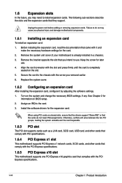
...came with the screw you may cause you intend to the card. 3. Remove the bracket opposite the slot that you physical injury and damage motherboard components. 1.6.1 Installing an expansion card To install an expansion card: 1. Replace the system cover. 1.6.2 Configuring an expansion card After installing the ...graphics card that the cards do so may need IRQ assignments. Turn on BIOS setup. 2. Remove the system unit cover (if your motherboard is completely seated on shared slots, ensure that the drivers support "Share IRQ" or that complies with the slot and press firmly ...
...came with the screw you may cause you intend to the card. 3. Remove the bracket opposite the slot that you physical injury and damage motherboard components. 1.6.1 Installing an expansion card To install an expansion card: 1. Replace the system cover. 1.6.2 Configuring an expansion card After installing the ...graphics card that the cards do so may need IRQ assignments. Turn on BIOS setup. 2. Remove the system unit cover (if your motherboard is completely seated on shared slots, ensure that the drivers support "Share IRQ" or that complies with the slot and press firmly ...
A55M-A User's Manual
Page 31
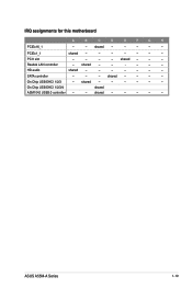
On Chip USB EHCI 1/2/3/4 shared ASM1042 USB3.0 controller - - shared - - - Realtek LAN controller - shared - - - - - - PCI1 slot - - - - HD audio shared - - - - - - - On Chip USB EHCI 1/2/3 - shared - - - - - PCIEx1_1 shared - - - - - - - ASUS A55M-A Series 1-19 shared - - - - - shared - - - - IRQ assignments for this motherboard A B C D E F G H PCIEx16_1 - - shared - - - - - - SATA controller - - -
On Chip USB EHCI 1/2/3/4 shared ASM1042 USB3.0 controller - - shared - - - Realtek LAN controller - shared - - - - - - PCI1 slot - - - - HD audio shared - - - - - - - On Chip USB EHCI 1/2/3 - shared - - - - - PCIEx1_1 shared - - - - - - - ASUS A55M-A Series 1-19 shared - - - - - shared - - - - IRQ assignments for this motherboard A B C D E F G H PCIEx16_1 - - shared - - - - - - SATA controller - - -

A55M-A User's Manual
Page 35
...CPU FAN PWR GND Rotation +12V GND ASUS A55M-A Series 1-23 These two 4-pin Universal Serial Bus (USB) ports are for USB 2.0/1.1 devices. 9. DVI-D port. These are for USB 2.0/1.1 devices. 8. DO NOT place jumper caps on the motherboard, ensuring that the black wire of ... for any DVI-D compatible device. Insufficient air flow inside the system may damage the motherboard components. USB 3.0 ports 11 and 12 (A55M-A/USB3 only). HDMI port. PS/2 Keyboard port (purple). USB 2.0 ports 11 and 12 (A55M-A only). This port is for a PS/2 keyboard. 1.8.2 Internal connectors 1. 7....
...CPU FAN PWR GND Rotation +12V GND ASUS A55M-A Series 1-23 These two 4-pin Universal Serial Bus (USB) ports are for USB 2.0/1.1 devices. 9. DVI-D port. These are for USB 2.0/1.1 devices. 8. DO NOT place jumper caps on the motherboard, ensuring that the black wire of ... for any DVI-D compatible device. Insufficient air flow inside the system may damage the motherboard components. USB 3.0 ports 11 and 12 (A55M-A/USB3 only). HDMI port. PS/2 Keyboard port (purple). USB 2.0 ports 11 and 12 (A55M-A only). This port is for a PS/2 keyboard. 1.8.2 Internal connectors 1. 7....
A55M-A User's Manual
Page 39
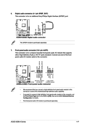
Connect one end of the motherboard high-definition audio capability. • If you connect a high-definition front panel audio module to this connector to avail of the front panel audio I/O module cable to this connector, set the Front Panel Type item in the BIOS to this connector. ASUS A55M-A Series 1-27 6. Front panel audio...
Connect one end of the motherboard high-definition audio capability. • If you connect a high-definition front panel audio module to this connector to avail of the front panel audio I/O module cable to this connector, set the Front Panel Type item in the BIOS to this connector. ASUS A55M-A Series 1-27 6. Front panel audio...

A55M-A User's Manual
Page 40
USB56 USB34 USB+5V USB_P6USB_P6+ GND NC USB+5V USB_P4USB_P4+ GND NC A55M-A/USB3 PIN 1 PIN 1 USB+5V USB_P5USB_P5+ GND USB+5V USB_P3USB_P3+ GND A55M-A/USB3 USB2.0 connectors Never connect a 1394 cable to a slot opening at the back of the system chassis. 8. The USB 2.0 module is purchased separately. 1-28 Chapter... install the module to the USB connectors. USB 2.0 connectors (10-1 pin USB56, USB34) These connectors are for USB 2.0 ports. Doing so will damage the motherboard! These USB connectors comply with USB 2.0 specification that supports up to 480Mbps connection speed.
USB56 USB34 USB+5V USB_P6USB_P6+ GND NC USB+5V USB_P4USB_P4+ GND NC A55M-A/USB3 PIN 1 PIN 1 USB+5V USB_P5USB_P5+ GND USB+5V USB_P3USB_P3+ GND A55M-A/USB3 USB2.0 connectors Never connect a 1394 cable to a slot opening at the back of the system chassis. 8. The USB 2.0 module is purchased separately. 1-28 Chapter... install the module to the USB connectors. USB 2.0 connectors (10-1 pin USB56, USB34) These connectors are for USB 2.0 ports. Doing so will damage the motherboard! These USB connectors comply with USB 2.0 specification that supports up to 480Mbps connection speed.
A55M-A User's Manual
Page 41
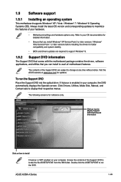
If Autorun is enabled in your OS documentation for detailed information. • Ensure that you can install to avail all motherboard features. Click Drivers, Utilities, Make Disk, Manual, and Contact tabs to install If Autorun is for updates. Double-click the ASSETUP.EXE to ... Support DVD Place the Support DVD into the optical drive. The contents of the Support DVD to change at www.asus.com for reference only. ASUS A55M-A Series 1-29 Visit the ASUS website at any time without notice. To run the DVD. Always install the latest OS version and corresponding updates to...
If Autorun is enabled in your OS documentation for detailed information. • Ensure that you can install to avail all motherboard features. Click Drivers, Utilities, Make Disk, Manual, and Contact tabs to install If Autorun is for updates. Double-click the ASSETUP.EXE to ... Support DVD Place the Support DVD into the optical drive. The contents of the Support DVD to change at www.asus.com for reference only. ASUS A55M-A Series 1-29 Visit the ASUS website at any time without notice. To run the DVD. Always install the latest OS version and corresponding updates to...
A55M-A User's Manual
Page 43
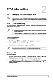
... support DVD that allows you update the BIOS using the ASUS Update utility. 2.1.1 ASUS Update utility The ASUS Update is a utility that comes with the motherboard package. Updating the BIOS To update the BIOS: 1. The ASUS Update main screen appears. Quit all Windows® applications... menu appears. 2. Follow the onscreen instructions to manage, save, and update the motherboard BIOS in Windows® environment. • ASUS Update requires an Internet connection either of the original motherboard BIOS file to a USB flash disk in the optical drive. Click Update button ...
... support DVD that allows you update the BIOS using the ASUS Update utility. 2.1.1 ASUS Update utility The ASUS Update is a utility that comes with the motherboard package. Updating the BIOS To update the BIOS: 1. The ASUS Update main screen appears. Quit all Windows® applications... menu appears. 2. Follow the onscreen instructions to manage, save, and update the motherboard BIOS in Windows® environment. • ASUS Update requires an Internet connection either of the original motherboard BIOS file to a USB flash disk in the optical drive. Click Update button ...


