A55M-A User's Manual
Page 11
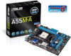
... (64bit, 240-pin module) DDR3 DIMM_B1 (64bit, 240-pin module) SOCKET FM2 DVI_VGA USB1112 LAN1_USB12 ASM 1042 AUDIO KB_USBWB A55M-A/USB3 PCIEX16 RTL 8111F PCIEX1_1 BATTERY Super I/O PCI1 SB_PWR ALC 887 SPDIF_OUT AAFP USBPWF USB56 USB34 AMD® A55 SATA6G_5 SATA6G_6... SATA6G_3 SATA6G_4 SATA6G_1 SATA6G_2 32Mb BIOS CLRTC SPEAKER F_PANEL EATXPWR ASUS A55M-A Series motherboard User Guide 2 x Serial ATA 3.0 Gb/s cables 1 x I/O Shield User Guide Support DVD • A55M-A Series motherboards include A55M-A and A55M-A/USB3 models. xi
... (64bit, 240-pin module) DDR3 DIMM_B1 (64bit, 240-pin module) SOCKET FM2 DVI_VGA USB1112 LAN1_USB12 ASM 1042 AUDIO KB_USBWB A55M-A/USB3 PCIEX16 RTL 8111F PCIEX1_1 BATTERY Super I/O PCI1 SB_PWR ALC 887 SPDIF_OUT AAFP USBPWF USB56 USB34 AMD® A55 SATA6G_5 SATA6G_6... SATA6G_3 SATA6G_4 SATA6G_1 SATA6G_2 32Mb BIOS CLRTC SPEAKER F_PANEL EATXPWR ASUS A55M-A Series motherboard User Guide 2 x Serial ATA 3.0 Gb/s cables 1 x I/O Shield User Guide Support DVD • A55M-A Series motherboards include A55M-A and A55M-A/USB3 models. xi
A55M-A User's Manual
Page 13
...processing power and advanced DirectX 11 graphics in FM2 socket compatible CPUs ASUS A55M-A Series 1-1 AMD® A55 FCH chipset AMD® A55 FCH is designed to support up to assure unmitigated performance, ASUS A55 boards with AMD® Radeon™ HD 7000 series graphics...all high-quality conductive polymer capacitors for durability, improved lifespan, and enhanced thermal capacity. 1.1.2 ASUS DIGI+ VRM DIGI+POWER CONTROL: Digital Power Design for the APU* ASUS motherboards using userdefined profiles. The result is adjusted either through carefully developed automated modes, or ...
...processing power and advanced DirectX 11 graphics in FM2 socket compatible CPUs ASUS A55M-A Series 1-1 AMD® A55 FCH chipset AMD® A55 FCH is designed to support up to assure unmitigated performance, ASUS A55 boards with AMD® Radeon™ HD 7000 series graphics...all high-quality conductive polymer capacitors for durability, improved lifespan, and enhanced thermal capacity. 1.1.2 ASUS DIGI+ VRM DIGI+POWER CONTROL: Digital Power Design for the APU* ASUS motherboards using userdefined profiles. The result is adjusted either through carefully developed automated modes, or ...
A55M-A User's Manual
Page 15
ASUS CrashFree BIOS 3 ASUS CrashFree BIOS 3 allows you to personalize your favorite photos into 256-color boot logos to restore a corrupted BIOS file from a USB storage device that contains the BIOS file. ASUS A55M-A Series 1-3 ASUS software automatically accelerates data speeds for compatible USB 3.0 peripherals without the need for any user interaction. ASUS MyLogo2™ Turn your system. USB 3.0 Boost (A55M-A/USB3 only) With USB 3.0 Boost technology, a USB device's transmission speed is significantly increased, adding to an already impressive USB 3.0 transfer speed.
ASUS CrashFree BIOS 3 ASUS CrashFree BIOS 3 allows you to personalize your favorite photos into 256-color boot logos to restore a corrupted BIOS file from a USB storage device that contains the BIOS file. ASUS A55M-A Series 1-3 ASUS software automatically accelerates data speeds for compatible USB 3.0 peripherals without the need for any user interaction. ASUS MyLogo2™ Turn your system. USB 3.0 Boost (A55M-A/USB3 only) With USB 3.0 Boost technology, a USB device's transmission speed is significantly increased, adding to an already impressive USB 3.0 transfer speed.
A55M-A User's Manual
Page 17
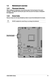
The edge with external ports goes to the rear part of the chassis. A55M-A/USB3 ASUS A55M-A Series 1-5 1.3 Motherboard overview 1.3.1 Placement direction When installing the motherboard, ensure that you place it into the chassis in the image below. 1.3.2 Screw holes Place six screws into the holes indicated by circles to secure the motherboard to the chassis. DO NOT overtighten the screws! Doing so can damage the motherboard. Place this side towards the rear of the chassis as indicated in the correct orientation.
The edge with external ports goes to the rear part of the chassis. A55M-A/USB3 ASUS A55M-A Series 1-5 1.3 Motherboard overview 1.3.1 Placement direction When installing the motherboard, ensure that you place it into the chassis in the image below. 1.3.2 Screw holes Place six screws into the holes indicated by circles to secure the motherboard to the chassis. DO NOT overtighten the screws! Doing so can damage the motherboard. Place this side towards the rear of the chassis as indicated in the correct orientation.

A55M-A User's Manual
Page 19
...) This motherboard comes with an FM2 socket designed for the FM2 socket. The APU fits in only one correct orientation. AMD FM2 socket 4. A55M-A/USB3 A55M-A/USB3 CPU socket FM2 ASUS A55M-A Series 1-7 CPU fan connector (4-pin CPU_FAN) and Chassis fan connector (3-pin CHA_FAN) 5. Ensure that you use a APU designed for AMD® A-series...
...) This motherboard comes with an FM2 socket designed for the FM2 socket. The APU fits in only one correct orientation. AMD FM2 socket 4. A55M-A/USB3 A55M-A/USB3 CPU socket FM2 ASUS A55M-A Series 1-7 CPU fan connector (4-pin CPU_FAN) and Chassis fan connector (3-pin CHA_FAN) 5. Ensure that you use a APU designed for AMD® A-series...

A55M-A User's Manual
Page 21
To install the APU heatsink and fan assembly 1 2 3 4 5 ASUS A55M-A Series 1-9 1.4.2 APU heatsink and fan assembly installation Apply the Thermal Interface Material to the APU heatsink and APU before you install the heatsink and fan if necessary.
To install the APU heatsink and fan assembly 1 2 3 4 5 ASUS A55M-A Series 1-9 1.4.2 APU heatsink and fan assembly installation Apply the Thermal Interface Material to the APU heatsink and APU before you install the heatsink and fan if necessary.

A55M-A User's Manual
Page 23
DDR3 modules are developed for better performance with two Double Data Rate 3 (DDR3) Dual Inline Memory Modules (DIMM) sockets. A DDR3 module has the same physical dimensions as a DDR2 DIMM but is notched differently to prevent installation on a DDR2 DIMM socket. The figure illustrates the location of the DDR3 DIMM sockets: DIMM_A1 DIMM_B1 A55M-A/USB3 Channel Channel A Channel B A55M-A/USB3 240-pin DDR3 DIMM sockets Sockets DIMM_A1 DIMM_B1 ASUS A55M-A Series 1-11 1.5 System memory 1.5.1 Overview This motherboard comes with less power consumption.
DDR3 modules are developed for better performance with two Double Data Rate 3 (DDR3) Dual Inline Memory Modules (DIMM) sockets. A DDR3 module has the same physical dimensions as a DDR2 DIMM but is notched differently to prevent installation on a DDR2 DIMM socket. The figure illustrates the location of the DDR3 DIMM sockets: DIMM_A1 DIMM_B1 A55M-A/USB3 Channel Channel A Channel B A55M-A/USB3 240-pin DDR3 DIMM sockets Sockets DIMM_A1 DIMM_B1 ASUS A55M-A Series 1-11 1.5 System memory 1.5.1 Overview This motherboard comes with less power consumption.
A55M-A User's Manual
Page 27
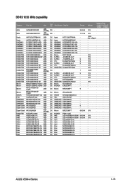
... J2108BCSE-DJ-F - KINGSTON KVR1333D3N9/4G-SP 4GB DS KINGSTON D2568JENCPGD9U - Micron MT8JTF25664AZ-1G4D1 2GB SS Micron OJD12D9LGK - Elixir M2F4G64CB8HB5N-CG 4GB DS Elixir N2CB2G80BN-CG - ASUS A55M-A Series 1-15 DDR3 1333 MHz capability Vendors Part No. Hynix HMT351U6BFR8C-H9 4GB DS Hynix H5TQ2G83BFRH9C - KINGSTON KVR1333D3S8N9/2G 2GB SS Micron IID77 D9LGK - KINGSTON...
... J2108BCSE-DJ-F - KINGSTON KVR1333D3N9/4G-SP 4GB DS KINGSTON D2568JENCPGD9U - Micron MT8JTF25664AZ-1G4D1 2GB SS Micron OJD12D9LGK - Elixir M2F4G64CB8HB5N-CG 4GB DS Elixir N2CB2G80BN-CG - ASUS A55M-A Series 1-15 DDR3 1333 MHz capability Vendors Part No. Hynix HMT351U6BFR8C-H9 4GB DS Hynix H5TQ2G83BFRH9C - KINGSTON KVR1333D3S8N9/2G 2GB SS Micron IID77 D9LGK - KINGSTON...
A55M-A User's Manual
Page 31
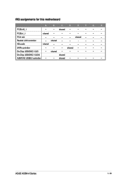
shared - - - shared - - - - - - shared - - - - On Chip USB EHCI 1/2/3/4 shared ASM1042 USB3.0 controller - - Realtek LAN controller - On Chip USB EHCI 1/2/3 - ASUS A55M-A Series 1-19 HD audio shared - - - - - - - shared - - - - - PCIEx1_1 shared - - - - - - - PCI1 slot - - - - shared - - - - - - SATA controller - - - IRQ assignments for this motherboard A B C D E F G H PCIEx16_1 - - shared - - - - -
shared - - - shared - - - - - - shared - - - - On Chip USB EHCI 1/2/3/4 shared ASM1042 USB3.0 controller - - Realtek LAN controller - On Chip USB EHCI 1/2/3 - ASUS A55M-A Series 1-19 HD audio shared - - - - - - - shared - - - - - PCIEx1_1 shared - - - - - - - PCI1 slot - - - - shared - - - - - - SATA controller - - - IRQ assignments for this motherboard A B C D E F G H PCIEx16_1 - - shared - - - - -
A55M-A User's Manual
Page 33
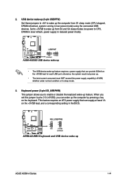
...supply that can provide 500mA on the +5VSB lead, and a corresponding setting in low power mode) using the connected USB devices. A55M-A/USB3 USBPWF 12 23 +5V +5VSB (Default) A55M-A/USB3 USB device wake up • The USB device wake-up . • The total current consumed must NOT exceed the ... 1A on the +5VSB lead for each USB port; 2. KB_USBPWB 12 23 A55M-A/USB3 +5V +5VSB (Default) A55M-A/USB3 Keyboard and USB device wake up the computer from S3 and S4 sleep modes (no power to wake up ASUS A55M-A Series 1-21 USB device wake-up (3-pin USBPFW) Set these jumpers to ...
...supply that can provide 500mA on the +5VSB lead, and a corresponding setting in low power mode) using the connected USB devices. A55M-A/USB3 USBPWF 12 23 +5V +5VSB (Default) A55M-A/USB3 USB device wake up • The USB device wake-up . • The total current consumed must NOT exceed the ... 1A on the +5VSB lead for each USB port; 2. KB_USBPWB 12 23 A55M-A/USB3 +5V +5VSB (Default) A55M-A/USB3 Keyboard and USB device wake up the computer from S3 and S4 sleep modes (no power to wake up ASUS A55M-A Series 1-21 USB device wake-up (3-pin USBPFW) Set these jumpers to ...

A55M-A User's Manual
Page 35
... the ground pin of the connector. CPU FAN PWM CPU FAN IN CPU FAN PWR GND Rotation +12V GND ASUS A55M-A Series 1-23 USB 2.0 ports 11 and 12 (A55M-A only). USB 3.0 ports 11 and 12 (A55M-A/USB3 only). These two 4-pin Universal Serial Bus (USB) ports are for USB 2.0/1.1 devices. 9. USB 2.0 ports... device. This port is HDCP compliant allowing playback of maximum 2A (24 W) fan power. • Only the CPU_FAN connector support the ASUS Fan Xpert feature. 7. This port is for a High-Definition Multimedia Interface (HDMI) connector, and is for connecting USB 3.0 devices.
... the ground pin of the connector. CPU FAN PWM CPU FAN IN CPU FAN PWR GND Rotation +12V GND ASUS A55M-A Series 1-23 USB 2.0 ports 11 and 12 (A55M-A only). USB 3.0 ports 11 and 12 (A55M-A/USB3 only). These two 4-pin Universal Serial Bus (USB) ports are for USB 2.0/1.1 devices. 9. USB 2.0 ports... device. This port is HDCP compliant allowing playback of maximum 2A (24 W) fan power. • Only the CPU_FAN connector support the ASUS Fan Xpert feature. 7. This port is for a High-Definition Multimedia Interface (HDMI) connector, and is for connecting USB 3.0 devices.
A55M-A User's Manual
Page 37
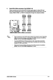
ASUS A55M-A Series 1-25 Serial ATA 3.0 Gb/s connectors (7-pin SATA3G 1~6) These connectors are using Windows® XP SP3 or later version. • When using hot-plug and ... GND SATA3G_3 SATA3G_4 GND RSATA_RXP4 RSATA_RXN4 GND RSATA_TXN4 RSATA_TXP4 GND GND RSATA_RXP3 RSATA_RXN3 GND RSATA_TXN3 RSATA_TXP3 GND A55M-A/USB3 SATA3G_1 SATA3G_2 GND RSATA_RXP1 RSATA_RXN1 GND RSATA_TXN1 RSATA_TXP1 GND GND RSATA_RXP2 RSATA_RXN2 GND RSATA_TXN2 RSATA_TXP2 GND A55M-A/USB3 SATA 3.0Gb/s connectors • These connectors are set the type of the SATA connectors in...
ASUS A55M-A Series 1-25 Serial ATA 3.0 Gb/s connectors (7-pin SATA3G 1~6) These connectors are using Windows® XP SP3 or later version. • When using hot-plug and ... GND SATA3G_3 SATA3G_4 GND RSATA_RXP4 RSATA_RXN4 GND RSATA_TXN4 RSATA_TXP4 GND GND RSATA_RXP3 RSATA_RXN3 GND RSATA_TXN3 RSATA_TXP3 GND A55M-A/USB3 SATA3G_1 SATA3G_2 GND RSATA_RXP1 RSATA_RXN1 GND RSATA_TXN1 RSATA_TXP1 GND GND RSATA_RXP2 RSATA_RXN2 GND RSATA_TXN2 RSATA_TXP2 GND A55M-A/USB3 SATA 3.0Gb/s connectors • These connectors are set the type of the SATA connectors in...
A55M-A User's Manual
Page 39
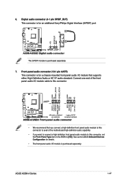
ASUS A55M-A Series 1-27 Front panel audio connector (10-1 pin AAFP) This connector is for a chassis-mounted front panel audio I /O module cable to this connector, set the ... SENSE1_RETUR SENSE2_RETUR AGND NC NC NC MIC2 MICPWR Line out_R NC Line out_L PORT1 L PORT1 R PORT2 R SENSE_SEND PORT2 L A55M-A/USB3 AAFP PIN 1 PIN 1 HD-audio-compliant Legacy AC'97 pin definition compliant definition A55M-A/USB3 Front panel audio connector • We recommend that supports either High Definition Audio or AC`97 audio...
ASUS A55M-A Series 1-27 Front panel audio connector (10-1 pin AAFP) This connector is for a chassis-mounted front panel audio I /O module cable to this connector, set the ... SENSE1_RETUR SENSE2_RETUR AGND NC NC NC MIC2 MICPWR Line out_R NC Line out_L PORT1 L PORT1 R PORT2 R SENSE_SEND PORT2 L A55M-A/USB3 AAFP PIN 1 PIN 1 HD-audio-compliant Legacy AC'97 pin definition compliant definition A55M-A/USB3 Front panel audio connector • We recommend that supports either High Definition Audio or AC`97 audio...
A55M-A User's Manual
Page 41
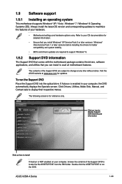
... is enabled in your computer, browse the contents of the Support DVD to change at www.asus.com for reference only. Visit the ASUS website at any time without notice. The following screen is for updates. ASUS A55M-A Series 1-29 Click Drivers, Utilities, Make Disk, Manual, and Contact tabs to your hardware. • Motherboard...
... is enabled in your computer, browse the contents of the Support DVD to change at www.asus.com for reference only. Visit the ASUS website at any time without notice. The following screen is for updates. ASUS A55M-A Series 1-29 Click Drivers, Utilities, Make Disk, Manual, and Contact tabs to your hardware. • Motherboard...
A55M-A User's Manual
Page 44
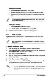
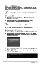
...the Open window, then click Open. 3. Follow the onscreen instructions to complete the updating process. 2.1.2 ASUS EZ Flash 2 The ASUS EZ Flash 2 feature allows you wish to prevent system boot failure! 2-2 ASUS A55M-A Series The ASUS Update utility is done. • This function supports USB flash disks formatted using an OS‑...the latest BIOS file from the Internet a. Press the Up/Down arrow keys to enable it. 3. Go to the Tool menu to select ASUS EZ Flash 2 Utility and press to find the BIOS file, and then press to the Folder Info field. 6. c. Updating from the...
...the Open window, then click Open. 3. Follow the onscreen instructions to complete the updating process. 2.1.2 ASUS EZ Flash 2 The ASUS EZ Flash 2 feature allows you wish to prevent system boot failure! 2-2 ASUS A55M-A Series The ASUS Update utility is done. • This function supports USB flash disks formatted using an OS‑...the latest BIOS file from the Internet a. Press the Up/Down arrow keys to enable it. 3. Go to the Tool menu to select ASUS EZ Flash 2 Utility and press to find the BIOS file, and then press to the Folder Info field. 6. c. Updating from the...
A55M-A User's Manual
Page 46
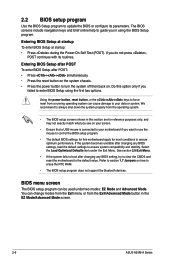
... the USB flash drive with the latest BIOS file and BIOS Updater to a hard disk drive or USB flash drive in DOS environment 1. When the ASUS Logo appears, press to boot using FAT32/16 on the USB flash drive. Please select boot device: SATA: XXXXXXXXXXXXXXXX USB XXXXXXXXXXXXXXXXX UEFI: XXXXXXXXXXXXXXXX Enter Setup... same as shown. NTFS is not supported under DOS environment. Welcome to copy the current BIOS file that you to FreeDOS (http://www.freedos.org)! C:\>d: D:\> 2-4 ASUS A55M-A Series
... the USB flash drive with the latest BIOS file and BIOS Updater to a hard disk drive or USB flash drive in DOS environment 1. When the ASUS Logo appears, press to boot using FAT32/16 on the USB flash drive. Please select boot device: SATA: XXXXXXXXXXXXXXXX USB XXXXXXXXXXXXXXXXX UEFI: XXXXXXXXXXXXXXXX Enter Setup... same as shown. NTFS is not supported under DOS environment. Welcome to copy the current BIOS file that you to FreeDOS (http://www.freedos.org)! C:\>d: D:\> 2-4 ASUS A55M-A Series
A55M-A User's Manual
Page 48
... Setup program. Do this motherboard apply for most conditions to force reset from the Exit/Advanced Mode button in the EZ Mode/Advanced Mode screen. 2-6 ASUS A55M-A Series Refer to section 1.7 Jumpers on your screen. • Ensure that a USB mouse is connected to ensure system compatibility and stability. Select the Load Optimized...
... Setup program. Do this motherboard apply for most conditions to force reset from the Exit/Advanced Mode button in the EZ Mode/Advanced Mode screen. 2-6 ASUS A55M-A Series Refer to section 1.7 Jumpers on your screen. • Ensure that a USB mouse is connected to ensure system compatibility and stability. Select the Load Optimized...

A55M-A User's Manual
Page 50
... bar The menu bar on top of the Advanced Mode. Refer to configure the BIOS settings. To access the EZ Mode, click Exit, then select ASUS EZ Mode. The figure below shows an example of the screen has the following sections for experienced end-users to the following main items: Main... changing the fan settings For changing the system boot configuration For configuring options for special functions For selecting the exit options and loading default settings 2-8 ASUS A55M-A Series
... bar The menu bar on top of the Advanced Mode. Refer to configure the BIOS settings. To access the EZ Mode, click Exit, then select ASUS EZ Mode. The figure below shows an example of the screen has the following sections for experienced end-users to the following main items: Main... changing the fan settings For changing the system boot configuration For configuring options for special functions For selecting the exit options and loading default settings 2-8 ASUS A55M-A Series
A55M-A User's Manual
Page 52
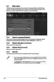
... options. See section 1.7 Jumpers for information on how to clear the BIOS password. After you enter the Advanced Mode of the screen show Installed. 2-10 ASUS A55M-A Series 2.3 Main menu The Main menu screen appears when you set a password, these items show the default Not Installed. The Main menu provides you an...
... options. See section 1.7 Jumpers for information on how to clear the BIOS password. After you enter the Advanced Mode of the screen show Installed. 2-10 ASUS A55M-A Series 2.3 Main menu The Main menu screen appears when you set a password, these items show the default Not Installed. The Main menu provides you an...
A55M-A User's Manual
Page 54
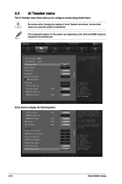
2.4 Ai Tweaker menu The Ai Tweaker menu items allow you installed on the CPU and DIMM model you to configure overclocking-related items. Be cautious when changing the settings of the Ai Tweaker menu items. Incorrect field values can cause the system to display the following items: 2-12 ASUS A55M-A Series The configuration options for this section vary depending on the motherboard. Scroll down to malfunction.
2.4 Ai Tweaker menu The Ai Tweaker menu items allow you installed on the CPU and DIMM model you to configure overclocking-related items. Be cautious when changing the settings of the Ai Tweaker menu items. Incorrect field values can cause the system to display the following items: 2-12 ASUS A55M-A Series The configuration options for this section vary depending on the motherboard. Scroll down to malfunction.


