
A55M-A User's Manual
Page 1
Motherboard A55M-A Series • A55M-A • A55M-A/USB3
Motherboard A55M-A Series • A55M-A • A55M-A/USB3

A55M-A User's Manual
Page 3
Contents Safety information...vi About this guide...vii A55M-A Series specifications summary ix Package contents...xi Product introduction 1.1 Special features 1-1 1.1.1 Product highlights 1-1 1.1.2 ASUS DIGI+ VRM 1-1 1.1.3 ASUS Exclusive Features 1-2 1.2 Before you proceed 1-4 1.3 Motherboard overview 1-5 1.3.1 Placement direction 1-5 1.3.2 Screw holes 1-5 1.3.3 Motherboard layout 1-6 1.3.4 Layout contents 1-7 1.4 Accelerated Processing Unit (APU 1-7 1.4.1 APU installation 1-8 1.4.2 APU heatsink and fan assembly installation 1-9 1.5 System memory 1-11...
Contents Safety information...vi About this guide...vii A55M-A Series specifications summary ix Package contents...xi Product introduction 1.1 Special features 1-1 1.1.1 Product highlights 1-1 1.1.2 ASUS DIGI+ VRM 1-1 1.1.3 ASUS Exclusive Features 1-2 1.2 Before you proceed 1-4 1.3 Motherboard overview 1-5 1.3.1 Placement direction 1-5 1.3.2 Screw holes 1-5 1.3.3 Motherboard layout 1-6 1.3.4 Layout contents 1-7 1.4 Accelerated Processing Unit (APU 1-7 1.4.1 APU installation 1-8 1.4.2 APU heatsink and fan assembly installation 1-9 1.5 System memory 1-11...
A55M-A User's Manual
Page 6
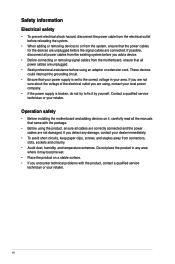
Do not place the product in your retailer. vi Operation safety • Before installing the motherboard and adding devices on a stable surface. • If you detect any area where it may become wet. • Place the product on it by yourself. ... to the correct voltage in any damage, contact your dealer immediately. • To avoid short circuits, keep paper clips, screws, and staples away from the motherboard, ensure that your retailer.
Do not place the product in your retailer. vi Operation safety • Before installing the motherboard and adding devices on a stable surface. • If you detect any area where it may become wet. • Place the product on it by yourself. ... to the correct voltage in any damage, contact your dealer immediately. • To avoid short circuits, keep paper clips, screws, and staples away from the motherboard, ensure that your retailer.
A55M-A User's Manual
Page 7
...motherboard and the new technology it supports. • Chapter 2: BIOS information This chapter tells how to change system settings through the BIOS Setup menus. Refer to the following parts: • Chapter 1: Product introduction This chapter describes the features of the standard package. ASUS websites The ASUS website provides updated information on ASUS... information and for product and software updates. 1. Where to find more information Refer to the ASUS contact information. 2. Optional documentation Your product package may include optional documentation, such as warranty flyers...
...motherboard and the new technology it supports. • Chapter 2: BIOS information This chapter tells how to change system settings through the BIOS Setup menus. Refer to the following parts: • Chapter 1: Product introduction This chapter describes the features of the standard package. ASUS websites The ASUS website provides updated information on ASUS... information and for product and software updates. 1. Where to find more information Refer to the ASUS contact information. 2. Optional documentation Your product package may include optional documentation, such as warranty flyers...
A55M-A User's Manual
Page 11
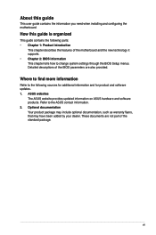
... USB56 USB34 AMD® A55 SATA6G_5 SATA6G_6 SATA6G_3 SATA6G_4 SATA6G_1 SATA6G_2 32Mb BIOS CLRTC SPEAKER F_PANEL EATXPWR ASUS A55M-A Series motherboard User Guide 2 x Serial ATA 3.0 Gb/s cables 1 x I/O Shield User Guide Support DVD • A55M-A Series motherboards include A55M-A and A55M-A/USB3 models. Actual product specifications may vary with different models. Package contents Check your retailer. • The...
... USB56 USB34 AMD® A55 SATA6G_5 SATA6G_6 SATA6G_3 SATA6G_4 SATA6G_1 SATA6G_2 32Mb BIOS CLRTC SPEAKER F_PANEL EATXPWR ASUS A55M-A Series motherboard User Guide 2 x Serial ATA 3.0 Gb/s cables 1 x I/O Shield User Guide Support DVD • A55M-A Series motherboards include A55M-A and A55M-A/USB3 models. Actual product specifications may vary with different models. Package contents Check your retailer. • The...
A55M-A User's Manual
Page 13
... and accelerated data transfer rates of applications, from gaming to assure unmitigated performance, ASUS A55 boards with DIGI+ VRM remain efficient and accurate for the APU* ASUS motherboards using userdefined profiles. The APU voltage is that DIGI+ VRM technology ensures better energy... / 1600 / 1333 / 1066 MHz Support This motherboard supports dual-channel DDR3 memory with AMD® Radeon™ HD 7000 series graphics. This revolutionary APU (Accelerated Processing Unit) combines processing power and advanced DirectX 11 graphics in FM2 socket compatible CPUs ASUS A55M-A Series 1-1
... and accelerated data transfer rates of applications, from gaming to assure unmitigated performance, ASUS A55 boards with DIGI+ VRM remain efficient and accurate for the APU* ASUS motherboards using userdefined profiles. The APU voltage is that DIGI+ VRM technology ensures better energy... / 1600 / 1333 / 1066 MHz Support This motherboard supports dual-channel DDR3 memory with AMD® Radeon™ HD 7000 series graphics. This revolutionary APU (Accelerated Processing Unit) combines processing power and advanced DirectX 11 graphics in FM2 socket compatible CPUs ASUS A55M-A Series 1-1
A55M-A User's Manual
Page 14
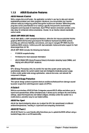
... cool computing environment. It offers a total system-wide energy optimization, reduces fan noise, and extends the component's lifespan. ASUS Fan Xpert ASUS Fan Xpert intelligently allows you to launch and operate these utilities simultaneously. It allows you with more flexibility, convenience, and ... surges from switching power supply unit (PSU). Overall, it's an intuitive network bandwidth control center. ASUS Anti-Surge Protection This special design protects expensive devices and the motherboard from damage caused by configuring profiles through the inuitive user interface.
... cool computing environment. It offers a total system-wide energy optimization, reduces fan noise, and extends the component's lifespan. ASUS Fan Xpert ASUS Fan Xpert intelligently allows you to launch and operate these utilities simultaneously. It allows you with more flexibility, convenience, and ... surges from switching power supply unit (PSU). Overall, it's an intuitive network bandwidth control center. ASUS Anti-Surge Protection This special design protects expensive devices and the motherboard from damage caused by configuring profiles through the inuitive user interface.

A55M-A User's Manual
Page 16
...that the system is ON, in sleep mode, or in any motherboard component. A55M-A/USB3 SB_PWR ON OFF Standby Power Powered Off A55M-A/USB3 Onboard LED 1-4 Chapter 1: Product introduction Standby Power LED The motherboard comes with a standby power LED that lights up to indicate ... static electricity. • Hold components by the edges to the motherboard, peripherals, or components. The illustration below shows the location of the following precautions before you install motherboard components or change any motherboard settings. • Unplug the power cord from the wall socket...
...that the system is ON, in sleep mode, or in any motherboard component. A55M-A/USB3 SB_PWR ON OFF Standby Power Powered Off A55M-A/USB3 Onboard LED 1-4 Chapter 1: Product introduction Standby Power LED The motherboard comes with a standby power LED that lights up to indicate ... static electricity. • Hold components by the edges to the motherboard, peripherals, or components. The illustration below shows the location of the following precautions before you install motherboard components or change any motherboard settings. • Unplug the power cord from the wall socket...
A55M-A User's Manual
Page 17
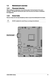
Place this side towards the rear of the chassis as indicated in the image below. 1.3.2 Screw holes Place six screws into the chassis in the correct orientation. 1.3 Motherboard overview 1.3.1 Placement direction When installing the motherboard, ensure that you place it into the holes indicated by circles to secure the motherboard to the rear part of the chassis. The edge with external ports goes to the chassis. Doing so can damage the motherboard. A55M-A/USB3 ASUS A55M-A Series 1-5 DO NOT overtighten the screws!
Place this side towards the rear of the chassis as indicated in the image below. 1.3.2 Screw holes Place six screws into the chassis in the correct orientation. 1.3 Motherboard overview 1.3.1 Placement direction When installing the motherboard, ensure that you place it into the holes indicated by circles to secure the motherboard to the rear part of the chassis. The edge with external ports goes to the chassis. Doing so can damage the motherboard. A55M-A/USB3 ASUS A55M-A Series 1-5 DO NOT overtighten the screws!
A55M-A User's Manual
Page 18
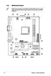
1.3.3 Motherboard layout A55M-A Series motherboards include A55M-A and A55M-A/USB3 models. The package contents vary between models. The layout illustrations in this user guide are for A55MA/USB3 only. 1 2 3 4 5 18.8cm(7.4in) KBMS ... DIMM_A1 (64bit, 240-pin module) DDR3 DIMM_B1 (64bit, 240-pin module) SOCKET FM2 DVI_VGA USB1112 23.6cm(9.3in) LAN1_USB12 ASM 1042 EATXPWR KB_USBWB AUDIO 2 A55M-A/USB3 PCIEX16 RTL 8111F Super I/O PCIEX1_1 BATTERY PCI1 SATA6G_5 SATA6G_6 AMD® A55 SATA6G_3 SATA6G_4 6 SB_PWR ALC 887 SPDIF_OUT AAFP SATA6G_1 SATA6G_2 USBPWF 32Mb BIOS...
1.3.3 Motherboard layout A55M-A Series motherboards include A55M-A and A55M-A/USB3 models. The package contents vary between models. The layout illustrations in this user guide are for A55MA/USB3 only. 1 2 3 4 5 18.8cm(7.4in) KBMS ... DIMM_A1 (64bit, 240-pin module) DDR3 DIMM_B1 (64bit, 240-pin module) SOCKET FM2 DVI_VGA USB1112 23.6cm(9.3in) LAN1_USB12 ASM 1042 EATXPWR KB_USBWB AUDIO 2 A55M-A/USB3 PCIEX16 RTL 8111F Super I/O PCIEX1_1 BATTERY PCI1 SATA6G_5 SATA6G_6 AMD® A55 SATA6G_3 SATA6G_4 6 SB_PWR ALC 887 SPDIF_OUT AAFP SATA6G_1 SATA6G_2 USBPWF 32Mb BIOS...

A55M-A User's Manual
Page 19
... USB56, USB34) 11. Standby power LED (SB_PWR) Page 1-21 1-24 1-7 1-23 1-11 1-25 1-26 1-26 1-20 1-28 1-21 1-27 1-27 1-4 1.4 Accelerated Processing Unit (APU) This motherboard comes with an FM2 socket designed for the FM2 socket. DO NOT force the APU into the socket to prevent bending the pins and damaging... CPU_FAN) and Chassis fan connector (3-pin CHA_FAN) 5. Digital audio connector (4-1 pin SPDIF_OUT) 13. SATA 3.0Gb/s connectors (7-pin SATA3G_1~6) 7. Keyboard power (3-pin KB_USBPWB) 2. DDR3 DIMM slots 6. A55M-A/USB3 A55M-A/USB3 CPU socket FM2 ASUS A55M-A Series 1-7
... USB56, USB34) 11. Standby power LED (SB_PWR) Page 1-21 1-24 1-7 1-23 1-11 1-25 1-26 1-26 1-20 1-28 1-21 1-27 1-27 1-4 1.4 Accelerated Processing Unit (APU) This motherboard comes with an FM2 socket designed for the FM2 socket. DO NOT force the APU into the socket to prevent bending the pins and damaging... CPU_FAN) and Chassis fan connector (3-pin CHA_FAN) 5. Digital audio connector (4-1 pin SPDIF_OUT) 13. SATA 3.0Gb/s connectors (7-pin SATA3G_1~6) 7. Keyboard power (3-pin KB_USBPWB) 2. DDR3 DIMM slots 6. A55M-A/USB3 A55M-A/USB3 CPU socket FM2 ASUS A55M-A Series 1-7

A55M-A User's Manual
Page 23
DDR3 modules are developed for better performance with two Double Data Rate 3 (DDR3) Dual Inline Memory Modules (DIMM) sockets. The figure illustrates the location of the DDR3 DIMM sockets: DIMM_A1 DIMM_B1 A55M-A/USB3 Channel Channel A Channel B A55M-A/USB3 240-pin DDR3 DIMM sockets Sockets DIMM_A1 DIMM_B1 ASUS A55M-A Series 1-11 1.5 System memory 1.5.1 Overview This motherboard comes with less power consumption. A DDR3 module has the same physical dimensions as a DDR2 DIMM but is notched differently to prevent installation on a DDR2 DIMM socket.
DDR3 modules are developed for better performance with two Double Data Rate 3 (DDR3) Dual Inline Memory Modules (DIMM) sockets. The figure illustrates the location of the DDR3 DIMM sockets: DIMM_A1 DIMM_B1 A55M-A/USB3 Channel Channel A Channel B A55M-A/USB3 240-pin DDR3 DIMM sockets Sockets DIMM_A1 DIMM_B1 ASUS A55M-A Series 1-11 1.5 System memory 1.5.1 Overview This motherboard comes with less power consumption. A DDR3 module has the same physical dimensions as a DDR2 DIMM but is notched differently to prevent installation on a DDR2 DIMM socket.
A55M-A User's Manual
Page 24
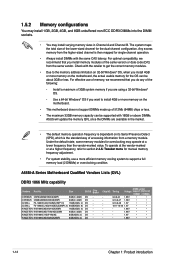
... - For optimal compatibility, we recommend that you install 4GB or more memory on the motherboard, the actual usable memory for the OS can be about 3GB or less. To operate... use a more efficient memory cooling system to support a full memory load (2 DIMMs) or overclocking condition. A55M-A Series Motherboard Qualified Vendors Lists (QVL) DDR3 1866 MHz capability Vendors Part No. Timing DIMM socket Voltage support (Optional)...® OS if you want to install 4GB or more memory on the motherboard. • This motherboard does not support DIMMs made up of 512Mb (64MB) chips or less. ...
... - For optimal compatibility, we recommend that you install 4GB or more memory on the motherboard, the actual usable memory for the OS can be about 3GB or less. To operate... use a more efficient memory cooling system to support a full memory load (2 DIMMs) or overclocking condition. A55M-A Series Motherboard Qualified Vendors Lists (QVL) DDR3 1866 MHz capability Vendors Part No. Timing DIMM socket Voltage support (Optional)...® OS if you want to install 4GB or more memory on the motherboard. • This motherboard does not support DIMMs made up of 512Mb (64MB) chips or less. ...
A55M-A User's Manual
Page 30
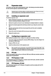
...cards such as a LAN card, SCSI card, USB card, and other cards that comply with PCI specifications. 1.6.4 PCI Express x1 slot This motherboard supports PCI Express x1 network cards, SCSI cards, and other cards that comply with the screw you may cause you intend to install expansion ... When using PCI cards on the slot. 5. Secure the card to the chassis with the PCI Express specifications. 1.6.5 PCI Express x16 slot This motherboard supports one PCI Express x16 graphics card that they support. See Chapter 2 for the expansion card. Assign an IRQ to do not need to use...
...cards such as a LAN card, SCSI card, USB card, and other cards that comply with PCI specifications. 1.6.4 PCI Express x1 slot This motherboard supports PCI Express x1 network cards, SCSI cards, and other cards that comply with the screw you may cause you intend to install expansion ... When using PCI cards on the slot. 5. Secure the card to the chassis with the PCI Express specifications. 1.6.5 PCI Express x16 slot This motherboard supports one PCI Express x16 graphics card that they support. See Chapter 2 for the expansion card. Assign an IRQ to do not need to use...
A55M-A User's Manual
Page 31
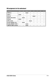
Realtek LAN controller - shared - - - - - IRQ assignments for this motherboard A B C D E F G H PCIEx16_1 - - shared - - - - - - shared - - - ASUS A55M-A Series 1-19 PCI1 slot - - - - HD audio shared - - - - - - - shared - - - - On Chip USB EHCI 1/2/3/4 shared ASM1042 USB3.0 controller - - PCIEx1_1 shared - - - - - - - shared - - - - - - SATA controller - - - On Chip USB EHCI 1/2/3 - shared - - - - -
Realtek LAN controller - shared - - - - - IRQ assignments for this motherboard A B C D E F G H PCIEx16_1 - - shared - - - - - - shared - - - ASUS A55M-A Series 1-19 PCI1 slot - - - - HD audio shared - - - - - - - shared - - - - On Chip USB EHCI 1/2/3/4 shared ASM1042 USB3.0 controller - - PCIEx1_1 shared - - - - - - - shared - - - - - - SATA controller - - - On Chip USB EHCI 1/2/3 - shared - - - - -

A55M-A User's Manual
Page 35
...DVI-I 10. CPU FAN PWM CPU FAN IN CPU FAN PWR GND Rotation +12V GND ASUS A55M-A Series 1-23 This port is for any DVI-D compatible device. Insufficient air flow inside the system may damage the motherboard components. DVI-D port. These are for USB 2.0/1.1 devices. 8. DVI-D can't be converted... to output RGB signal to the fan connectors. DO NOT place jumper caps on the motherboard, ensuring that the black wire of each cable matches the ground pin of maximum 2A (24 W) fan power. • Only the CPU_FAN connector ...
...DVI-I 10. CPU FAN PWM CPU FAN IN CPU FAN PWR GND Rotation +12V GND ASUS A55M-A Series 1-23 This port is for any DVI-D compatible device. Insufficient air flow inside the system may damage the motherboard components. DVI-D port. These are for USB 2.0/1.1 devices. 8. DVI-D can't be converted... to output RGB signal to the fan connectors. DO NOT place jumper caps on the motherboard, ensuring that the black wire of each cable matches the ground pin of maximum 2A (24 W) fan power. • Only the CPU_FAN connector ...
A55M-A User's Manual
Page 39
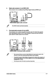
ASUS A55M-A Series 1-27 Front panel audio connector (10-1 pin AAFP) This connector is for details. • The front panel audio I /O module cable to this connector, set the Front Panel Type item in the BIOS to this connector. Connect one end of the motherboard high-definition audio ...NC MIC2 MICPWR Line out_R NC Line out_L PORT1 L PORT1 R PORT2 R SENSE_SEND PORT2 L A55M-A/USB3 AAFP PIN 1 PIN 1 HD-audio-compliant Legacy AC'97 pin definition compliant definition A55M-A/USB3 Front panel audio connector • We recommend that supports either High Definition Audio or ...
ASUS A55M-A Series 1-27 Front panel audio connector (10-1 pin AAFP) This connector is for details. • The front panel audio I /O module cable to this connector, set the Front Panel Type item in the BIOS to this connector. Connect one end of the motherboard high-definition audio ...NC MIC2 MICPWR Line out_R NC Line out_L PORT1 L PORT1 R PORT2 R SENSE_SEND PORT2 L A55M-A/USB3 AAFP PIN 1 PIN 1 HD-audio-compliant Legacy AC'97 pin definition compliant definition A55M-A/USB3 Front panel audio connector • We recommend that supports either High Definition Audio or ...

A55M-A User's Manual
Page 40
... 1-28 Chapter 1: Product introduction USB56 USB34 USB+5V USB_P6USB_P6+ GND NC USB+5V USB_P4USB_P4+ GND NC A55M-A/USB3 PIN 1 PIN 1 USB+5V USB_P5USB_P5+ GND USB+5V USB_P3USB_P3+ GND A55M-A/USB3 USB2.0 connectors Never connect a 1394 cable to a slot opening at the back of the system ...chassis. USB 2.0 connectors (10-1 pin USB56, USB34) These connectors are for USB 2.0 ports. Doing so will damage the motherboard! These USB connectors comply with...
... 1-28 Chapter 1: Product introduction USB56 USB34 USB+5V USB_P6USB_P6+ GND NC USB+5V USB_P4USB_P4+ GND NC A55M-A/USB3 PIN 1 PIN 1 USB+5V USB_P5USB_P5+ GND USB+5V USB_P3USB_P3+ GND A55M-A/USB3 USB2.0 connectors Never connect a 1394 cable to a slot opening at the back of the system ...chassis. USB 2.0 connectors (10-1 pin USB56, USB34) These connectors are for USB 2.0 ports. Doing so will damage the motherboard! These USB connectors comply with...
A55M-A User's Manual
Page 41
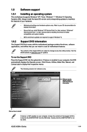
..., and utilities that you can install to maximize the features of your hardware. • Motherboard settings and hardware options vary. Visit the ASUS website at any time without notice. ASUS A55M-A Series 1-29 Click an icon to display Support DVD/motherboard information Click an item to install If Autorun is NOT enabled on your computer...
..., and utilities that you can install to maximize the features of your hardware. • Motherboard settings and hardware options vary. Visit the ASUS website at any time without notice. ASUS A55M-A Series 1-29 Click an icon to display Support DVD/motherboard information Click an item to install If Autorun is NOT enabled on your computer...
A55M-A User's Manual
Page 43
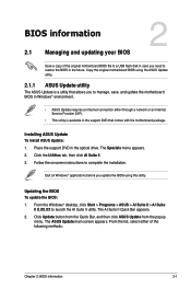
... is available in the support DVD that allows you to manage, save, and update the motherboard BIOS in Windows® environment. • ASUS Update requires an Internet connection either of the original motherboard BIOS file to a USB flash disk in case you need to restore the BIOS in the optical ...drive. Place the support DVD in the future. From the Windows® desktop, click Start > Programs > ASUS > AI Suite II > AI Suite II ...
... is available in the support DVD that allows you to manage, save, and update the motherboard BIOS in Windows® environment. • ASUS Update requires an Internet connection either of the original motherboard BIOS file to a USB flash disk in case you need to restore the BIOS in the optical ...drive. Place the support DVD in the future. From the Windows® desktop, click Start > Programs > ASUS > AI Suite II > AI Suite II ...


