
A55M-A User's Manual
Page 3
Contents Safety information...vi About this guide...vii A55M-A Series specifications summary ix Package contents...xi Product introduction 1.1 Special features 1-1 1.1.1 Product highlights 1-1 1.1.2 ASUS DIGI+ VRM 1-1 1.1.3 ASUS Exclusive Features 1-2 1.2 Before you proceed 1-4 1.3 Motherboard overview 1-5 1.3.1 Placement direction 1-5 1.3.2 Screw holes...1.6.5 PCI Express x16 slot 1-18 1.7 Jumpers...1-20 1.8 Connectors 1-22 1.8.1 Rear panel ports 1-22 1.8.2 Internal connectors 1-23 1.9 Software support 1-29 1.9.1 Installing an operating system 1-29 1.9.2 Support DVD information 1-29 ...
Contents Safety information...vi About this guide...vii A55M-A Series specifications summary ix Package contents...xi Product introduction 1.1 Special features 1-1 1.1.1 Product highlights 1-1 1.1.2 ASUS DIGI+ VRM 1-1 1.1.3 ASUS Exclusive Features 1-2 1.2 Before you proceed 1-4 1.3 Motherboard overview 1-5 1.3.1 Placement direction 1-5 1.3.2 Screw holes...1.6.5 PCI Express x16 slot 1-18 1.7 Jumpers...1-20 1.8 Connectors 1-22 1.8.1 Rear panel ports 1-22 1.8.2 Internal connectors 1-23 1.9 Software support 1-29 1.9.1 Installing an operating system 1-29 1.9.2 Support DVD information 1-29 ...
A55M-A User's Manual
Page 6
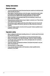
... prevent electrical shock hazard, disconnect the power cable from the electrical outlet before relocating the system. • When adding or removing devices to or from connectors, slots, sockets and circuitry. • Avoid dust, humidity, and temperature extremes. If you are not sure about the voltage of the electrical outlet you detect...
... prevent electrical shock hazard, disconnect the power cable from the electrical outlet before relocating the system. • When adding or removing devices to or from connectors, slots, sockets and circuitry. • Avoid dust, humidity, and temperature extremes. If you are not sure about the voltage of the electrical outlet you detect...
A55M-A User's Manual
Page 9
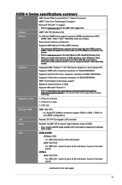
...USB A55M-A/USB3 ASMedia 1042 - 2 x USB 3.0/2.0 ports at the back panel AMD® A55 FCH: - 6 x USB 2.0/1.1 ports (4 ports at the mid-board, 2 ports at the back panel) A55M-A AMD...® A55 FCH: - 8 x USB 2.0/1.1 ports (4 ports at the mid-board, 4 ports at the back panel) (continued on the next page) ix Expansion slots 1 x PCIe 2.0 x16 slot 1 x PCIe 2.0 x1 slots 1 x PCI slot Storage / RAID AMD® A55 FCH: - 6 x Serial ATA 3.0Gb/s connectors... of 2560x1600@60Hz Supports D-Sub with 16GB or above DIMMs. ASUS will update the memory QVL once the DIMMs are using a Windows...
...USB A55M-A/USB3 ASMedia 1042 - 2 x USB 3.0/2.0 ports at the back panel AMD® A55 FCH: - 6 x USB 2.0/1.1 ports (4 ports at the mid-board, 2 ports at the back panel) A55M-A AMD...® A55 FCH: - 8 x USB 2.0/1.1 ports (4 ports at the mid-board, 4 ports at the back panel) (continued on the next page) ix Expansion slots 1 x PCIe 2.0 x16 slot 1 x PCIe 2.0 x1 slots 1 x PCI slot Storage / RAID AMD® A55 FCH: - 6 x Serial ATA 3.0Gb/s connectors... of 2560x1600@60Hz Supports D-Sub with 16GB or above DIMMs. ASUS will update the memory QVL once the DIMMs are using a Windows...
A55M-A User's Manual
Page 10
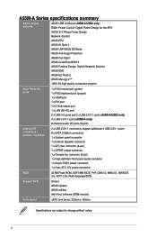
... ASUS ESD ASUS EZ Flash 2 ASUS MyLogo 2™ 100% All high-quality conductive polymer Back Panel I/O ports 1 x PS/2 mouse port (green) 1 x PS/2 keyboard port (purple) 1 x HDMI port 1 x DVI port 1 x D-Sub output port 1 x LAN (RJ-45) port 2 x USB 3.0 ports and 2 x USB 2.0/1.1 ports (A55M-A/USB3 only) 4 x USB 2.0/1.1 ports (A55M-A only) 8-channel audio I/O ports (3-jack) Internal I/O connectors / buttons / switches 2 x USB 2.0/1.1 connectors...
... ASUS ESD ASUS EZ Flash 2 ASUS MyLogo 2™ 100% All high-quality conductive polymer Back Panel I/O ports 1 x PS/2 mouse port (green) 1 x PS/2 keyboard port (purple) 1 x HDMI port 1 x DVI port 1 x D-Sub output port 1 x LAN (RJ-45) port 2 x USB 3.0 ports and 2 x USB 2.0/1.1 ports (A55M-A/USB3 only) 4 x USB 2.0/1.1 ports (A55M-A only) 8-channel audio I/O ports (3-jack) Internal I/O connectors / buttons / switches 2 x USB 2.0/1.1 connectors...

A55M-A User's Manual
Page 19
...-pin EATXPWR, 4-pin ATX12V) 3. Front panel audio connector (10-1 pin AAFP) 14. The APU fits in only one correct orientation. A55M-A/USB3 A55M-A/USB3 CPU socket FM2 ASUS A55M-A Series 1-7 Speaker connector (4-pin SPEAKER) 9. USB device wake-up (3-pin USBPWF) 12. Ensure that you use a APU designed for AMD® A-series accelerated processors with AMD® Radeon&#...
...-pin EATXPWR, 4-pin ATX12V) 3. Front panel audio connector (10-1 pin AAFP) 14. The APU fits in only one correct orientation. A55M-A/USB3 A55M-A/USB3 CPU socket FM2 ASUS A55M-A Series 1-7 Speaker connector (4-pin SPEAKER) 9. USB device wake-up (3-pin USBPWF) 12. Ensure that you use a APU designed for AMD® A-series accelerated processors with AMD® Radeon&#...
A55M-A User's Manual
Page 30
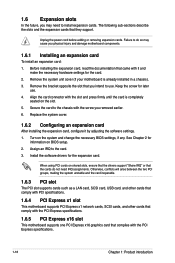
... necessary BIOS settings, if any. When using PCI cards on the slot. 5. Unplug the power cord before adding or removing expansion cards. Align the card connector with it by adjusting the software settings. 1. Replace the system cover. 1.6.2 Configuring an expansion card After installing the expansion card, configure it and make the...
... necessary BIOS settings, if any. When using PCI cards on the slot. 5. Unplug the power cord before adding or removing expansion cards. Align the card connector with it by adjusting the software settings. 1. Replace the system cover. 1.6.2 Configuring an expansion card After installing the expansion card, configure it and make the...

A55M-A User's Manual
Page 34
...). This port connects to a Local Area Network (LAN) through a network hub. This port connects to the tape, CD, DVD player, or other VGA-compatible devices. 3. 1.8 1.8.1 1 Connectors Rear panel ports 2 3 45 11 10 9 8 7 6 1. Video Graphics Adapter (VGA) port. LAN port LED indications Activity/Link LED Status Description OFF No link ORANGE Linked...
...). This port connects to a Local Area Network (LAN) through a network hub. This port connects to the tape, CD, DVD player, or other VGA-compatible devices. 3. 1.8 1.8.1 1 Connectors Rear panel ports 2 3 45 11 10 9 8 7 6 1. Video Graphics Adapter (VGA) port. LAN port LED indications Activity/Link LED Status Description OFF No link ORANGE Linked...

A55M-A User's Manual
Page 35
... CPU_FAN, and 3-pin CHA_FAN) Connect the fan cables to the fan connectors on the fan connectors. • The CPU_FAN connector supports a CPU fan of maximum 2A (24 W) fan power. • Only the CPU_FAN connector support the ASUS Fan Xpert feature. CPU_FAN CHA_FAN A55M-A/USB3 A55M-A/USB3 CPU fan connector DO NOT forget to connect the fan cables to CRT and...
... CPU_FAN, and 3-pin CHA_FAN) Connect the fan cables to the fan connectors on the fan connectors. • The CPU_FAN connector supports a CPU fan of maximum 2A (24 W) fan power. • Only the CPU_FAN connector support the ASUS Fan Xpert feature. CPU_FAN CHA_FAN A55M-A/USB3 A55M-A/USB3 CPU fan connector DO NOT forget to connect the fan cables to CRT and...

A55M-A User's Manual
Page 36
...+12 Volts +12 Volts +5V Standby Power OK PIN 1 GND +5 Volts GND +5 Volts GND +3 Volts +3 Volts PIN 1 A55M-A/USB3 ATX power connectors GND +5 Volts +5 Volts +5 Volts -5 Volts GND GND GND PSON# GND -12 Volts +3 Volts • We recommend that the... may become unstable or may not boot up if the power is inadequate. • DO NOT forget to fit these connectors in only one orientation. 2. Otherwise, the system will not boot up. • We recommend that you intend to use...pin power plugs, ensure that the 20-pin power plug can provide at http://support.asus.
...+12 Volts +12 Volts +5V Standby Power OK PIN 1 GND +5 Volts GND +5 Volts GND +3 Volts +3 Volts PIN 1 A55M-A/USB3 ATX power connectors GND +5 Volts +5 Volts +5 Volts -5 Volts GND GND GND PSON# GND -12 Volts +3 Volts • We recommend that the... may become unstable or may not boot up if the power is inadequate. • DO NOT forget to fit these connectors in only one orientation. 2. Otherwise, the system will not boot up. • We recommend that you intend to use...pin power plugs, ensure that the 20-pin power plug can provide at http://support.asus.
A55M-A User's Manual
Page 37
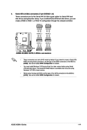
...RSATA_TXN4 RSATA_TXP4 GND GND RSATA_RXP3 RSATA_RXN3 GND RSATA_TXN3 RSATA_TXP3 GND A55M-A/USB3 SATA3G_1 SATA3G_2 GND RSATA_RXP1 RSATA_RXN1 GND RSATA_TXN1 RSATA_TXP1 GND GND RSATA_RXP2 RSATA_RXN2 GND RSATA_TXN2 RSATA_TXP2 GND A55M-A/USB3 SATA 3.0Gb/s connectors • These connectors are set to [AHCI]. The Serial ATA RAID ... You must install Windows® XP Service Pack 3 or later version before using these connectors, set the type of the SATA connectors in the BIOS to AHCI mode by default. ASUS A55M-A Series 1-25 If you can create a RAID 0, RAID 1, or RAID 10 configuration...
...RSATA_TXN4 RSATA_TXP4 GND GND RSATA_RXP3 RSATA_RXN3 GND RSATA_TXN3 RSATA_TXP3 GND A55M-A/USB3 SATA3G_1 SATA3G_2 GND RSATA_RXP1 RSATA_RXN1 GND RSATA_TXN1 RSATA_TXP1 GND GND RSATA_RXP2 RSATA_RXN2 GND RSATA_TXN2 RSATA_TXP2 GND A55M-A/USB3 SATA 3.0Gb/s connectors • These connectors are set to [AHCI]. The Serial ATA RAID ... You must install Windows® XP Service Pack 3 or later version before using these connectors, set the type of the SATA connectors in the BIOS to AHCI mode by default. ASUS A55M-A Series 1-25 If you can create a RAID 0, RAID 1, or RAID 10 configuration...
A55M-A User's Manual
Page 38
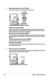
... system power LED. Connect the chassis power LED cable to hear system beeps and warnings. +5V GND GND Speaker Out A55M-A/USB3 SPEAKER PIN 1 A55M-A/USB3 Speaker Out Connector 1-26 Chapter 1: Product introduction Speaker connector (4-pin SPEAKER) The 4-pin connector is for the chassis-mounted system warning speaker. 4. The IDE LED lights up when you to this...
... system power LED. Connect the chassis power LED cable to hear system beeps and warnings. +5V GND GND Speaker Out A55M-A/USB3 SPEAKER PIN 1 A55M-A/USB3 Speaker Out Connector 1-26 Chapter 1: Product introduction Speaker connector (4-pin SPEAKER) The 4-pin connector is for the chassis-mounted system warning speaker. 4. The IDE LED lights up when you to this...
A55M-A User's Manual
Page 39
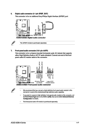
... in the BIOS to this connector. 6. ASUS A55M-A Series 1-27 Digital audio connector (4-1 pin SPDIF_OUT) This connector is for a chassis-mounted front panel audio I /O module cable to [HD]. Front panel audio connector (10-1 pin AAFP) This connector is for an additional Sony/Philips Digital Interface (S/PDIF) port. +5V SPDIFOUT GND A55M-A/USB3 SPDIF_OUT A55M-A/USB3 Digital audio connector The S/PDIF module is...
... in the BIOS to this connector. 6. ASUS A55M-A Series 1-27 Digital audio connector (4-1 pin SPDIF_OUT) This connector is for a chassis-mounted front panel audio I /O module cable to [HD]. Front panel audio connector (10-1 pin AAFP) This connector is for an additional Sony/Philips Digital Interface (S/PDIF) port. +5V SPDIFOUT GND A55M-A/USB3 SPDIF_OUT A55M-A/USB3 Digital audio connector The S/PDIF module is...

A55M-A User's Manual
Page 40
... with USB 2.0 specification that supports up to the USB connectors. USB56 USB34 USB+5V USB_P6USB_P6+ GND NC USB+5V USB_P4USB_P4+ GND NC A55M-A/USB3 PIN 1 PIN 1 USB+5V USB_P5USB_P5+ GND USB+5V USB_P3USB_P3+ GND A55M-A/USB3 USB2.0 connectors Never connect a 1394 cable to 480Mbps connection speed. 8. The USB 2.0 module is purchased separately. 1-28 Chapter 1: Product introduction...
... with USB 2.0 specification that supports up to the USB connectors. USB56 USB34 USB+5V USB_P6USB_P6+ GND NC USB+5V USB_P4USB_P4+ GND NC A55M-A/USB3 PIN 1 PIN 1 USB+5V USB_P5USB_P5+ GND USB+5V USB_P3USB_P3+ GND A55M-A/USB3 USB2.0 connectors Never connect a 1394 cable to 480Mbps connection speed. 8. The USB 2.0 module is purchased separately. 1-28 Chapter 1: Product introduction...
A55M-A User's Manual
Page 62
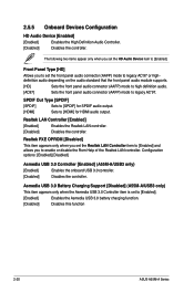
...or disable the Rom Help of the Realtek LAN controller. Asmedia USB 3.0 Battery Charging Support [Disabled] (A55M-A/USB3 only) This item appears only when the Asmedia USB 3.0 Controller item is set the HD Audio Device...A55M-A/USB3 only) [Enabled] Enables the onboard USB 3.0 controller. [Disabled] Disables the controller. Realtek PXE OPROM [Disabled] This item appears only when you set the Realtek LAN Controller item to [Enabled] and allows you to set the front panel audio connector... USB 3.0 battery charging function. [Disabled] Disables this function 2-20 ASUS A55M-A Series
...or disable the Rom Help of the Realtek LAN controller. Asmedia USB 3.0 Battery Charging Support [Disabled] (A55M-A/USB3 only) This item appears only when the Asmedia USB 3.0 Controller item is set the HD Audio Device...A55M-A/USB3 only) [Enabled] Enables the onboard USB 3.0 controller. [Disabled] Disables the controller. Realtek PXE OPROM [Disabled] This item appears only when you set the Realtek LAN Controller item to [Enabled] and allows you to set the front panel audio connector... USB 3.0 battery charging function. [Disabled] Disables this function 2-20 ASUS A55M-A Series


