
A55M-A User's Manual
Page 3
Contents Safety information...vi About this guide...vii A55M-A Series specifications summary ix Package contents...xi Product introduction 1.1 Special features 1-1 1.1.1 Product highlights 1-1 1.1.2 ASUS DIGI+ VRM 1-1 1.1.3 ASUS Exclusive Features 1-2 1.2 Before you proceed 1-4 1.3 Motherboard overview 1-5 1.3.1 Placement direction 1-5 1.3.2 Screw holes...1.6.5 PCI Express x16 slot 1-18 1.7 Jumpers...1-20 1.8 Connectors 1-22 1.8.1 Rear panel ports 1-22 1.8.2 Internal connectors 1-23 1.9 Software support 1-29 1.9.1 Installing an operating system 1-29 1.9.2 Support DVD information 1-29 ...
Contents Safety information...vi About this guide...vii A55M-A Series specifications summary ix Package contents...xi Product introduction 1.1 Special features 1-1 1.1.1 Product highlights 1-1 1.1.2 ASUS DIGI+ VRM 1-1 1.1.3 ASUS Exclusive Features 1-2 1.2 Before you proceed 1-4 1.3 Motherboard overview 1-5 1.3.1 Placement direction 1-5 1.3.2 Screw holes...1.6.5 PCI Express x16 slot 1-18 1.7 Jumpers...1-20 1.8 Connectors 1-22 1.8.1 Rear panel ports 1-22 1.8.2 Internal connectors 1-23 1.9 Software support 1-29 1.9.1 Installing an operating system 1-29 1.9.2 Support DVD information 1-29 ...
A55M-A User's Manual
Page 6
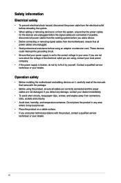
... prevent electrical shock hazard, disconnect the power cable from the electrical outlet before relocating the system. • When adding or removing devices to or from connectors, slots, sockets and circuitry. • Avoid dust, humidity, and temperature extremes. vi If possible, disconnect all power cables from the existing system before you are...
... prevent electrical shock hazard, disconnect the power cable from the electrical outlet before relocating the system. • When adding or removing devices to or from connectors, slots, sockets and circuitry. • Avoid dust, humidity, and temperature extremes. vi If possible, disconnect all power cables from the existing system before you are...
A55M-A User's Manual
Page 9
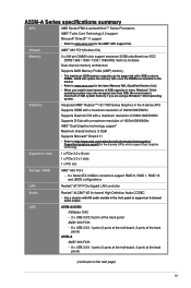
... or more, Windows® 32-bit operating system may only recognize less than 3GB. USB A55M-A/USB3 ASMedia 1042 - 2 x USB 3.0/2.0 ports at the back panel AMD® A55 FCH: -... maximum 32GB memory capacity can be supported with HD audio module in the market. • Refer to www.asus.com for the AMD® APU support list. Expansion slots 1 x PCIe 2.0 x16 slot 1 x PCIe...slots 1 x PCI slot Storage / RAID AMD® A55 FCH: - 6 x Serial ATA 3.0Gb/s connectors support RAID 0, RAID 1, RAID 10 and JBOD configurations LAN Realtek® 8111F PCIe Gigabit LAN controller Audio Realtek...
... or more, Windows® 32-bit operating system may only recognize less than 3GB. USB A55M-A/USB3 ASMedia 1042 - 2 x USB 3.0/2.0 ports at the back panel AMD® A55 FCH: -... maximum 32GB memory capacity can be supported with HD audio module in the market. • Refer to www.asus.com for the AMD® APU support list. Expansion slots 1 x PCIe 2.0 x16 slot 1 x PCIe...slots 1 x PCI slot Storage / RAID AMD® A55 FCH: - 6 x Serial ATA 3.0Gb/s connectors support RAID 0, RAID 1, RAID 10 and JBOD configurations LAN Realtek® 8111F PCIe Gigabit LAN controller Audio Realtek...
A55M-A User's Manual
Page 10
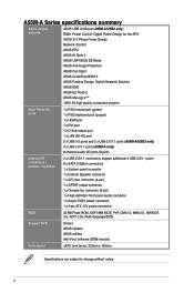
... ASUS ESD ASUS EZ Flash 2 ASUS MyLogo 2™ 100% All high-quality conductive polymer Back Panel I/O ports 1 x PS/2 mouse port (green) 1 x PS/2 keyboard port (purple) 1 x HDMI port 1 x DVI port 1 x D-Sub output port 1 x LAN (RJ-45) port 2 x USB 3.0 ports and 2 x USB 2.0/1.1 ports (A55M-A/USB3 only) 4 x USB 2.0/1.1 ports (A55M-A only) 8-channel audio I/O ports (3-jack) Internal I/O connectors / buttons / switches 2 x USB 2.0/1.1 connectors...
... ASUS ESD ASUS EZ Flash 2 ASUS MyLogo 2™ 100% All high-quality conductive polymer Back Panel I/O ports 1 x PS/2 mouse port (green) 1 x PS/2 keyboard port (purple) 1 x HDMI port 1 x DVI port 1 x D-Sub output port 1 x LAN (RJ-45) port 2 x USB 3.0 ports and 2 x USB 2.0/1.1 ports (A55M-A/USB3 only) 4 x USB 2.0/1.1 ports (A55M-A only) 8-channel audio I/O ports (3-jack) Internal I/O connectors / buttons / switches 2 x USB 2.0/1.1 connectors...

A55M-A User's Manual
Page 19
... APU into the socket to prevent bending the pins and damaging the APU! A55M-A/USB3 A55M-A/USB3 CPU socket FM2 ASUS A55M-A Series 1-7 ATX power connectors (24-pin EATXPWR, 4-pin ATX12V) 3. Front panel audio connector (10-1 pin AAFP) 14. 1.3.4 Layout contents Connectors/Jumpers/Slots/LED 1. SATA 3.0Gb/s connectors (7-pin SATA3G_1~6) 7. Clear RTC RAM (3-pin CLRTC) 10. USB device wake-up...
... APU into the socket to prevent bending the pins and damaging the APU! A55M-A/USB3 A55M-A/USB3 CPU socket FM2 ASUS A55M-A Series 1-7 ATX power connectors (24-pin EATXPWR, 4-pin ATX12V) 3. Front panel audio connector (10-1 pin AAFP) 14. 1.3.4 Layout contents Connectors/Jumpers/Slots/LED 1. SATA 3.0Gb/s connectors (7-pin SATA3G_1~6) 7. Clear RTC RAM (3-pin CLRTC) 10. USB device wake-up...
A55M-A User's Manual
Page 30
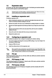
.... The following sub‑sections describe the slots and the expansion cards that you intend to do not need to the card. 3. Align the card connector with it by adjusting the software settings. 1. Failure to use . 4. Assign an IRQ to install expansion cards. Install the software drivers for later use . Remove...
.... The following sub‑sections describe the slots and the expansion cards that you intend to do not need to the card. 3. Align the card connector with it by adjusting the software settings. 1. Failure to use . 4. Assign an IRQ to install expansion cards. Install the software drivers for later use . Remove...

A55M-A User's Manual
Page 34
1.8 1.8.1 1 Connectors Rear panel ports 2 3 45 11 10 9 8 7 6 1. PS/2 Mouse port (green). Video Graphics Adapter (VGA) port. Line In port (light blue). Audio 2, 4, 6, or 8-channel configuration Port ...
1.8 1.8.1 1 Connectors Rear panel ports 2 3 45 11 10 9 8 7 6 1. PS/2 Mouse port (green). Video Graphics Adapter (VGA) port. Line In port (light blue). Audio 2, 4, 6, or 8-channel configuration Port ...

A55M-A User's Manual
Page 35
... 2A (24 W) fan power. • Only the CPU_FAN connector support the ASUS Fan Xpert feature. USB 3.0 ports 11 and 12 (A55M-A/USB3 only). DVI-D port. PS/2 Keyboard port (purple). USB 2.0 ports 11 and 12 (A55M-A only). This port is for USB 2.0/1.1 devices. 8. CPU_FAN CHA_FAN A55M-A/USB3 A55M-A/USB3 CPU fan connector DO NOT forget to connect the fan cables to...
... 2A (24 W) fan power. • Only the CPU_FAN connector support the ASUS Fan Xpert feature. USB 3.0 ports 11 and 12 (A55M-A/USB3 only). DVI-D port. PS/2 Keyboard port (purple). USB 2.0 ports 11 and 12 (A55M-A only). This port is for USB 2.0/1.1 devices. 8. CPU_FAN CHA_FAN A55M-A/USB3 A55M-A/USB3 CPU fan connector DO NOT forget to connect the fan cables to...

A55M-A User's Manual
Page 36
... may become unstable or may not boot up if the power is inadequate. • If you intend to fit these connectors in only one orientation. 2. ATX12V EATXPWR +12V DC +12V DC A55M-A/USB3 GND GND +3 Volts +12 Volts +12 Volts +5V Standby Power OK PIN 1 GND +5 Volts GND +5 Volts GND +3 Volts +3...an ATX power supply. Otherwise, the system will not boot up. • We recommend that the 20-pin power plug can provide at http://support.asus. This PSU type has 24-pin and 4-pin power plugs. • If you use an ATX 12V Specification 2.0‑compliant power supply unit (PSU...
... may become unstable or may not boot up if the power is inadequate. • If you intend to fit these connectors in only one orientation. 2. ATX12V EATXPWR +12V DC +12V DC A55M-A/USB3 GND GND +3 Volts +12 Volts +12 Volts +5V Standby Power OK PIN 1 GND +5 Volts GND +5 Volts GND +3 Volts +3...an ATX power supply. Otherwise, the system will not boot up. • We recommend that the 20-pin power plug can provide at http://support.asus. This PSU type has 24-pin and 4-pin power plugs. • If you use an ATX 12V Specification 2.0‑compliant power supply unit (PSU...
A55M-A User's Manual
Page 37
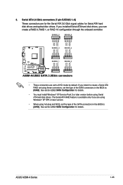
...Gb/s signal cables for Serial ATA hard disk drives and optical disc drives. ASUS A55M-A Series 1-25 3. If you intend to create a Serial ATA RAID set using these connectors, set to AHCI mode by default. SATA3G_5 SATA3G_6 GND RSATA_TXP6 RSATA_TXN6 GND RSATA_RXN6... RSATA_RXP3 RSATA_RXN3 GND RSATA_TXN3 RSATA_TXP3 GND A55M-A/USB3 SATA3G_1 SATA3G_2 GND RSATA_RXP1 RSATA_RXN1 GND RSATA_TXN1 RSATA_TXP1 GND GND RSATA_RXP2 RSATA_RXN2 GND RSATA_TXN2 RSATA_TXP2 GND A55M-A/USB3 SATA 3.0Gb/s connectors • These connectors are set the type of the SATA connectors in the BIOS to [AHCI]....
...Gb/s signal cables for Serial ATA hard disk drives and optical disc drives. ASUS A55M-A Series 1-25 3. If you intend to create a Serial ATA RAID set using these connectors, set to AHCI mode by default. SATA3G_5 SATA3G_6 GND RSATA_TXP6 RSATA_TXN6 GND RSATA_RXN6... RSATA_RXP3 RSATA_RXN3 GND RSATA_TXN3 RSATA_TXP3 GND A55M-A/USB3 SATA3G_1 SATA3G_2 GND RSATA_RXP1 RSATA_RXN1 GND RSATA_TXN1 RSATA_TXP1 GND GND RSATA_RXP2 RSATA_RXN2 GND RSATA_TXN2 RSATA_TXP2 GND A55M-A/USB3 SATA 3.0Gb/s connectors • These connectors are set the type of the SATA connectors in the BIOS to [AHCI]....
A55M-A User's Manual
Page 38
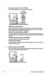
... system beeps and warnings. +5V GND GND Speaker Out A55M-A/USB3 SPEAKER PIN 1 A55M-A/USB3 Speaker Out Connector 1-26 Chapter 1: Product introduction Connect the HDD Activity LED cable to this connector. Ground HWRST# (NC) A55M-A/USB3 PIN 1 +HD_LED RESET A55M-A/USB3 System panel connector • System power LED (2-pin PLED) This 2-pin connector is for the chassis-mounted reset button for the...
... system beeps and warnings. +5V GND GND Speaker Out A55M-A/USB3 SPEAKER PIN 1 A55M-A/USB3 Speaker Out Connector 1-26 Chapter 1: Product introduction Connect the HDD Activity LED cable to this connector. Ground HWRST# (NC) A55M-A/USB3 PIN 1 +HD_LED RESET A55M-A/USB3 System panel connector • System power LED (2-pin PLED) This 2-pin connector is for the chassis-mounted reset button for the...
A55M-A User's Manual
Page 39
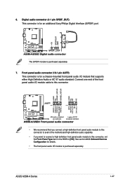
... the Front Panel Type item in the BIOS to this connector. 6. Digital audio connector (4-1 pin SPDIF_OUT) This connector is for an additional Sony/Philips Digital Interface (S/PDIF) port. +5V SPDIFOUT GND A55M-A/USB3 SPDIF_OUT A55M-A/USB3 Digital audio connector The S/PDIF module is purchased separately. ASUS A55M-A Series 1-27 See section 2.5.5 Onboard Devices Configuration for a chassis-mounted front panel audio...
... the Front Panel Type item in the BIOS to this connector. 6. Digital audio connector (4-1 pin SPDIF_OUT) This connector is for an additional Sony/Philips Digital Interface (S/PDIF) port. +5V SPDIFOUT GND A55M-A/USB3 SPDIF_OUT A55M-A/USB3 Digital audio connector The S/PDIF module is purchased separately. ASUS A55M-A Series 1-27 See section 2.5.5 Onboard Devices Configuration for a chassis-mounted front panel audio...

A55M-A User's Manual
Page 40
... USB+5V USB_P6USB_P6+ GND NC USB+5V USB_P4USB_P4+ GND NC A55M-A/USB3 PIN 1 PIN 1 USB+5V USB_P5USB_P5+ GND USB+5V USB_P3USB_P3+ GND A55M-A/USB3 USB2.0 connectors Never connect a 1394 cable to 480Mbps connection speed. These USB connectors comply with USB 2.0 specification that supports up to the USB connectors. Doing so will damage the motherboard! 8. The USB 2.0 module...
... USB+5V USB_P6USB_P6+ GND NC USB+5V USB_P4USB_P4+ GND NC A55M-A/USB3 PIN 1 PIN 1 USB+5V USB_P5USB_P5+ GND USB+5V USB_P3USB_P3+ GND A55M-A/USB3 USB2.0 connectors Never connect a 1394 cable to 480Mbps connection speed. These USB connectors comply with USB 2.0 specification that supports up to the USB connectors. Doing so will damage the motherboard! 8. The USB 2.0 module...
A55M-A User's Manual
Page 62
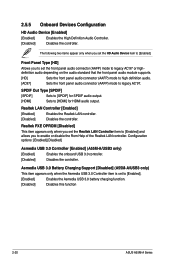
...standard that the front panel audio module supports. [HD] Sets the front panel audio connector (AAFP) mode to high definition audio. [AC97] Sets the front panel audio connector (AAFP) mode to enable or disable the Rom Help of the Realtek LAN controller.... Sets to [Enabled]. [Enabled] Enables the Asmedia USB 3.0 battery charging function. [Disabled] Disables this function 2-20 ASUS A55M-A Series Configuration options: [Enabled] [Disabled] Asmedia USB 3.0 Controller [Enabled] (A55M-A/USB3 only) [Enabled] Enables the onboard USB 3.0 controller. [Disabled] Disables the controller.
...standard that the front panel audio module supports. [HD] Sets the front panel audio connector (AAFP) mode to high definition audio. [AC97] Sets the front panel audio connector (AAFP) mode to enable or disable the Rom Help of the Realtek LAN controller.... Sets to [Enabled]. [Enabled] Enables the Asmedia USB 3.0 battery charging function. [Disabled] Disables this function 2-20 ASUS A55M-A Series Configuration options: [Enabled] [Disabled] Asmedia USB 3.0 Controller [Enabled] (A55M-A/USB3 only) [Enabled] Enables the onboard USB 3.0 controller. [Disabled] Disables the controller.


