

A55BM-K User's Manual
Page 1
A55BM-K Motherboard
A55BM-K Motherboard
A55BM-K User's Manual
Page 3
Contents Safety information...iv About this guide...iv Package contents...vi A55BM-K specifications summary vi Product introduction 1.1 Before you proceed 1-1 1.2 Motherboard overview 1-2 1.3 Accelerated Processing Unit (APU 1-4 1.4 System memory 1-7 1.5 Expansion slots 1-10 1.6 Jumpers...1-11 1.7 Connectors 1-13 1.8 Software support 1-21 BIOS information 2.1 Managing and updating your ... 2-10 2.5 Ai Tweaker menu 2-11 2.6 Advanced menu 2-12 2.7 Monitor menu 2-12 2.8 Boot menu 2-13 2.9 Tools menu 2-14 2.10 Exit menu...2-14 Appendices Notices...A-1 ASUS contact information A-4 iii
Contents Safety information...iv About this guide...iv Package contents...vi A55BM-K specifications summary vi Product introduction 1.1 Before you proceed 1-1 1.2 Motherboard overview 1-2 1.3 Accelerated Processing Unit (APU 1-4 1.4 System memory 1-7 1.5 Expansion slots 1-10 1.6 Jumpers...1-11 1.7 Connectors 1-13 1.8 Software support 1-21 BIOS information 2.1 Managing and updating your ... 2-10 2.5 Ai Tweaker menu 2-11 2.6 Advanced menu 2-12 2.7 Monitor menu 2-12 2.8 Boot menu 2-13 2.9 Tools menu 2-14 2.10 Exit menu...2-14 Appendices Notices...A-1 ASUS contact information A-4 iii

A55BM-K User's Manual
Page 4
...the grounding circuit. • Ensure that your area. If you add a device. • Before connecting or removing signal cables from the motherboard, ensure that all cables are correctly connected and the power cables are not damaged. About this guide is set to the correct voltage in..., ensure that the power cables for the devices are unplugged before using an adapter or extension cord. Operation safety • Before installing the motherboard and adding devices on a stable surface. • If you are using the product, ensure all power cables are unplugged. • Seek...
...the grounding circuit. • Ensure that your area. If you add a device. • Before connecting or removing signal cables from the motherboard, ensure that all cables are correctly connected and the power cables are not damaged. About this guide is set to the correct voltage in..., ensure that the power cables for the devices are unplugged before using an adapter or extension cord. Operation safety • Before installing the motherboard and adding devices on a stable surface. • If you are using the product, ensure all power cables are unplugged. • Seek...

A55BM-K User's Manual
Page 6
...® A55 FCH (Hudson D2) 2 x DDR3 DIMM, max. 32GB, DDR3 2133* / 1866 / 1600 / 1333 MHz, non- Package contents Check your motherboard package for the following items. Motherboard Cables Accessories Application DVD Documentation ASUS A55BM-K motherboard 2 x Serial ATA 3.0 Gb/s cables 1 x I/O Shield Support DVD User Guide If any of 3GB system memory if you install a total memory...
...® A55 FCH (Hudson D2) 2 x DDR3 DIMM, max. 32GB, DDR3 2133* / 1866 / 1600 / 1333 MHz, non- Package contents Check your motherboard package for the following items. Motherboard Cables Accessories Application DVD Documentation ASUS A55BM-K motherboard 2 x Serial ATA 3.0 Gb/s cables 1 x I/O Shield Support DVD User Guide If any of 3GB system memory if you install a total memory...
A55BM-K User's Manual
Page 9
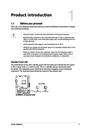
... from the power supply. Failure to do so may cause severe damage to indicate that lights up to the motherboard, peripherals, or components. SB_PWR A55BM-K ON OFF Standby Power Powered Off A55BM-K Onboard LED ASUS A55BM-K 1-1 This is a reminder that the ATX power supply is detached from the wall socket before removing or plugging in...
... from the power supply. Failure to do so may cause severe damage to indicate that lights up to the motherboard, peripherals, or components. SB_PWR A55BM-K ON OFF Standby Power Powered Off A55BM-K Onboard LED ASUS A55BM-K 1-1 This is a reminder that the ATX power supply is detached from the wall socket before removing or plugging in...

A55BM-K User's Manual
Page 10
...the screws! Doing so can cause you physical injury and damage motherboard components. 1.2.1 Placement direction When installing the motherboard, ensure that the motherboard fits into it into the holes indicated by circles to secure the motherboard to the chassis. The edge with external ports goes to ...as indicated in the image below. 1.2.2 Screw holes Place six screws into the chassis in the correct orientation. 1.2 Motherboard overview Before you install the motherboard, study the configuration of your chassis to ensure that you place it . Place this side towards the rear of the...
...the screws! Doing so can cause you physical injury and damage motherboard components. 1.2.1 Placement direction When installing the motherboard, ensure that the motherboard fits into it into the holes indicated by circles to secure the motherboard to the chassis. The edge with external ports goes to ...as indicated in the image below. 1.2.2 Screw holes Place six screws into the chassis in the correct orientation. 1.2 Motherboard overview Before you install the motherboard, study the configuration of your chassis to ensure that you place it . Place this side towards the rear of the...

A55BM-K User's Manual
Page 11
...connector (10-1 pin AAFP) SATA3G_4 2 6 7 8 Page 1-13 1-16 1-4 1-15 1-7 1-18 1-17 1-18 1-20 1-11 1-12 1-17 1-20 1-1 1-19 ASUS A55BM-K 1-3 1.2.3 Motherboard layout 1 2 3 4 5 18.3cm(7.2in) KBMS ATX12V DIGI +VRM CPU_FAN CHA_FAN DDR3 DIMM_A1 (64bit, 240-pin module) DDR3 DIMM_B1 (64bit, 240-pin module) SOCKET... FM2+ DVI_VGA 22.6cm(8.9in) USB1112 EATXPWR LAN_USB12 AUDIO RTL 8111G KB_USBWB ASM 1042 A55BM-K PCIEX16 Super I/O SB_PWR PCIEX1_1 BATTERY ALC 887 AAFP PCI1 COM SPDIF_OUT USBPWF CLRTC USB56 AMD® A55 SPEAKER USB34 F_PANEL...
...connector (10-1 pin AAFP) SATA3G_4 2 6 7 8 Page 1-13 1-16 1-4 1-15 1-7 1-18 1-17 1-18 1-20 1-11 1-12 1-17 1-20 1-1 1-19 ASUS A55BM-K 1-3 1.2.3 Motherboard layout 1 2 3 4 5 18.3cm(7.2in) KBMS ATX12V DIGI +VRM CPU_FAN CHA_FAN DDR3 DIMM_A1 (64bit, 240-pin module) DDR3 DIMM_B1 (64bit, 240-pin module) SOCKET... FM2+ DVI_VGA 22.6cm(8.9in) USB1112 EATXPWR LAN_USB12 AUDIO RTL 8111G KB_USBWB ASM 1042 A55BM-K PCIEX16 Super I/O SB_PWR PCIEX1_1 BATTERY ALC 887 AAFP PCI1 COM SPDIF_OUT USBPWF CLRTC USB56 AMD® A55 SPEAKER USB34 F_PANEL...

A55BM-K User's Manual
Page 12
1.3 Accelerated Processing Unit (APU) This motherboard comes with an FM2+ socket designed for the FM2+ socket. DO NOT force the APU into the socket to prevent bending the pins and damaging the APU! 1.3.1 Installing the APU 1 2 1-4 Chapter 1: Product introduction A55BM-K A55BM-K CPU socket FM2+ Ensure that you use an APU designed for AMD® A-series accelerated processors with AMD® Radeon™ HD 7000/8000 series graphics. The APU fits in only one correct orientation.
1.3 Accelerated Processing Unit (APU) This motherboard comes with an FM2+ socket designed for the FM2+ socket. DO NOT force the APU into the socket to prevent bending the pins and damaging the APU! 1.3.1 Installing the APU 1 2 1-4 Chapter 1: Product introduction A55BM-K A55BM-K CPU socket FM2+ Ensure that you use an APU designed for AMD® A-series accelerated processors with AMD® Radeon™ HD 7000/8000 series graphics. The APU fits in only one correct orientation.
A55BM-K User's Manual
Page 15
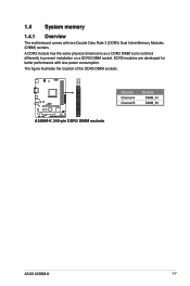
The figure illustrates the location of the DDR3 DIMM sockets: DIMM_A1 DIMM_B1 A55BM-K A55BM-K 240-pin DDR3 DIMM sockets Channel Channel A Channel B Sockets DIMM_A1 DIMM_B1 ASUS A55BM-K 1-7 A DDR3 module has the same physical dimensions as a DDR2 DIMM but is notched differently to prevent installation on a DDR2 DIMM socket. DDR3 modules are developed for better performance with two Double Data Rate 3 (DDR3) Dual Inline Memory Modules (DIMM) sockets. 1.4 System memory 1.4.1 Overview The motherboard comes with less power consumption.
The figure illustrates the location of the DDR3 DIMM sockets: DIMM_A1 DIMM_B1 A55BM-K A55BM-K 240-pin DDR3 DIMM sockets Channel Channel A Channel B Sockets DIMM_A1 DIMM_B1 ASUS A55BM-K 1-7 A DDR3 module has the same physical dimensions as a DDR2 DIMM but is notched differently to prevent installation on a DDR2 DIMM socket. DDR3 modules are developed for better performance with two Double Data Rate 3 (DDR3) Dual Inline Memory Modules (DIMM) sockets. 1.4 System memory 1.4.1 Overview The motherboard comes with less power consumption.
A55BM-K User's Manual
Page 16
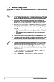
...memory cooling system to support a full memory load (2 DIMMs) or overclocking condition. • Refer to install 4GB or more memory on the motherboard. • This motherboard does not support DIMMs made up of 512Mb (64MB) chips or less. • The maximum 32GB memory capacity can be supported with 16GB or... above DIMMs. ASUS will update the memory QVL once the DIMMs are using a 32-bit Windows® OS. - The system maps the total size...
...memory cooling system to support a full memory load (2 DIMMs) or overclocking condition. • Refer to install 4GB or more memory on the motherboard. • This motherboard does not support DIMMs made up of 512Mb (64MB) chips or less. • The maximum 32GB memory capacity can be supported with 16GB or... above DIMMs. ASUS will update the memory QVL once the DIMMs are using a 32-bit Windows® OS. - The system maps the total size...
A55BM-K User's Manual
Page 18
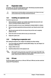
...PCI slot The PCI slot supports cards such as a LAN card, SCSI card, USB card, and other cards that you physical injury and damage motherboard components. 1.5.1 Installing an expansion card To install an expansion card: 1. The following sub‑sections describe the slots and the expansion cards that...with the screw you removed earlier. 6. Unplug the power cord before adding or removing expansion cards. Remove the system unit cover (if your motherboard is completely seated on BIOS setup. 2. Secure the card to the card. 3. When using PCI cards on the system and change the ...
...PCI slot The PCI slot supports cards such as a LAN card, SCSI card, USB card, and other cards that you physical injury and damage motherboard components. 1.5.1 Installing an expansion card To install an expansion card: 1. The following sub‑sections describe the slots and the expansion cards that...with the screw you removed earlier. 6. Unplug the power cord before adding or removing expansion cards. Remove the system unit cover (if your motherboard is completely seated on BIOS setup. 2. Secure the card to the card. 3. When using PCI cards on the system and change the ...

A55BM-K User's Manual
Page 19
PCIEx1_1 shared - - - - - - - shared - - - A55BM-K CLRTC 12 23 Normal (Default) A55BM-K Clear RTC RAM Clear RTC ASUS A55BM-K 1-11 SATA controller - - - On Chip USB EHCI 1/2/3 - shared - - - - - 1.6 Jumpers Clear ...- - - Realtek LAN controller - - shared - - - - The onboard button cell battery powers the RAM data in CMOS. shared - - - - - 1.5.4 PCI Express x1 slot This motherboard supports PCI Express 2.0 x1 network cards, SCSI cards, and other cards that comply with the PCI Express specifications. 1.5.5 PCI Express x16 slot This...
PCIEx1_1 shared - - - - - - - shared - - - A55BM-K CLRTC 12 23 Normal (Default) A55BM-K Clear RTC RAM Clear RTC ASUS A55BM-K 1-11 SATA controller - - - On Chip USB EHCI 1/2/3 - shared - - - - - 1.6 Jumpers Clear ...- - - Realtek LAN controller - - shared - - - - The onboard button cell battery powers the RAM data in CMOS. shared - - - - - 1.5.4 PCI Express x1 slot This motherboard supports PCI Express 2.0 x1 network cards, SCSI cards, and other cards that comply with the PCI Express specifications. 1.5.5 PCI Express x16 slot This...
A55BM-K User's Manual
Page 23
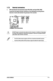
...not jumpers! DO NOT place jumper caps on the motherboard, ensuring that the black wire of each cable matches the ground pin of maximum 2A (24 W) fan power. • The CPU_FAN and CHA_FAN connectors support the ASUS Fan Xpert feature. CPU_FAN CHA_FAN A55BM-K A55BM-K Fan connectors DO NOT forget to connect the fan... a CPU fan of the connector. CPU and chassis fan connectors (4-pin CPU_FAN, and 4-pin CHA_FAN) Connect the fan cables to the fan connectors. ASUS A55BM-K 1-15 CPU FAN PWM CPU FAN IN CPU FAN PWR GND CHA FAN PWM CHA FAN IN CHA FAN PWR GND 1.7.2 Internal connectors 1.
...not jumpers! DO NOT place jumper caps on the motherboard, ensuring that the black wire of each cable matches the ground pin of maximum 2A (24 W) fan power. • The CPU_FAN and CHA_FAN connectors support the ASUS Fan Xpert feature. CPU_FAN CHA_FAN A55BM-K A55BM-K Fan connectors DO NOT forget to connect the fan... a CPU fan of the connector. CPU and chassis fan connectors (4-pin CPU_FAN, and 4-pin CHA_FAN) Connect the fan cables to the fan connectors. ASUS A55BM-K 1-15 CPU FAN PWM CPU FAN IN CPU FAN PWR GND CHA FAN PWM CHA FAN IN CHA FAN PWR GND 1.7.2 Internal connectors 1.
A55BM-K User's Manual
Page 27
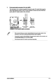
...`97 audio standard. ASUS A55BM-K 1-19 Connect one end of the front panel audio I/O module cable to [HD]. • The front panel audio I/O module is for a chassis-mounted front panel audio I/O module that you connect a high-definition front panel audio module to this connector to avail of the motherboard high-definition audio capability...
...`97 audio standard. ASUS A55BM-K 1-19 Connect one end of the front panel audio I/O module cable to [HD]. • The front panel audio I/O module is for a chassis-mounted front panel audio I/O module that you connect a high-definition front panel audio module to this connector to avail of the motherboard high-definition audio capability...
A55BM-K User's Manual
Page 28
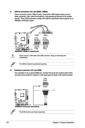
Doing so will damage the motherboard! Connect the USB module cable to any of these connectors, then install the module to a slot opening at the back of the system chassis. USB56 USB34 USB+5V USB_P5USB_P5+ GND NC USB+5V USB_P3USB_P3+ GND NC A55BM-K PIN 1 PIN 1 USB+5V USB_P6USB_P6+ ...GND USB+5V USB_P4USB_P4+ GND A55BM-K USB2.0 connectors Never connect a 1394 cable to 480Mbps connection speed. Serial port connector (10-1 pin COM)...
Doing so will damage the motherboard! Connect the USB module cable to any of these connectors, then install the module to a slot opening at the back of the system chassis. USB56 USB34 USB+5V USB_P5USB_P5+ GND NC USB+5V USB_P3USB_P3+ GND NC A55BM-K PIN 1 PIN 1 USB+5V USB_P6USB_P6+ ...GND USB+5V USB_P4USB_P4+ GND A55BM-K USB2.0 connectors Never connect a 1394 cable to 480Mbps connection speed. Serial port connector (10-1 pin COM)...
A55BM-K User's Manual
Page 29
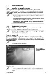
... maximize the features of the Support DVD are subject to avail all motherboard features. If Autorun is NOT enabled in your computer, browse the contents of ASUS motherboard. The following screen is for updates. Visit the ASUS website at any time without notice. ASUS A55BM-K 1-21 Double-click the ASSETUP.EXE to display their respective menus...
... maximize the features of the Support DVD are subject to avail all motherboard features. If Autorun is NOT enabled in your computer, browse the contents of ASUS motherboard. The following screen is for updates. Visit the ASUS website at any time without notice. ASUS A55BM-K 1-21 Double-click the ASSETUP.EXE to display their respective menus...

A55BM-K User's Manual
Page 31
... utlity, you need to update the BIOS EZ Update requires an Internet connection either through a network or an ISP (Internet Service Provider). ASUS A55BM-K 2-1 Click to automatically update your motherboard's driver, software and firmware Click to find and select the BIOS from file Click to select a boot logo Click to restore the BIOS...
... utlity, you need to update the BIOS EZ Update requires an Internet connection either through a network or an ISP (Internet Service Provider). ASUS A55BM-K 2-1 Click to automatically update your motherboard's driver, software and firmware Click to find and select the BIOS from file Click to select a boot logo Click to restore the BIOS...

A55BM-K User's Manual
Page 32
...; Before using the motherboard support DVD or a USB flash drive that contains the latest BIOS, and then press . 5. Press the Up/Down arrow keys to the Drive field. 4. You can restore a corrupted BIOS file using this utility, download the latest BIOS file from the ASUS website at www.asus.com. Press to switch...
...; Before using the motherboard support DVD or a USB flash drive that contains the latest BIOS, and then press . 5. Press the Up/Down arrow keys to the Drive field. 4. You can restore a corrupted BIOS file using this utility, download the latest BIOS file from the ASUS website at www.asus.com. Press to switch...

A55BM-K User's Manual
Page 33
... and single partition. 2. Download the latest BIOS file and BIOS Updater from the ASUS website at http://support.asus.com and save the BIOS file and BIOS Updater to the USB port. 3. ASUS A55BM-K 2-3 Prepare the motherboard support DVD and a USB flash drive in NTFS format. 3. When found, the... utility reads the BIOS file and enters ASUS EZ Flash 2 utility automatically. 4. NTFS is not supported under DOS environment....
... and single partition. 2. Download the latest BIOS file and BIOS Updater from the ASUS website at http://support.asus.com and save the BIOS file and BIOS Updater to the USB port. 3. ASUS A55BM-K 2-3 Prepare the motherboard support DVD and a USB flash drive in NTFS format. 3. When found, the... utility reads the BIOS file and enters ASUS EZ Flash 2 utility automatically. 4. NTFS is not supported under DOS environment....

A55BM-K User's Manual
Page 36
... at www.asus.com to download the latest BIOS file for this section are for details. • If the system fails to boot after changing any BIOS setting, try to clear the CMOS and reset the motherboard to the default value. The EZ Mode provides you an overview of the basic system.... Using the power button, reset button, or the ++ keys to force reset from the Exit/Advanced Mode button in this motherboard. • Ensure that a USB mouse is connected to your motherboard if you want to use the mouse to control the BIOS setup program. • If the system becomes unstable after changing...
... at www.asus.com to download the latest BIOS file for this section are for details. • If the system fails to boot after changing any BIOS setting, try to clear the CMOS and reset the motherboard to the default value. The EZ Mode provides you an overview of the basic system.... Using the power button, reset button, or the ++ keys to force reset from the Exit/Advanced Mode button in this motherboard. • Ensure that a USB mouse is connected to your motherboard if you want to use the mouse to control the BIOS setup program. • If the system becomes unstable after changing...


