

A55BM-K User's Manual
Page 1
A55BM-K Motherboard
A55BM-K Motherboard
A55BM-K User's Manual
Page 3
Contents Safety information...iv About this guide...iv Package contents...vi A55BM-K specifications summary vi Product introduction 1.1 Before you proceed 1-1 1.2 Motherboard overview 1-2 1.3 Accelerated Processing Unit (APU 1-4 1.4 System memory 1-7 1.5 Expansion slots 1-10 1.6 Jumpers...1-11 1.7 Connectors 1-13 1.8 Software support 1-21 BIOS information 2.1 Managing and updating your ... 2-10 2.5 Ai Tweaker menu 2-11 2.6 Advanced menu 2-12 2.7 Monitor menu 2-12 2.8 Boot menu 2-13 2.9 Tools menu 2-14 2.10 Exit menu...2-14 Appendices Notices...A-1 ASUS contact information A-4 iii
Contents Safety information...iv About this guide...iv Package contents...vi A55BM-K specifications summary vi Product introduction 1.1 Before you proceed 1-1 1.2 Motherboard overview 1-2 1.3 Accelerated Processing Unit (APU 1-4 1.4 System memory 1-7 1.5 Expansion slots 1-10 1.6 Jumpers...1-11 1.7 Connectors 1-13 1.8 Software support 1-21 BIOS information 2.1 Managing and updating your ... 2-10 2.5 Ai Tweaker menu 2-11 2.6 Advanced menu 2-12 2.7 Monitor menu 2-12 2.8 Boot menu 2-13 2.9 Tools menu 2-14 2.10 Exit menu...2-14 Appendices Notices...A-1 ASUS contact information A-4 iii

A55BM-K User's Manual
Page 4
... outlet before the signal cables are also provided. If you add a device. • Before connecting or removing signal cables from the motherboard, ensure that the power cables for the devices are unplugged before relocating the system. • When adding or removing devices to change ...system settings through the BIOS Setup menus. Detailed descriptions of the motherboard and the new technology it by yourself. Contact a qualified service technician or your retailer. How this guide This user guide contains the...
... outlet before the signal cables are also provided. If you add a device. • Before connecting or removing signal cables from the motherboard, ensure that the power cables for the devices are unplugged before relocating the system. • When adding or removing devices to change ...system settings through the BIOS Setup menus. Detailed descriptions of the motherboard and the new technology it by yourself. Contact a qualified service technician or your retailer. How this guide This user guide contains the...

A55BM-K User's Manual
Page 6
...; Radeon™ HD 7000 / 8000 Series Graphics in the market. • Hyper DIMM support is damaged or missing, contact your motherboard package for the following items. Motherboard Cables Accessories Application DVD Documentation ASUS A55BM-K motherboard 2 x Serial ATA 3.0 Gb/s cables 1 x I/O Shield Support DVD User Guide If any of 2G Supports AMD® Dual Graphics technology •...
...; Radeon™ HD 7000 / 8000 Series Graphics in the market. • Hyper DIMM support is damaged or missing, contact your motherboard package for the following items. Motherboard Cables Accessories Application DVD Documentation ASUS A55BM-K motherboard 2 x Serial ATA 3.0 Gb/s cables 1 x I/O Shield Support DVD User Guide If any of 2G Supports AMD® Dual Graphics technology •...
A55BM-K User's Manual
Page 9
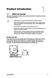
... 1 1.1 Before you proceed Take note of the onboard LED. Standby Power LED The motherboard comes with the component. • Before you uninstall any motherboard component. This is a reminder that you should shut down the system and unplug the power...motherboard, peripherals, or components. The illustration below shows the location of the following precautions before you install motherboard components or change any motherboard settings. • Unplug the power cord from the power supply. SB_PWR A55BM-K ON OFF Standby Power Powered Off A55BM-K Onboard LED ASUS A55BM...
... 1 1.1 Before you proceed Take note of the onboard LED. Standby Power LED The motherboard comes with the component. • Before you uninstall any motherboard component. This is a reminder that you should shut down the system and unplug the power...motherboard, peripherals, or components. The illustration below shows the location of the following precautions before you install motherboard components or change any motherboard settings. • Unplug the power cord from the power supply. SB_PWR A55BM-K ON OFF Standby Power Powered Off A55BM-K Onboard LED ASUS A55BM...

A55BM-K User's Manual
Page 10
... place it into the chassis in the image below. 1.2.2 Screw holes Place six screws into it. 1.2 Motherboard overview Before you install the motherboard, study the configuration of the chassis A55BM-K 1-2 Chapter 1: Product introduction Failure to do so can damage the motherboard. Place this side towards the rear of your chassis to ensure that the...
... place it into the chassis in the image below. 1.2.2 Screw holes Place six screws into it. 1.2 Motherboard overview Before you install the motherboard, study the configuration of the chassis A55BM-K 1-2 Chapter 1: Product introduction Failure to do so can damage the motherboard. Place this side towards the rear of your chassis to ensure that the...

A55BM-K User's Manual
Page 11
...pin USB34, USB56) 10. Standby power LED (SB_PWR) 15. USB device wake-up (3-pin KB_USBPWB) 2. Clear RTC RAM (3-pin CLRTC) 11. 1.2.3 Motherboard layout 1 2 3 4 5 18.3cm(7.2in) KBMS ATX12V DIGI +VRM CPU_FAN CHA_FAN DDR3 DIMM_A1 (64bit, 240-pin module) DDR3 DIMM_B1 (64bit, 240-... (10-1 pin AAFP) SATA3G_4 2 6 7 8 Page 1-13 1-16 1-4 1-15 1-7 1-18 1-17 1-18 1-20 1-11 1-12 1-17 1-20 1-1 1-19 ASUS A55BM-K 1-3 ATX power connectors (24-pin EATXPWR, 4-pin ATX12V) 3. DDR3 DIMM slots 6. SATA 3.0Gb/s connectors (7-pin SATA3G_1~4) 8. Keyboard and USB device wake up (3-pin...
...pin USB34, USB56) 10. Standby power LED (SB_PWR) 15. USB device wake-up (3-pin KB_USBPWB) 2. Clear RTC RAM (3-pin CLRTC) 11. 1.2.3 Motherboard layout 1 2 3 4 5 18.3cm(7.2in) KBMS ATX12V DIGI +VRM CPU_FAN CHA_FAN DDR3 DIMM_A1 (64bit, 240-pin module) DDR3 DIMM_B1 (64bit, 240-... (10-1 pin AAFP) SATA3G_4 2 6 7 8 Page 1-13 1-16 1-4 1-15 1-7 1-18 1-17 1-18 1-20 1-11 1-12 1-17 1-20 1-1 1-19 ASUS A55BM-K 1-3 ATX power connectors (24-pin EATXPWR, 4-pin ATX12V) 3. DDR3 DIMM slots 6. SATA 3.0Gb/s connectors (7-pin SATA3G_1~4) 8. Keyboard and USB device wake up (3-pin...

A55BM-K User's Manual
Page 12
The APU fits in only one correct orientation. DO NOT force the APU into the socket to prevent bending the pins and damaging the APU! 1.3.1 Installing the APU 1 2 1-4 Chapter 1: Product introduction 1.3 Accelerated Processing Unit (APU) This motherboard comes with AMD® Radeon™ HD 7000/8000 series graphics. A55BM-K A55BM-K CPU socket FM2+ Ensure that you use an APU designed for AMD® A-series accelerated processors with an FM2+ socket designed for the FM2+ socket.
The APU fits in only one correct orientation. DO NOT force the APU into the socket to prevent bending the pins and damaging the APU! 1.3.1 Installing the APU 1 2 1-4 Chapter 1: Product introduction 1.3 Accelerated Processing Unit (APU) This motherboard comes with AMD® Radeon™ HD 7000/8000 series graphics. A55BM-K A55BM-K CPU socket FM2+ Ensure that you use an APU designed for AMD® A-series accelerated processors with an FM2+ socket designed for the FM2+ socket.
A55BM-K User's Manual
Page 15
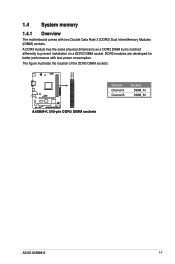
The figure illustrates the location of the DDR3 DIMM sockets: DIMM_A1 DIMM_B1 A55BM-K A55BM-K 240-pin DDR3 DIMM sockets Channel Channel A Channel B Sockets DIMM_A1 DIMM_B1 ASUS A55BM-K 1-7 DDR3 modules are developed for better performance with two Double Data Rate 3 (DDR3) Dual Inline Memory Modules (DIMM) sockets. A DDR3 module has the same physical dimensions as a DDR2 DIMM but is notched differently to prevent installation on a DDR2 DIMM socket. 1.4 System memory 1.4.1 Overview The motherboard comes with less power consumption.
The figure illustrates the location of the DDR3 DIMM sockets: DIMM_A1 DIMM_B1 A55BM-K A55BM-K 240-pin DDR3 DIMM sockets Channel Channel A Channel B Sockets DIMM_A1 DIMM_B1 ASUS A55BM-K 1-7 DDR3 modules are developed for better performance with two Double Data Rate 3 (DDR3) Dual Inline Memory Modules (DIMM) sockets. A DDR3 module has the same physical dimensions as a DDR2 DIMM but is notched differently to prevent installation on a DDR2 DIMM socket. 1.4 System memory 1.4.1 Overview The motherboard comes with less power consumption.
A55BM-K User's Manual
Page 16
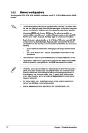
...Product introduction The system maps the total size of the following: - Any excess memory from the higher-sized channel is dependent on the motherboard. • This motherboard does not support DIMMs made up of the same version or date code (D/C) from a memory module. Use a 64-bit Windows®... 32GB memory capacity can be supported with 16GB or above DIMMs. ASUS will update the memory QVL once the DIMMs are using a 32-bit Windows® OS. - For effective use a more memory on the motherboard, the actual usable memory for the dual-channel configuration. To operate...
...Product introduction The system maps the total size of the following: - Any excess memory from the higher-sized channel is dependent on the motherboard. • This motherboard does not support DIMMs made up of the same version or date code (D/C) from a memory module. Use a 64-bit Windows®... 32GB memory capacity can be supported with 16GB or above DIMMs. ASUS will update the memory QVL once the DIMMs are using a 32-bit Windows® OS. - For effective use a more memory on the motherboard, the actual usable memory for the dual-channel configuration. To operate...
A55BM-K User's Manual
Page 18
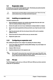
Remove the system unit cover (if your motherboard is completely seated on shared slots, ensure that the drivers support "Share IRQ" or that you intend to install expansion cards. Assign an IRQ to ...the chassis with PCI specifications. 1-10 Chapter 1: Product introduction 1.5 Expansion slots In the future, you may cause you physical injury and damage motherboard components. 1.5.1 Installing an expansion card To install an expansion card: 1. Failure to do not need to use . 4. Align the card connector with it by adjusting...
Remove the system unit cover (if your motherboard is completely seated on shared slots, ensure that the drivers support "Share IRQ" or that you intend to install expansion cards. Assign an IRQ to ...the chassis with PCI specifications. 1-10 Chapter 1: Product introduction 1.5 Expansion slots In the future, you may cause you physical injury and damage motherboard components. 1.5.1 Installing an expansion card To install an expansion card: 1. Failure to do not need to use . 4. Align the card connector with it by adjusting...

A55BM-K User's Manual
Page 19
... system setup information such as system passwords. shared - - - - On Chip USB OHCI 1/2/3/4 - - PCIEx1_1 shared - - - - - - - shared - - - IRQ assignments for this motherboard A B C D E F G H PCIEx16_1 - - A55BM-K CLRTC 12 23 Normal (Default) A55BM-K Clear RTC RAM Clear RTC ASUS A55BM-K 1-11 You can clear the CMOS memory of date, time, and system setup parameters by erasing the CMOS RTC RAM...
... system setup information such as system passwords. shared - - - - On Chip USB OHCI 1/2/3/4 - - PCIEx1_1 shared - - - - - - - shared - - - IRQ assignments for this motherboard A B C D E F G H PCIEx16_1 - - A55BM-K CLRTC 12 23 Normal (Default) A55BM-K Clear RTC RAM Clear RTC ASUS A55BM-K 1-11 You can clear the CMOS memory of date, time, and system setup parameters by erasing the CMOS RTC RAM...
A55BM-K User's Manual
Page 23
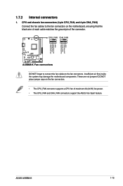
... 4-pin CHA_FAN) Connect the fan cables to the fan connectors. Insufficient air flow inside the system may damage the motherboard components. ASUS A55BM-K 1-15 These are not jumpers! DO NOT place jumper caps on the motherboard, ensuring that the black wire of each cable matches the ground pin of maximum 2A (24 W) fan power...
... 4-pin CHA_FAN) Connect the fan cables to the fan connectors. Insufficient air flow inside the system may damage the motherboard components. ASUS A55BM-K 1-15 These are not jumpers! DO NOT place jumper caps on the motherboard, ensuring that the black wire of each cable matches the ground pin of maximum 2A (24 W) fan power...
A55BM-K User's Manual
Page 27
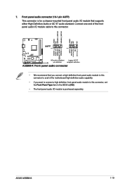
7. Connect one end of the motherboard high-definition audio capability. • If you want to connect a high definition front panel audio module to this connector, set the Front Panel Type item ... MICPWR Line out_R NC Line out_L PORT1 L PORT1 R PORT2 R SENSE_SEND PORT2 L A55BM-K HD-audio-compliant Legacy AC'97 pin definition compliant definition A55BM-K Front panel audio connector • We recommend that supports either High Definition Audio or AC`97 audio standard. ASUS A55BM-K 1-19 Front panel audio connector (10-1 pin AAFP) This connector is...
7. Connect one end of the motherboard high-definition audio capability. • If you want to connect a high definition front panel audio module to this connector, set the Front Panel Type item ... MICPWR Line out_R NC Line out_L PORT1 L PORT1 R PORT2 R SENSE_SEND PORT2 L A55BM-K HD-audio-compliant Legacy AC'97 pin definition compliant definition A55BM-K Front panel audio connector • We recommend that supports either High Definition Audio or AC`97 audio standard. ASUS A55BM-K 1-19 Front panel audio connector (10-1 pin AAFP) This connector is...
A55BM-K User's Manual
Page 28
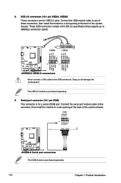
... back of the system chassis. USB56 USB34 USB+5V USB_P5USB_P5+ GND NC USB+5V USB_P3USB_P3+ GND NC A55BM-K PIN 1 PIN 1 USB+5V USB_P6USB_P6+ GND USB+5V USB_P4USB_P4+ GND A55BM-K USB2.0 connectors Never connect a 1394 cable to 480Mbps connection speed. These USB connectors comply with USB... install the module to a slot opening at the back of the system chassis. Doing so will damage the motherboard! COM RXD DTR DSR CTS PIN 1 DCD TXD GND RTS RI A55BM-K A55BM-K Serial port connectors The COM module is purchased separately. 9. 8. The USB 2.0 module is purchased separately....
... back of the system chassis. USB56 USB34 USB+5V USB_P5USB_P5+ GND NC USB+5V USB_P3USB_P3+ GND NC A55BM-K PIN 1 PIN 1 USB+5V USB_P6USB_P6+ GND USB+5V USB_P4USB_P4+ GND A55BM-K USB2.0 connectors Never connect a 1394 cable to 480Mbps connection speed. These USB connectors comply with USB... install the module to a slot opening at the back of the system chassis. Doing so will damage the motherboard! COM RXD DTR DSR CTS PIN 1 DCD TXD GND RTS RI A55BM-K A55BM-K Serial port connectors The COM module is purchased separately. 9. 8. The USB 2.0 module is purchased separately....
A55BM-K User's Manual
Page 29
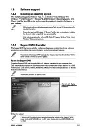
... maximize the features of your computer, browse the contents of ASUS motherboard. To run the DVD. Always install the latest OS version and corresponding updates to change at www.asus.com for reference only. ASUS A55BM-K 1-21 The following screen is enabled in your hardware. • Motherboard settings and hardware options vary. If Autorun is for...
... maximize the features of your computer, browse the contents of ASUS motherboard. To run the DVD. Always install the latest OS version and corresponding updates to change at www.asus.com for reference only. ASUS A55BM-K 1-21 The following screen is enabled in your hardware. • Motherboard settings and hardware options vary. If Autorun is for...

A55BM-K User's Manual
Page 31
Copy the original motherboard BIOS using the ASUS Update utility. 2.1.1 EZ Update EZ Update is a utility that ... saved BIOS and select a boot logo when the system goes into POST. Click to automatically update your motherboard's driver, software and firmware Click to find and select the BIOS from file Click to select a boot... original motherboard BIOS file to a USB flash disk in the future. To launch EZ Update, click EZ Update on the AI Suite 3 main menu bar. BIOS information 2.1 Managing and updating your motherboard's softwares, drivers and the BIOS version easily. ASUS A55BM-K ...
Copy the original motherboard BIOS using the ASUS Update utility. 2.1.1 EZ Update EZ Update is a utility that ... saved BIOS and select a boot logo when the system goes into POST. Click to automatically update your motherboard's driver, software and firmware Click to find and select the BIOS from file Click to select a boot... original motherboard BIOS file to a USB flash disk in the future. To launch EZ Update, click EZ Update on the AI Suite 3 main menu bar. BIOS information 2.1 Managing and updating your motherboard's softwares, drivers and the BIOS version easily. ASUS A55BM-K ...

A55BM-K User's Manual
Page 32
... using an OS‑based utility. You can restore a corrupted BIOS file using the motherboard support DVD or a USB flash drive that contains the latest BIOS, and then press . 5. 2.1.2 ASUS EZ Flash 2 The ASUS EZ Flash 2 feature allows you start using this utility, rename the BIOS file in ... the updated BIOS file. • Before using this utility, download the latest BIOS file from the ASUS website at www.asus.com. Download the latest BIOS file from the ASUS website at www.asus.com. 2-2 Chapter 2: Getting started Enter the Advanced Mode of the BIOS setup program. Press to ...
... using an OS‑based utility. You can restore a corrupted BIOS file using the motherboard support DVD or a USB flash drive that contains the latest BIOS, and then press . 5. 2.1.2 ASUS EZ Flash 2 The ASUS EZ Flash 2 feature allows you start using this utility, rename the BIOS file in ... the updated BIOS file. • Before using this utility, download the latest BIOS file from the ASUS website at www.asus.com. Download the latest BIOS file from the ASUS website at www.asus.com. 2-2 Chapter 2: Getting started Enter the Advanced Mode of the BIOS setup program. Press to ...

A55BM-K User's Manual
Page 33
... at http://support.asus.com and save the BIOS file and BIOS Updater to load default BIOS values. Do not save them on the system. 2. Turn on the USB flash drive. Prepare the motherboard support DVD and a USB flash drive in NTFS format. 3. NTFS is not supported under DOS environment.... during the updating process. Turn off the computer and disconnect all SATA hard disk drives (optional). Doing so can cause system boot failure! 2.1.4 ASUS BIOS Updater The ASUS BIOS Updater allows you can use as shown. ASUS A55BM-K 2-3 Recovering the BIOS To recover the BIOS: 1.
... at http://support.asus.com and save the BIOS file and BIOS Updater to load default BIOS values. Do not save them on the system. 2. Turn on the USB flash drive. Prepare the motherboard support DVD and a USB flash drive in NTFS format. 3. NTFS is not supported under DOS environment.... during the updating process. Turn off the computer and disconnect all SATA hard disk drives (optional). Doing so can cause system boot failure! 2.1.4 ASUS BIOS Updater The ASUS BIOS Updater allows you can use as shown. ASUS A55BM-K 2-3 Recovering the BIOS To recover the BIOS: 1.

A55BM-K User's Manual
Page 36
...erase the RTC RAM. Using the power button, reset button, or the ++ keys to force reset from a running operating system can cause damage to your motherboard if you want to use the mouse to control the BIOS setup program. • If the system becomes unstable after changing any BIOS setting, load... at www.asus.com to your data or system. The EZ Mode provides you an overview of the basic system information, and allows you enter the BIOS setup program. The default screen for this motherboard. • Ensure that a USB mouse is connected to download the latest BIOS file for entering the ...
...erase the RTC RAM. Using the power button, reset button, or the ++ keys to force reset from a running operating system can cause damage to your motherboard if you want to use the mouse to control the BIOS setup program. • If the system becomes unstable after changing any BIOS setting, load... at www.asus.com to your data or system. The EZ Mode provides you an overview of the basic system information, and allows you enter the BIOS setup program. The default screen for this motherboard. • Ensure that a USB mouse is connected to download the latest BIOS file for entering the ...


