

X203W LCD Monitor User's Guide
Page 14
... standard. The DDC (Display Data Channel) is a communication protocol through which the monitor automatically informs the host system about its capabilities, for example, supported resolutions and corresponding timing. The recovery time from the display controller, as indicated by the control signal from Active OFF state back to Plug and Play... with your system if your installation easier, the monitor is activated. X203W Power saving The monitor will be driven into Power Saving" mode by the amber-color power LED.
... standard. The DDC (Display Data Channel) is a communication protocol through which the monitor automatically informs the host system about its capabilities, for example, supported resolutions and corresponding timing. The recovery time from the display controller, as indicated by the control signal from Active OFF state back to Plug and Play... with your system if your installation easier, the monitor is activated. X203W Power saving The monitor will be driven into Power Saving" mode by the amber-color power LED.
X203W LCD Monitor User's Guide
Page 17
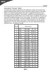
... 4 VESA 5 VESA 6 7 VESA 8 VESA 9 VESA 10 VESA 11 MAC 12 VESA 13 VESA 14 VESA 15 VESA 16 VESA 17 VESA 18 VESA 19 VESA Resolution 720 x 400 70 Hz 640 x 480 59.94 Hz 640 x 480 66.66 Hz 640 x 480 72 Hz 640 x 480 75 Hz 648 x 500 57... x 768 75 Hz 1152 x 864 75 Hz 1280 x 960 60 Hz 1280 x 1024 60 Hz 1280 x 1024 75 Hz 1680 x 1050 60 Hz EN-11 X203W Standard Timing Table To reduce the need for adjustment for vertical frequency or the sync signal polarities are most commonly used as a user mode is...
... 4 VESA 5 VESA 6 7 VESA 8 VESA 9 VESA 10 VESA 11 MAC 12 VESA 13 VESA 14 VESA 15 VESA 16 VESA 17 VESA 18 VESA 19 VESA Resolution 720 x 400 70 Hz 640 x 480 59.94 Hz 640 x 480 66.66 Hz 640 x 480 72 Hz 640 x 480 75 Hz 648 x 500 57... x 768 75 Hz 1152 x 864 75 Hz 1280 x 960 60 Hz 1280 x 1024 60 Hz 1280 x 1024 75 Hz 1680 x 1050 60 Hz EN-11 X203W Standard Timing Table To reduce the need for adjustment for vertical frequency or the sync signal polarities are most commonly used as a user mode is...

X203W LCD Monitor User's Guide
Page 23
... (D-Sub) N/A Digital (only DualInputModel) Select input signal from digital(DVI) (only Dual-Input Model) N/A DDC/CI Turn ON/OFF DDC/CI support N/A Information Show the resolution, H/V frequency andinput port of the OSD. Main Menu Icon X203W Sub Menu Icon Sub Menu Item H. Position Description Adjust the horizontal position of current input timing.
... (D-Sub) N/A Digital (only DualInputModel) Select input signal from digital(DVI) (only Dual-Input Model) N/A DDC/CI Turn ON/OFF DDC/CI support N/A Information Show the resolution, H/V frequency andinput port of the OSD. Main Menu Icon X203W Sub Menu Icon Sub Menu Item H. Position Description Adjust the horizontal position of current input timing.

X203W LCD Monitor User's Guide
Page 25
...signal cable is properly connected at the back of monitor. · Check if the power of computer system is · Using OSD, adjust RESOLUTION, CLOCK, missing, center CLOCK-PHASE, H-POSITION and V- Using OSD, in compliance which may be causing the input signal frequency mismatch. No ...Current Status Remedy LED ON · Using OSD, adjust brightness and contrast to maximum or reset to the monitor. Display is ON. X203W TROUBLESHOOTING Before sending your LCD monitor for a few seconds after adjusting the size of the image before changing or disconnecting the signal cable...
...signal cable is properly connected at the back of monitor. · Check if the power of computer system is · Using OSD, adjust RESOLUTION, CLOCK, missing, center CLOCK-PHASE, H-POSITION and V- Using OSD, in compliance which may be causing the input signal frequency mismatch. No ...Current Status Remedy LED ON · Using OSD, adjust brightness and contrast to maximum or reset to the monitor. Display is ON. X203W TROUBLESHOOTING Before sending your LCD monitor for a few seconds after adjusting the size of the image before changing or disconnecting the signal cable...
X203W Service Guide
Page 3
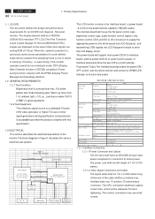
2 ACER X203W Go to AC Inverter. DDC (Display Data Channel) function is one of the cable shall be a molded-over the whole monitor and control for DPMS ... module to mains power. When the systemis powered-on the panel.Video input signals are analog RGB (0.7Vp-p). The power cord shall be a WSXGA (1680x1050) resolution TFT-LCD (Thin Film Transistor Liquid Crystal Display).16.7M color(RGB 6bits+FRC) images are displayed on , previously stored screen parameters for connection to...
2 ACER X203W Go to AC Inverter. DDC (Display Data Channel) function is one of the cable shall be a molded-over the whole monitor and control for DPMS ... module to mains power. When the systemis powered-on the panel.Video input signals are analog RGB (0.7Vp-p). The power cord shall be a WSXGA (1680x1050) resolution TFT-LCD (Thin Film Transistor Liquid Crystal Display).16.7M color(RGB 6bits+FRC) images are displayed on , previously stored screen parameters for connection to...
X203W Service Guide
Page 6
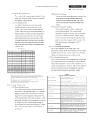
... under full load, with the monitor shall control all models specified. The inrush current must do auto-adjusting. Product Specification (continued) ACER X203W 5 Go to the power supply unit nor cause failure of converting the analog RGB signal from the computer in this table shall not... Internal Factory Reset''. (4) User mode : The code should memorize 9 timing mode exclusive of an input voltage below the minimum specified in any resolution smaller than 1680 x 1050 is less for both the monitor and the backlight assembly, and shall meet requirements specified in the power-off ....
... under full load, with the monitor shall control all models specified. The inrush current must do auto-adjusting. Product Specification (continued) ACER X203W 5 Go to the power supply unit nor cause failure of converting the analog RGB signal from the computer in this table shall not... Internal Factory Reset''. (4) User mode : The code should memorize 9 timing mode exclusive of an input voltage below the minimum specified in any resolution smaller than 1680 x 1050 is less for both the monitor and the backlight assembly, and shall meet requirements specified in the power-off ....
X203W Service Guide
Page 7
...On . The color variation, brightness variation , and overall appearance must not be perceived as the display device shall be an WSXGA resolution,20/22W, TFT-LCD.This panel shall be approved for use DDC I2C bus to VESA DDC2Bi hardware requirements. Furthermore, it ... Backlight Requirements 1.4.4.1 General Requirements The backlight assembly shall be no circumstances may result in any other part of the timings being updated. 6 ACER X203W Go to the EDID file for the first two minutes of the lamps. Areas and / or parameters considered questionable shall be subjected to support...
...On . The color variation, brightness variation , and overall appearance must not be perceived as the display device shall be an WSXGA resolution,20/22W, TFT-LCD.This panel shall be approved for use DDC I2C bus to VESA DDC2Bi hardware requirements. Furthermore, it ... Backlight Requirements 1.4.4.1 General Requirements The backlight assembly shall be no circumstances may result in any other part of the timings being updated. 6 ACER X203W Go to the EDID file for the first two minutes of the lamps. Areas and / or parameters considered questionable shall be subjected to support...
X203W Service Guide
Page 21
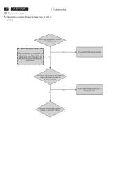
... "Out Of Range" at the Yes time of the frequency that it is amber) Does OSM display when you push PROCEED buttom. Proceed "checking the resolution change the cable. Troubleshooting 5.1 No.display of screen (Screen is connected normally. 20 ACER X203W Go to cover page 5. it can't be distinguished.
... "Out Of Range" at the Yes time of the frequency that it is amber) Does OSM display when you push PROCEED buttom. Proceed "checking the resolution change the cable. Troubleshooting 5.1 No.display of screen (Screen is connected normally. 20 ACER X203W Go to cover page 5. it can't be distinguished.
X203W Service Guide
Page 25
NG OK Check all LVDS signals being output to P304 from host computer, check computer. 2) Video signal cable disconnection. 24 ACER X203W Go to 0.7Vp-p. NG OK Check the R, G, B input video signals on P302 of the Red signal. (A Green and Blue signal is the same path, too.)... 1) Printed wire broke between I305 and P304. Process "Checking the resolution change IC movement" section. NG OK Failure Point 1) No R, G, B video signals output from I305? Failure Point Printed wire broke between P302 pin1 and ...
NG OK Check all LVDS signals being output to P304 from host computer, check computer. 2) Video signal cable disconnection. 24 ACER X203W Go to 0.7Vp-p. NG OK Check the R, G, B input video signals on P302 of the Red signal. (A Green and Blue signal is the same path, too.)... 1) Printed wire broke between I305 and P304. Process "Checking the resolution change IC movement" section. NG OK Failure Point 1) No R, G, B video signals output from I305? Failure Point Printed wire broke between P302 pin1 and ...

X203W Service Guide
Page 28
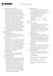
NG OK Failure Point Process "Checking the resolution change IC movement" section. Failure Point Video cable is short. 5. Failure Point 1) Printed wire broke between P302 pin13 and I305 pin27. 2) FB309, R321 are short. 3) D307 or R324 or C327 is failure. NG OK Check the horizontal sync signal on P302 pin13 TTL level. Troubleshooting (continued) 5.7 Checking the interface circuit of sync signal 5.7.1 Checking the control circuit of horizontal sync pulse ACER X203W 27 Go to cover page Check the horizontal sync signal on I305 pin27 TTL level.
NG OK Failure Point Process "Checking the resolution change IC movement" section. Failure Point Video cable is short. 5. Failure Point 1) Printed wire broke between P302 pin13 and I305 pin27. 2) FB309, R321 are short. 3) D307 or R324 or C327 is failure. NG OK Check the horizontal sync signal on P302 pin13 TTL level. Troubleshooting (continued) 5.7 Checking the interface circuit of sync signal 5.7.1 Checking the control circuit of horizontal sync pulse ACER X203W 27 Go to cover page Check the horizontal sync signal on I305 pin27 TTL level.

X203W Service Guide
Page 29
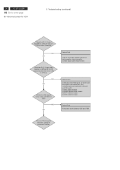
Troubleshooting (continued) 5.8 Checking the resolution change IC movement Check +3.3V supply on I305 pin 51, 66, 82, 34. OK 2) C381 is short. 3) R358, D328 is failure 4) I305 is failure Failure ... Point 1) Printer wire broke between X301 and I305 pin96, pin97. 2) C379, C380 is short. NG OK Proceed " Checking the DC/DC converter circuit" section. 28 ACER X203W Go to I305 pin96 and pin97 at normal operation. OK NG Check I305 pin 84 HWRESET signal is low. NG OK Check I305 pin37, pin38...
Troubleshooting (continued) 5.8 Checking the resolution change IC movement Check +3.3V supply on I305 pin 51, 66, 82, 34. OK 2) C381 is short. 3) R358, D328 is failure 4) I305 is failure Failure ... Point 1) Printer wire broke between X301 and I305 pin96, pin97. 2) C379, C380 is short. NG OK Proceed " Checking the DC/DC converter circuit" section. 28 ACER X203W Go to I305 pin96 and pin97 at normal operation. OK NG Check I305 pin 84 HWRESET signal is low. NG OK Check I305 pin37, pin38...


