User Manual
Page 17
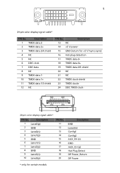
... TMDS data 0- 18 TMDS data 0+ 19 TMDS data 0/5 shield 20 NC 21 NC 22 TMDS clock shield 23 TMDS clock+ 24 DDC TMDS clock- 20-pin color display signal cable* PIN No. 5 24-pin color display signal cable* PIN No. Description 1 TMDS data 2- 2 TMDS data 2+ 3 TMDS data 2/4 shield 4 NC 5 NC 6 DDC clock...
... TMDS data 0- 18 TMDS data 0+ 19 TMDS data 0/5 shield 20 NC 21 NC 22 TMDS clock shield 23 TMDS clock+ 24 DDC TMDS clock- 20-pin color display signal cable* PIN No. 5 24-pin color display signal cable* PIN No. Description 1 TMDS data 2- 2 TMDS data 2+ 3 TMDS data 2/4 shield 4 NC 5 NC 6 DDC clock...
User Manual
Page 19
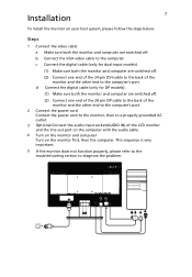
d Connect the digital cable (only for dual-input models). (1) Make sure both the monitor and computer are switched off. (2) Connect one end of the 24-pin DVI cable to the back of the LCD monitor and the line-out port on the computer with the audio cable. 4 Turn on the ...
d Connect the digital cable (only for dual-input models). (1) Make sure both the monitor and computer are switched off. (2) Connect one end of the 24-pin DVI cable to the back of the LCD monitor and the line-out port on the computer with the audio cable. 4 Turn on the ...

