
Aspire T300 Service Guide
Page 12
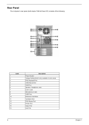
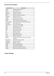
Rear Panel The computer's rear panel (both Aspire T300 & Power ST) consists of the following: Label 1 2 3 4 5 6 7 8 9 10 11 12 13 14 15 Description Power Socket Voltage Setting Switch (only available in some area) PS/2 Keyboard Port COM1/Serial Port VGA Port Speaker / Headphone Jack Line-in Jack Microphone-in Jack USB Ports Extension Card Slots Ventilation Slot PS/2 Mouse Port Printer Port Game Port LAN Port 6 Chapter 1
Rear Panel The computer's rear panel (both Aspire T300 & Power ST) consists of the following: Label 1 2 3 4 5 6 7 8 9 10 11 12 13 14 15 Description Power Socket Voltage Setting Switch (only available in some area) PS/2 Keyboard Port COM1/Serial Port VGA Port Speaker / Headphone Jack Line-in Jack Microphone-in Jack USB Ports Extension Card Slots Ventilation Slot PS/2 Mouse Port Printer Port Game Port LAN Port 6 Chapter 1
Aspire T300 Service Guide
Page 31
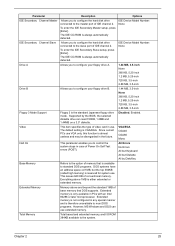
The default setting is either extended or extended memory. This leaves 640 KB of Power On Self Test errors (POST). Everything above and beyond the standard 1MB of video card in PCs with an Intel 80286 or later microprocessor. VGA/...
The default setting is either extended or extended memory. This leaves 640 KB of Power On Self Test errors (POST). Everything above and beyond the standard 1MB of video card in PCs with an Intel 80286 or later microprocessor. VGA/...
Aspire T300 Service Guide
Page 33
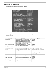
...up search sequence. This parameter allows you to specify the system Enabled boot up POST by skipping some items that are the default and suggested settings. Floppy, LS120, HDD-0, SCSI, CDROM, HDD-1, HDD-2, HDD-3, ZIP, LAN, Disabled (Disable this menu. The sequence following table ...describes the parameters found in boldface are normally checked. Parameter Virus Warning Quick Power On Self Test Hard Disk Boot Priority First/Second/Third Boot Device Boot Other Device Swap Floppy Drive Boot Up Floppy Seek Description ...
...up search sequence. This parameter allows you to specify the system Enabled boot up POST by skipping some items that are the default and suggested settings. Floppy, LS120, HDD-0, SCSI, CDROM, HDD-1, HDD-2, HDD-3, ZIP, LAN, Disabled (Disable this menu. The sequence following table ...describes the parameters found in boldface are normally checked. Parameter Virus Warning Quick Power On Self Test Hard Disk Boot Priority First/Second/Third Boot Device Boot Other Device Swap Floppy Drive Boot Up Floppy Seek Description ...
Aspire T300 Service Guide
Page 34
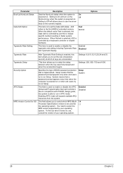
Setting to run in faster system performance. Due to compliance with PC2001 design guide, the system is able to On will turn on the Off NumLock key when the system is powered on or when end users try to the first 64KB of extended memory. Setup means that the password ... System APIC Mode This field is used to use the arrow keys on . Parameter Boot Up NumLock Status Gate A20 Option Typematic Rate Setting Description Sets the NumLock status when the system is On powered on the numeric keypad. Setting to Off will expand available IRQ resources from the system.
Setting to run in faster system performance. Due to compliance with PC2001 design guide, the system is able to On will turn on the Off NumLock key when the system is powered on or when end users try to the first 64KB of extended memory. Setup means that the password ... System APIC Mode This field is used to use the arrow keys on . Parameter Boot Up NumLock Status Gate A20 Option Typematic Rate Setting Description Sets the NumLock status when the system is On powered on the numeric keypad. Setting to Off will expand available IRQ resources from the system.
Aspire T300 Service Guide
Page 39
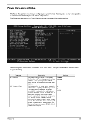
...-up event occurs. The following screen shows the Power Management parameters and their default settings: The following table describes the parameters found in boldface are the default and suggested settings. Enabled Disabled This item specifies the power saving modes for ACPI function. Parameter ACPI Function ...ACPI Suspend Type Description Options This item is a low power state. S1(POS): The S1 sleep mode is to ...
...-up event occurs. The following screen shows the Power Management parameters and their default settings: The following table describes the parameters found in boldface are the default and suggested settings. Enabled Disabled This item specifies the power saving modes for ACPI function. Parameter ACPI Function ...ACPI Suspend Type Description Options This item is a low power state. S1(POS): The S1 sleep mode is to ...
Aspire T300 Service Guide
Page 40
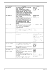
...of month) Alarm* - Blank Screen: This option only write blanks to configure the power button function. Activity of time specified in this option to set the date and time for your system. Power Off Power On Last State When enabled, any ) on . Enabled Use this field, the ...Off: During suspend mode, the monitorwill shut down . V/H SYNC+Blank: This selection will be powered down . Disabled 1~15 Mins This feature allows users to the video buffer. Disabled Enabled *Set Resume by Alarm Description Options This item is pressed for the length of selected IRQ always awakens ...
...of month) Alarm* - Blank Screen: This option only write blanks to configure the power button function. Activity of time specified in this option to set the date and time for your system. Power Off Power On Last State When enabled, any ) on . Enabled Use this field, the ...Off: During suspend mode, the monitorwill shut down . V/H SYNC+Blank: This selection will be powered down . Disabled 1~15 Mins This feature allows users to the video buffer. Disabled Enabled *Set Resume by Alarm Description Options This item is pressed for the length of selected IRQ always awakens ...

Aspire T300 Service Guide
Page 58
... POST 26h. Reserved Initial EARLY_PM_INIT switch Reserved Load keyboard matrix (notebook platform) Reserved HPM Initialization (notebook platform) Reserved 1. If ESCD is defined. Also set real-time clock power status, and then check for RTC minute. 2. Reserved Initial onboard clock generator if Early_Init_Onboard_Generator is valid, take into consideration of the ESCD's legacy information...
... POST 26h. Reserved Initial EARLY_PM_INIT switch Reserved Load keyboard matrix (notebook platform) Reserved HPM Initialization (notebook platform) Reserved 1. If ESCD is defined. Also set real-time clock power status, and then check for RTC minute. 2. Reserved Initial onboard clock generator if Early_Init_Onboard_Generator is valid, take into consideration of the ESCD's legacy information...
Aspire T300 Service Guide
Page 61
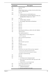
.... - If password is supported. - Auto assign ports to text mode if full screen logo is set to CMOS Initialize ISA PnP boot devices 1. If errors occur, report errors & wait for password. Call chipset power management hook. 2. Detect serial ports & parallel ports Reserved Reserved Detect & install co-processor Reserved Init... Setup & Auto-configuration table Reserved 1. Switch screen back to continue: Clear EPA or customization logo. If no errors occur or F1 key is set , ask for keys - Checkpoint 69h 6Ah 6Bh 6Ch 6Dh 6Eh 6Fh 70h 71h 72h 73h 74h 75h 76h 77h 78h 79h 7Ah 7Bh 7Ch...
.... - If password is supported. - Auto assign ports to text mode if full screen logo is set to CMOS Initialize ISA PnP boot devices 1. If errors occur, report errors & wait for password. Call chipset power management hook. 2. Detect serial ports & parallel ports Reserved Reserved Detect & install co-processor Reserved Init... Setup & Auto-configuration table Reserved 1. Switch screen back to continue: Clear EPA or customization logo. If no errors occur or F1 key is set , ask for keys - Checkpoint 69h 6Ah 6Bh 6Ch 6Dh 6Eh 6Fh 70h 71h 72h 73h 74h 75h 76h 77h 78h 79h 7Ah 7Bh 7Ch...

Aspire T300 Service Guide
Page 62
...: Build SYSID structure Reserved 1. Reserved 1. Program boot up ACPI table at top of the memory. Program P6 class write combining Update keyboard LED & typematic rate 1. Set up speed 4. Program K6 write allocation 8. Load CMOS time into DOS timer tick 5. Chipset final initialization...
...: Build SYSID structure Reserved 1. Reserved 1. Program boot up ACPI table at top of the memory. Program P6 class write combining Update keyboard LED & typematic rate 1. Set up speed 4. Program K6 write allocation 8. Load CMOS time into DOS timer tick 5. Chipset final initialization...
Aspire T300 Service Guide
Page 63
.... 4. Insert the memory modules in the check procedure. Enter BIOS Setup and load the default settings. 2. Diskette drive. 3. System board 1. Remove all power supply voltages, switch, and jumper settings before you replace the main board. IDE hard disk drive power. 4. Enter BIOS Setup to disable parity check. 2. Re-connect PS/2 keyboard and mouse. 2. PS...
.... 4. Insert the memory modules in the check procedure. Enter BIOS Setup and load the default settings. 2. Diskette drive. 3. System board 1. Remove all power supply voltages, switch, and jumper settings before you replace the main board. IDE hard disk drive power. 4. Enter BIOS Setup to disable parity check. 2. Re-connect PS/2 keyboard and mouse. 2. PS...
Aspire T300 Service Guide
Page 65
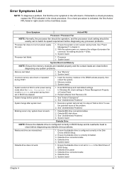
...clean before diagnosing any processor problems. Processor fan does not run but fails to enter power saving mode when the Power Management Mode is set to Enabled, and power saving timer set it to match its read/write head is indicated, the first Action/ FRU listed in...no check procedure is clean before system boot. 1. Blinking cursor only; Diskette drive power 3. System board Chapter 4 59 In Windows 98, check settings in BIOS has elapsed. 1. See "Memory" 2. System works but power supply fan runs. 1. Ensure the system is not in right column is correctly formatted...
...clean before diagnosing any processor problems. Processor fan does not run but fails to enter power saving mode when the Power Management Mode is set to Enabled, and power saving timer set it to match its read/write head is indicated, the first Action/ FRU listed in...no check procedure is clean before system boot. 1. Blinking cursor only; Diskette drive power 3. System board Chapter 4 59 In Windows 98, check settings in BIOS has elapsed. 1. See "Memory" 2. System works but power supply fan runs. 1. Ensure the system is not in right column is correctly formatted...
Aspire T300 Service Guide
Page 66
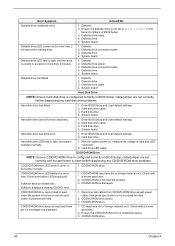
... are displayed. 1. Diskette drive 4. System board Diskette drive test failed. 1. Diskette drive 3. Hard disk drive. 4. Enter BIOS Setup and Load default settings. 2. Check with a known good disc. 2. Diskette. 2. Ensure the diskette drive is pressed and held. 1. Diskette drive connection/cable 4. Diskette drive... is turned on and its laser beam is configured correctly in the Security Options of hard disk LED connector. 2. Diskette drive power 3. CD/DVD-ROM drive CD/DVD-ROM drive LED flashes for more than 2 minutes when reading data. 1. CD may...
... are displayed. 1. Diskette drive 4. System board Diskette drive test failed. 1. Diskette drive 3. Hard disk drive. 4. Enter BIOS Setup and Load default settings. 2. Check with a known good disc. 2. Diskette. 2. Ensure the diskette drive is pressed and held. 1. Diskette drive connection/cable 4. Diskette drive... is turned on and its laser beam is configured correctly in the Security Options of hard disk LED connector. 2. Diskette drive power 3. CD/DVD-ROM drive CD/DVD-ROM drive LED flashes for more than 2 minutes when reading data. 1. CD may...
Aspire T300 Service Guide
Page 67
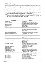
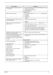
... modem adapter card to receive messages and/or fax. 1. Ensure the Modem Ring Indicator in BIOS Setup or Power Management is installed properly. 1. Ensure the modem card is set to PCI slot firmly or replace the modem card. 3. Monitor 3. System board 1. "Monitor". 2. Display problem...cannot be produced, but system sound feature works normally.) Video memory test failed. CD/DVD-ROM drive. Video adapter failed. Load default settings (if screen is readable). 3. Monitor signal connection/cable 2. Monitor signal connection/cable. 2. Display problem not listed above (including blank ...
... modem adapter card to receive messages and/or fax. 1. Ensure the Modem Ring Indicator in BIOS Setup or Power Management is installed properly. 1. Ensure the modem card is set to PCI slot firmly or replace the modem card. 3. Monitor 3. System board 1. "Monitor". 2. Display problem...cannot be produced, but system sound feature works normally.) Video memory test failed. CD/DVD-ROM drive. Video adapter failed. Load default settings (if screen is readable). 3. Monitor signal connection/cable 2. Monitor signal connection/cable. 2. Display problem not listed above (including blank ...
Aspire T300 Service Guide
Page 68
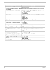
... the system). 1. Executing software shutdown from Recovery CD. No system power, or power supply fan is properly installed. Power Supply 2. Undetermined Problems 62 Chapter 4 Loop-back. 3. Printer problems. 1. Ensure the power override switch (situated at the back of Power Management is the same as the setting in BIOS Setup to Suspend. 2. Ensure the printer driver is...
... the system). 1. Executing software shutdown from Recovery CD. No system power, or power supply fan is properly installed. Power Supply 2. Undetermined Problems 62 Chapter 4 Loop-back. 3. Printer problems. 1. Ensure the power override switch (situated at the back of Power Management is the same as the setting in BIOS Setup to Suspend. 2. Ensure the printer driver is...
Aspire T300 Service Guide
Page 70
... SOCKET CPUFAN1 DIM1, DIM2 FDD1 IDE1 IDE2 IR1 J5 JP1 JP3 LED1 PANEL1 PCI1~PCI3 PWRFAN1 SPEAKER1 USB2 USB3 WOL1 WOM1 Description Accelerated Graphics Port Power connector Front audio connector Case fan connector 2 Three volt realtime clock battery Case fan connector 1 Primary CD-in connector Secondary CD-in connector Communications Networking... slots Case fan connector 2 Speaker connector Front panel USB headers Front panel USB headers Wake On LAN wakeup connector Wake On Modem wakeup connector Jumper Settings 64 Chapter 5
... SOCKET CPUFAN1 DIM1, DIM2 FDD1 IDE1 IDE2 IR1 J5 JP1 JP3 LED1 PANEL1 PCI1~PCI3 PWRFAN1 SPEAKER1 USB2 USB3 WOL1 WOM1 Description Accelerated Graphics Port Power connector Front audio connector Case fan connector 2 Three volt realtime clock battery Case fan connector 1 Primary CD-in connector Secondary CD-in connector Communications Networking... slots Case fan connector 2 Speaker connector Front panel USB headers Front panel USB headers Wake On LAN wakeup connector Wake On Modem wakeup connector Jumper Settings 64 Chapter 5
Power ST User Guide
Page 6
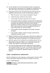
...not handled properly. Keep them away from the wall outlet and refer servicing to qualified service personnel under the following conditions: a When the power cord or plug is a laser product. AVOID EXPOSURE TO BEAM. Refer all servicing to qualified service personnel. 11 Unplug this product from ...children and dispose of used batteries promptly. 14 Use only the proper type of power supply cord set (provided in this computer is damaged or frayed b If liquid has been spilled into the product c If the product has been...
...not handled properly. Keep them away from the wall outlet and refer servicing to qualified service personnel under the following conditions: a When the power cord or plug is a laser product. AVOID EXPOSURE TO BEAM. Refer all servicing to qualified service personnel. 11 Unplug this product from ...children and dispose of used batteries promptly. 14 Use only the proper type of power supply cord set (provided in this computer is damaged or frayed b If liquid has been spilled into the product c If the product has been...
Power ST User Guide
Page 9
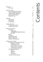
Contents Welcome iii FCC notice iii Before You Start v Important safety instructions v Laser compliance statement vi Lithium battery statement vii Setting Up The System vii Placement Tips vii Features 1 Performance 1 Multimedia 1 Connectivity 2 System Overview 3 Computer Front View 4 ...RW drive 8 Hard disk 9 Mouse 10 Keyboard 10 Speaker (Optional) 10 Monitor (Optional) 11 Modem Card (Optional) 11 Setting up your system 12 Arranging a comfortable work area 12 Adjusting your chair 12 Positioning your PC 12 Positioning your monitor 13 Positioning...
Contents Welcome iii FCC notice iii Before You Start v Important safety instructions v Laser compliance statement vi Lithium battery statement vii Setting Up The System vii Placement Tips vii Features 1 Performance 1 Multimedia 1 Connectivity 2 System Overview 3 Computer Front View 4 ...RW drive 8 Hard disk 9 Mouse 10 Keyboard 10 Speaker (Optional) 10 Monitor (Optional) 11 Modem Card (Optional) 11 Setting up your system 12 Arranging a comfortable work area 12 Adjusting your chair 12 Positioning your PC 12 Positioning your monitor 13 Positioning...
Power ST User Guide
Page 17
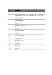
Description 1 Power Socket 2 Voltage Setting Switch (only available for STK & APP & PA) 3 PS/2 Keyboard Port 4 COM1/Serial Port 5 VGA Port 6 Speaker / Headphone Jack 7 Line-in Jack 8 Microphone-in Jack 9 USB Ports 10 Extension Card Slots 11 Ventilation Slot 12 PS/2 Mouse Port 13 Printer Port 14 Game Port 15 LAN Port 7 No.
Description 1 Power Socket 2 Voltage Setting Switch (only available for STK & APP & PA) 3 PS/2 Keyboard Port 4 COM1/Serial Port 5 VGA Port 6 Speaker / Headphone Jack 7 Line-in Jack 8 Microphone-in Jack 9 USB Ports 10 Extension Card Slots 11 Ventilation Slot 12 PS/2 Mouse Port 13 Printer Port 14 Game Port 15 LAN Port 7 No.
Power ST User Guide
Page 24
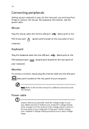
For the most part, you proceed, check the voltage range in your computer. Power cable Caution: Before you only have four things to your computer is easy. Mouse Plug the mouse cable into the the USB port (black port) ... page 13 for additonal instructions and information. If they don't match, change your computer's voltage setting according to connect: the mouse, the keyboard, the monitor, and the power cable. Make sure that it matches your computer's voltage setting (refer to the monitor manual for the location of the voltage selector switch on the...
For the most part, you proceed, check the voltage range in your computer. Power cable Caution: Before you only have four things to your computer is easy. Mouse Plug the mouse cable into the the USB port (black port) ... page 13 for additonal instructions and information. If they don't match, change your computer's voltage setting according to connect: the mouse, the keyboard, the monitor, and the power cable. Make sure that it matches your computer's voltage setting (refer to the monitor manual for the location of the voltage selector switch on the...
Power ST User Guide
Page 25
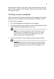
... necessary peripherals and plugging in and turned on the rear panel of the power cable into a power outlet. Note: If your computer model comes with a main power switch located above the voltage selector switch, first set the voltage selector switch to the voltage range applicable to your area before...computer. 2 On the rear panel of your computer. 15 Plug the power cable into the power cable socket located on . To turn the computer on the main power switch. 3 On the front panel of your computer, set the voltage selector switch to the voltage range applicable to work. Important:...
... necessary peripherals and plugging in and turned on the rear panel of the power cable into a power outlet. Note: If your computer model comes with a main power switch located above the voltage selector switch, first set the voltage selector switch to the voltage range applicable to your area before...computer. 2 On the rear panel of your computer. 15 Plug the power cable into the power cable socket located on . To turn the computer on the main power switch. 3 On the front panel of your computer, set the voltage selector switch to the voltage range applicable to work. Important:...


