
PD311 Service Guide
Page 7
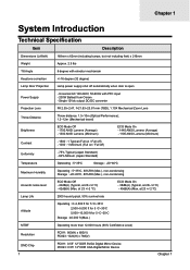
... (Typical, at 23+/-2 0C) - 42dB(A) (Max, at 23 +/-2 0C) ECO Mode On - 38dB(A) (Typical, at 23+/-2 0C) - 40dB(A) (Max, at 23 +/-2 0C) Lamp Life 2000 hours typical, 50% survival rate Altitude Operating : 0~2,500 ft for 5 oC~35oC 2,500~5,000 ft for 5 oC~30oC 5,000~10,000 ft for... oC~25oC Storage : 40,000 ft (Max.) MTBF Operating more than 12,000 hours (90% Confidence Level) Resolution PD311: 800(H) x 600(V) PD323: 1024(H) x 768(V) DMD Chip 1 PD311: 0.55" 120 DDR SVGA Digital Mirror Device PD323: 0.55" 120 DDR XGA Digital Mirror Device Chapter 1 Chapter 1 System Introduction ...
... (Typical, at 23+/-2 0C) - 42dB(A) (Max, at 23 +/-2 0C) ECO Mode On - 38dB(A) (Typical, at 23+/-2 0C) - 40dB(A) (Max, at 23 +/-2 0C) Lamp Life 2000 hours typical, 50% survival rate Altitude Operating : 0~2,500 ft for 5 oC~35oC 2,500~5,000 ft for 5 oC~30oC 5,000~10,000 ft for... oC~25oC Storage : 40,000 ft (Max.) MTBF Operating more than 12,000 hours (90% Confidence Level) Resolution PD311: 800(H) x 600(V) PD323: 1024(H) x 768(V) DMD Chip 1 PD311: 0.55" 120 DDR SVGA Digital Mirror Device PD323: 0.55" 120 DDR XGA Digital Mirror Device Chapter 1 Chapter 1 System Introduction ...

PD311 Service Guide
Page 9
Control Panel Item 1 2 3 4 5 6 7 8 9 3 Description Temp Indicator LED Lamp Indicator LED Power and Indicator LED (Power LED) Source Resync Empowering Key Menu Back Four Directional Select Keys Chapter 1
Control Panel Item 1 2 3 4 5 6 7 8 9 3 Description Temp Indicator LED Lamp Indicator LED Power and Indicator LED (Power LED) Source Resync Empowering Key Menu Back Four Directional Select Keys Chapter 1
PD311 Service Guide
Page 12
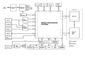
.../CLK IMAGE PROCESSING DDP2000 64 DMD CHIP Control 4 DAD1000 Control AMP. TPA0172 BEEPER PWM1 4Ω 2W Blower Fan For Lamp SYS. Ballast Control Ballast Lamp Control CW Driver PMD1000-3 Motor Control CW Index LAMP CW Motor CW INDEX SENSOR DMD CHIP 23 DAD1000 Reset ASIC IC or Chipset I/O Interface Module Fan Fan Ctrl...
.../CLK IMAGE PROCESSING DDP2000 64 DMD CHIP Control 4 DAD1000 Control AMP. TPA0172 BEEPER PWM1 4Ω 2W Blower Fan For Lamp SYS. Ballast Control Ballast Lamp Control CW Driver PMD1000-3 Motor Control CW Index LAMP CW Motor CW INDEX SENSOR DMD CHIP 23 DAD1000 Reset ASIC IC or Chipset I/O Interface Module Fan Fan Ctrl...
PD311 Service Guide
Page 16
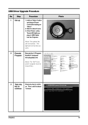
... must be closed first.) Photo 3 Type any Press any key to ue. Wait for about 5 secs. 3. Then, wait for about continue 1 minute. Once Power, Lamp, Temp LED lights up Procedure 1. The light will not function. key to contin-
... must be closed first.) Photo 3 Type any Press any key to ue. Wait for about 5 secs. 3. Then, wait for about continue 1 minute. Once Power, Lamp, Temp LED lights up Procedure 1. The light will not function. key to contin-
PD311 Service Guide
Page 18
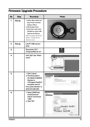
..." button and plug in the default installation directory is C:\Program Files\DLP Composer Lite 6.0 If not, press "Browse" to select the right path. 1. Once Power, Lamp, Temp LED lights up, plug in USB Cable into the Projector. (Note: The system fan will not function as well.) 2 Set-up 1. Select "Edit\Prefer...
..." button and plug in the default installation directory is C:\Program Files\DLP Composer Lite 6.0 If not, press "Browse" to select the right path. 1. Once Power, Lamp, Temp LED lights up, plug in USB Cable into the Projector. (Note: The system fan will not function as well.) 2 Set-up 1. Select "Edit\Prefer...

PD311 Service Guide
Page 26
Mechanical Disassembly Procedure 1. Photo 2 Unscrew 2 screws to remove the Lamp Cover. Chapter 3 20 Remove Lamp Module No Procedure 1 Loosen 2 tenons to remove the Lamp Module.
Mechanical Disassembly Procedure 1. Photo 2 Unscrew 2 screws to remove the Lamp Cover. Chapter 3 20 Remove Lamp Module No Procedure 1 Loosen 2 tenons to remove the Lamp Module.

PD311 Service Guide
Page 31
6. Remove Right Cover Module / Front Cover Module No Procedure 1 Unscrew 1 screw to remove the IR Board in the Right Cover Module 3 Loosen 2 tenons to disassemble the Right Cover Module and Front Cover Module. Photo 2 Unscrew 2 screws to remove the Lamp Blower / Air Duct in the Front Cover Module. 25 Chapter 3
6. Remove Right Cover Module / Front Cover Module No Procedure 1 Unscrew 1 screw to remove the IR Board in the Right Cover Module 3 Loosen 2 tenons to disassemble the Right Cover Module and Front Cover Module. Photo 2 Unscrew 2 screws to remove the Lamp Blower / Air Duct in the Front Cover Module. 25 Chapter 3

PD311 Service Guide
Page 34
Remove Blower / DC DC / Bottom Cover Module No Procedure 1 Remove Blower / DC DC: (1) Unscrew 3 screws to -lamp connector moduel Chapter 3 28 Photo The direction should be heading forward Notice: Please ensure the blue wire arrangement (The direction should be heading forward as... assembling the DC DC Module. (1) Blower (2) Unscrew 1 screw to remove the DC DC Module. 2 Remove the Bottom Cover: (1) Unscrew 1 screw to remove the Ballast-to-lamp connector Module (2) DC DC Module (2) Elevator Foot (2) Unscrew 1 screw to remove the Elevator Foot. (1) Ballast-to remove the Blower. 9.
Remove Blower / DC DC / Bottom Cover Module No Procedure 1 Remove Blower / DC DC: (1) Unscrew 3 screws to -lamp connector moduel Chapter 3 28 Photo The direction should be heading forward Notice: Please ensure the blue wire arrangement (The direction should be heading forward as... assembling the DC DC Module. (1) Blower (2) Unscrew 1 screw to remove the DC DC Module. 2 Remove the Bottom Cover: (1) Unscrew 1 screw to remove the Ballast-to-lamp connector Module (2) DC DC Module (2) Elevator Foot (2) Unscrew 1 screw to remove the Elevator Foot. (1) Ballast-to remove the Blower. 9.

PD311 Service Guide
Page 35
... Chapter 3 The direction should be heading forward (1) Screw 3 screws to assemble the Blower. Photo (1) Elevator Foot (2) Screw 1 screw to assemble the Ballast-to-lamp connector Module (2) Ballast-to-lamp connector moduel 2 Assemble DC DC / Blower: (1) Screw 1 screw to assemble the Elevator Foot. Mechanical Reassembly Procedure 1. Assemble Bottom Cover Module / DC DC / Blower...
... Chapter 3 The direction should be heading forward (1) Screw 3 screws to assemble the Blower. Photo (1) Elevator Foot (2) Screw 1 screw to assemble the Ballast-to-lamp connector Module (2) Ballast-to-lamp connector moduel 2 Assemble DC DC / Blower: (1) Screw 1 screw to assemble the Elevator Foot. Mechanical Reassembly Procedure 1. Assemble Bottom Cover Module / DC DC / Blower...

PD311 Service Guide
Page 38
Assemble Front Cover Module / Right Cover Module No Procedure 1 Fasten 2 tenons to assemble the Right Cover Module and Front Cover Module. Chapter 3 32 Photo 2 Screw 2 screws to assemble the Lamp Blower / Air Duct in the Right Cover Module 3 Screw 1 screw to assemble the IR Board in the Front Cover Module. 4.
Assemble Front Cover Module / Right Cover Module No Procedure 1 Fasten 2 tenons to assemble the Right Cover Module and Front Cover Module. Chapter 3 32 Photo 2 Screw 2 screws to assemble the Lamp Blower / Air Duct in the Right Cover Module 3 Screw 1 screw to assemble the IR Board in the Front Cover Module. 4.

PD311 Service Guide
Page 43
9. Assemble Lamp Module No Procedure 1 Screw 2 screws to assemble the Lamp Cover. 37 Chapter 3 Photo 2 Fasten 2 tenons to assemble the Lamp Module.
9. Assemble Lamp Module No Procedure 1 Screw 2 screws to assemble the Lamp Cover. 37 Chapter 3 Photo 2 Fasten 2 tenons to assemble the Lamp Module.

PD311 Service Guide
Page 44
... on Power off (Cooling State I) Power off (Cooling State II) Power off (Cooling Completed) Error (Over Temp.) Error (Fan lock fail) Error (Lamp fail) Blue O O O O O O O Power LED Red Temp Lamp LED LED Blinking 1 sec on / 1 sec off O O O O O Blinking 0.5 sec on / 0.5 sec off O O Blinking 1 sec on / 1 sec off but Fan on O O (Can be...
... on Power off (Cooling State I) Power off (Cooling State II) Power off (Cooling Completed) Error (Over Temp.) Error (Fan lock fail) Error (Lamp fail) Blue O O O O O O O Power LED Red Temp Lamp LED LED Blinking 1 sec on / 1 sec off O O O O O Blinking 0.5 sec on / 0.5 sec off O O Blinking 1 sec on / 1 sec off but Fan on O O (Can be...
PD311 Service Guide
Page 45
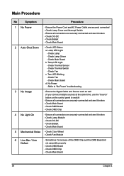
...and AC Power Outlet are securely connected and aren't broken - Check DC-DC - Check Lamp Driver - Temp LED Light - Check Fan c. Check DMD Board - Check DMD Chip 4 No Light On - Check Lamp Module - Check Ballast - Check Color Wheel - Check Ballast - Check LED Status a. ...Check Thermal Sensor - Tem LED Blinking - Ensure all connectors are securely connected and aren't broken - Lamp LED Light - Check DMD Board - Check Lamp Cover and Interrupt Switch - Check Thermal Switch - Check DC-DC - Check DMD Chip - Check Main Board 2 Auto Shut Down...
...and AC Power Outlet are securely connected and aren't broken - Check DC-DC - Check Lamp Driver - Temp LED Light - Check Fan c. Check DMD Board - Check DMD Chip 4 No Light On - Check Lamp Module - Check Ballast - Check Color Wheel - Check Ballast - Check LED Status a. ...Check Thermal Sensor - Tem LED Blinking - Ensure all connectors are securely connected and aren't broken - Lamp LED Light - Check DMD Board - Check Lamp Cover and Interrupt Switch - Check Thermal Switch - Check DC-DC - Check DMD Chip - Check Main Board 2 Auto Shut Down...
PD311 Service Guide
Page 46
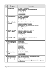
... dirt - Check Battery b. Check Remote Control c. Ensure the Signal Cable and Source work as well - Check Lamp Module - Check Main Board - Check Main Board - Check Color Wheel - Ensure the Brightness is within spec. (Replace the Lamp if the Brightness is clean - Check Engine Module - Check Main Board - Check DMD Board - IR Receiver...
... dirt - Check Battery b. Check Remote Control c. Ensure the Signal Cable and Source work as well - Check Lamp Module - Check Main Board - Check Main Board - Check Color Wheel - Ensure the Brightness is within spec. (Replace the Lamp if the Brightness is clean - Check Engine Module - Check Main Board - Check DMD Board - IR Receiver...
PD311 Service Guide
Page 47
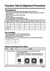
After repairing each PD311 / PD323, the unit should be burn-in Time Normal Repair 2 Hours NFF 4 Hours Auto Shutdown 6 Hours Guide to Entering Service Mode No Item Steps 1.... (As the following steps to the table below . Charge Parts/Update Version Update Color Wheel Index ADC Calibration Video Calibration Reset Lamp Use Time Factory Reset EDID M/B v v v v v v FW v v v Color Wheel v Lamp Module v Test Condition - Minolta CL-100 - After changing parts, check the information below ). Function Test & Alignment Procedure Test Equipment - ...
After repairing each PD311 / PD323, the unit should be burn-in Time Normal Repair 2 Hours NFF 4 Hours Auto Shutdown 6 Hours Guide to Entering Service Mode No Item Steps 1.... (As the following steps to the table below . Charge Parts/Update Version Update Color Wheel Index ADC Calibration Video Calibration Reset Lamp Use Time Factory Reset EDID M/B v v v v v v FW v v v Color Wheel v Lamp Module v Test Condition - Minolta CL-100 - After changing parts, check the information below ). Function Test & Alignment Procedure Test Equipment - ...

PD311 Service Guide
Page 52
... PD311 ASSY TOP COVER MODULE PD311 ASSY ENGINE MODULE PD311 4 70.85M14G001 ASSY LAMP MODULE PD311 5 70.85M04G001 6 70.85M05G001 7 70.85M06G001 8 70.85M07G001 ASSY REAR COVER MODULE PD311 ASSY LEFT SIDE COVER MODULE PD311 ASSY RIGHT SIDE COVER MODULE PD311 ASSY FRONT COVER MODULE PD311 9 70.85M15G001 ASSY ROD MODULE PD311 ...AL5052 0.3t DP715 24 52.85M02G001 SYSTEM RUBBER FOR TOP COVER RUBBER PD311 25 41.85M09G001 EMI GASKET W13*L13*H2 mm ,|9mm 26 70.85M20G001 27 85.1A326G060 ASSY LAMP COVER MODULE PD311 SCREW PAN HEAD MECH M2.6*6 BLACK Note: Please refer to RSPL for...
... PD311 ASSY TOP COVER MODULE PD311 ASSY ENGINE MODULE PD311 4 70.85M14G001 ASSY LAMP MODULE PD311 5 70.85M04G001 6 70.85M05G001 7 70.85M06G001 8 70.85M07G001 ASSY REAR COVER MODULE PD311 ASSY LEFT SIDE COVER MODULE PD311 ASSY RIGHT SIDE COVER MODULE PD311 ASSY FRONT COVER MODULE PD311 9 70.85M15G001 ASSY ROD MODULE PD311 ...AL5052 0.3t DP715 24 52.85M02G001 SYSTEM RUBBER FOR TOP COVER RUBBER PD311 25 41.85M09G001 EMI GASKET W13*L13*H2 mm ,|9mm 26 70.85M20G001 27 85.1A326G060 ASSY LAMP COVER MODULE PD311 SCREW PAN HEAD MECH M2.6*6 BLACK Note: Please refer to RSPL for...

PD311 Service Guide
Page 54
...48 Exploded Parts List Item Part Number Description 1 61.82Y18G002 2 70.85M12G001 3 70.85M09G001 BOTTOM CASE MG ALLOY DP715 ASSY BLOWER4520 MODULE PD311 ASSY DC-DC MODULE PD311 4 70.82Y07G001 ASSY BALLAST MODULE DP715 5 70.82Y14G001 6 85.1A526G050 7 61.82Y25G001 8 51.82Y14G001 ASSY ELEVATOR MODULE DP715 SCREW PAN... 9 51.82Y15G001 BALLAST CNNT LOCK PPS DP715 10 42.82Y03G001 11 51.80J33G001 12 61.00022G001 13 85.1C227G050 W.A. 2P BALLAST TO LAMP PLASTIC SCREW PC M3*8 X5.7mm PG-S-308 VULCAN-1 SELF-LOCKING RING (SPN p1.5) SCREW PAN MECH M3.5*5 COLOR (W/SP WASHER)...
...48 Exploded Parts List Item Part Number Description 1 61.82Y18G002 2 70.85M12G001 3 70.85M09G001 BOTTOM CASE MG ALLOY DP715 ASSY BLOWER4520 MODULE PD311 ASSY DC-DC MODULE PD311 4 70.82Y07G001 ASSY BALLAST MODULE DP715 5 70.82Y14G001 6 85.1A526G050 7 61.82Y25G001 8 51.82Y14G001 ASSY ELEVATOR MODULE DP715 SCREW PAN... 9 51.82Y15G001 BALLAST CNNT LOCK PPS DP715 10 42.82Y03G001 11 51.80J33G001 12 61.00022G001 13 85.1C227G050 W.A. 2P BALLAST TO LAMP PLASTIC SCREW PC M3*8 X5.7mm PG-S-308 VULCAN-1 SELF-LOCKING RING (SPN p1.5) SCREW PAN MECH M3.5*5 COLOR (W/SP WASHER)...

PD311 Service Guide
Page 55
...TOP IR PC PD311 SCREW DUBLE FLAT MECH M2.6*3 Ni NYLOK PCBA KEYPAD BD FOR PD311 FFC 20P P=0.5mm MAIN BOARD TO KEYPAD BOARD PD311 EMI GASKET W10*H10*L40mm SPONG FOR TOP COVER 1 PD311 SPONG FOR TOP COVER 2 PD311 TOP COVER AL FOIL 1 WITH F12 PD311 TOP COVER AL FOIL 2 WITH F12 PD311 LAMP HEAT PLATE ...AL PD311 Note: Please refer to RSPL for updated...
...TOP IR PC PD311 SCREW DUBLE FLAT MECH M2.6*3 Ni NYLOK PCBA KEYPAD BD FOR PD311 FFC 20P P=0.5mm MAIN BOARD TO KEYPAD BOARD PD311 EMI GASKET W10*H10*L40mm SPONG FOR TOP COVER 1 PD311 SPONG FOR TOP COVER 2 PD311 TOP COVER AL FOIL 1 WITH F12 PD311 TOP COVER AL FOIL 2 WITH F12 PD311 LAMP HEAT PLATE ...AL PD311 Note: Please refer to RSPL for updated...

PD311 Service Guide
Page 68
... PPS AR04 LT20 SCREW PAN MECH M2.6*5 Ni NYLON LAMP FIX SPRING SUS301 0.2T DP715 LAMP LIGHTCUT MG ALLOY 0.5T DP715 LAMP HOLDER MG ALLOY DP715 LAMP HOUSING SHOULDER SCREW M2.6*8-3L Ni 82Y LAMP CHANGER HANDLE SUS304 1.6d DP725 SPONG 1 FOR LAMP F12 PD311 SPONG 3 FOR LAMP F12 PD311 Note: Please refer to RSPL for updated Part Number...
... PPS AR04 LT20 SCREW PAN MECH M2.6*5 Ni NYLON LAMP FIX SPRING SUS301 0.2T DP715 LAMP LIGHTCUT MG ALLOY 0.5T DP715 LAMP HOLDER MG ALLOY DP715 LAMP HOUSING SHOULDER SCREW M2.6*8-3L Ni 82Y LAMP CHANGER HANDLE SUS304 1.6d DP725 SPONG 1 FOR LAMP F12 PD311 SPONG 3 FOR LAMP F12 PD311 Note: Please refer to RSPL for updated Part Number...

PD311 Service Guide
Page 70
Chapter 5 64 ASSY ENGINE BASE MODULE (PD311) Exploded Parts List Item 1 2 3 4 5 6 7 8 9 10 Part Number 52.82Y02G001 51.82Y28G001 61.82Y01G001 52.82Y03G001 61.82Y09G001 85.1A526G050 87.FL030G008 23.80S10G001 61.80J02G001 ... PAN MECH M2.6*5 Ni NYLON WASHER FLAT 7*3.1*0.8t PC PINGOOD WS-1M UV/IR FILTER OF DP739 SERIES UVIR HOLDER 739 SUS301 0.3t SPONG 2 FOR LAMP F12 PD311 Note: Please refer to RSPL for updated Part Number.
Chapter 5 64 ASSY ENGINE BASE MODULE (PD311) Exploded Parts List Item 1 2 3 4 5 6 7 8 9 10 Part Number 52.82Y02G001 51.82Y28G001 61.82Y01G001 52.82Y03G001 61.82Y09G001 85.1A526G050 87.FL030G008 23.80S10G001 61.80J02G001 ... PAN MECH M2.6*5 Ni NYLON WASHER FLAT 7*3.1*0.8t PC PINGOOD WS-1M UV/IR FILTER OF DP739 SERIES UVIR HOLDER 739 SUS301 0.3t SPONG 2 FOR LAMP F12 PD311 Note: Please refer to RSPL for updated Part Number.


