
PD100 and PD120 Service Guide
Page 7
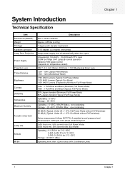
...000 ft (Max.) Operating more than 12,000 hours (90% Confidence Level) 1 Chapter 1 Eco Mode) 1300 ANSI Lumens (Engineering Minimum; Full Power Mode without DVD/wireless) Noise measurement follows ISO7779, A-weighted sound pressure level measurement, 7200 rpm color wheel rotational speed 1500 hours min, 50% ...survival rate (Full Power Mode) 2000 hours min, 50% survival rate (Eco Mode) Operating : 0~2,500 ft for 5 oC~35oC 2,500~5,000 ft for 5 oC...
...000 ft (Max.) Operating more than 12,000 hours (90% Confidence Level) 1 Chapter 1 Eco Mode) 1300 ANSI Lumens (Engineering Minimum; Full Power Mode without DVD/wireless) Noise measurement follows ISO7779, A-weighted sound pressure level measurement, 7200 rpm color wheel rotational speed 1500 hours min, 50% ...survival rate (Full Power Mode) 2000 hours min, 50% survival rate (Eco Mode) Operating : 0~2,500 ft for 5 oC~35oC 2,500~5,000 ft for 5 oC...
PD100 and PD120 Service Guide
Page 9
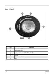
Control Panel Item 1 2 3 4 5 6 7 Description Lamp Indicator LED Temp Indicator LED Power / Standby and Indicator LED (Power LED) Source Resync Four Directional Select Keys Menu 3 Chapter 1
Control Panel Item 1 2 3 4 5 6 7 Description Lamp Indicator LED Temp Indicator LED Power / Standby and Indicator LED (Power LED) Source Resync Four Directional Select Keys Menu 3 Chapter 1
PD100 and PD120 Service Guide
Page 11
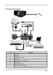
Connecting the Projector Item 1 2 3 4 5 6 7 8 9 5 Description Power Cord VGA Cable Composite Video Cable USB Cable VGA to Component / HDTV Adapter S-Video Cable Audio Cable Jack / Jack DVI Cable (Optional Accessory) 5V DC Output Jack for attached Dongle Device (for PD100 only) (for PD120 only) Chapter 1
Connecting the Projector Item 1 2 3 4 5 6 7 8 9 5 Description Power Cord VGA Cable Composite Video Cable USB Cable VGA to Component / HDTV Adapter S-Video Cable Audio Cable Jack / Jack DVI Cable (Optional Accessory) 5V DC Output Jack for attached Dongle Device (for PD100 only) (for PD120 only) Chapter 1
PD100 and PD120 Service Guide
Page 12
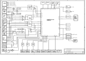
... HVSync WS HVSync HV 2 / 9883A 1 / SCART Sync 2 / RGB 3 / 8 / S-Video CVBS Video Decoder 8 / Digital UV Digital Y Image Processor DDP2000 DDR Data CHIP 64 / (DDR) 2 IN / 2 SAA7117A 4 Power Sense / / DVD S-Video DVD CVBS / Ctrl/CLK Reset IC USB IN Audio IN R/L 1 2 / 2 Vol ADJ AMP / 2 / 2 /+ LPF AMP D656EN# 8 Data / 1 Clock / USB D+/DBEEP RIR DAT...
... HVSync WS HVSync HV 2 / 9883A 1 / SCART Sync 2 / RGB 3 / 8 / S-Video CVBS Video Decoder 8 / Digital UV Digital Y Image Processor DDP2000 DDR Data CHIP 64 / (DDR) 2 IN / 2 SAA7117A 4 Power Sense / / DVD S-Video DVD CVBS / Ctrl/CLK Reset IC USB IN Audio IN R/L 1 2 / 2 Vol ADJ AMP / 2 / 2 /+ LPF AMP D656EN# 8 Data / 1 Clock / USB D+/DBEEP RIR DAT...
PD100 and PD120 Service Guide
Page 13
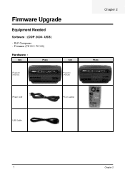
USB) - DLP Composer - Firmware (PD100 / PD120) Hardware : Item Photo Item Projector (PD100) Projector (PD120) Chapter 2 Photo Power Cord PC or Laptop USB Cable 7 Chapter 2 Firmware Upgrade Equipment Needed Software : (DDP 2000-
USB) - DLP Composer - Firmware (PD100 / PD120) Hardware : Item Photo Item Projector (PD100) Projector (PD120) Chapter 2 Photo Power Cord PC or Laptop USB Cable 7 Chapter 2 Firmware Upgrade Equipment Needed Software : (DDP 2000-
PD100 and PD120 Service Guide
Page 16
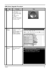
Plug in Power Cord. 3. Hold on "Menu" button and then plug in USB Cable into the Projector. 2. Chapter2 10 USB Driver Upgrade Procedure No Step 1 Set-up Procedure 1. continue Then, wait for about 1 minute. Wait for about 5 seconds. (Note: The system fan will not function as well.) 2 Execute Program Execute the C:\Program files\DLP Composer\usbupdata.cmd. (Note: The "DLP Composer" program must be closed first.) Photo 3 Type any key to Type any key to continue. The light will not function.
Plug in Power Cord. 3. Hold on "Menu" button and then plug in USB Cable into the Projector. 2. Chapter2 10 USB Driver Upgrade Procedure No Step 1 Set-up Procedure 1. continue Then, wait for about 1 minute. Wait for about 5 seconds. (Note: The system fan will not function as well.) 2 Execute Program Execute the C:\Program files\DLP Composer\usbupdata.cmd. (Note: The "DLP Composer" program must be closed first.) Photo 3 Type any key to Type any key to continue. The light will not function.
PD100 and PD120 Service Guide
Page 20
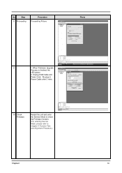
No Step 8 Proceeding Procedure Proceeding Picture Photo 9 1. Re-plug in Power Cable after 3 mins. 10 Check Firmware Restart the unit and enter the Service Mode to check the Firmware Version. (For entering Service Mode, please refer to Chapter 4 Function Test and Alignment Procedure.) Chapter2 14 When Firmware Upgrade Process is finished, the LED power 2. Unplug USB Cable and Power Cord.
No Step 8 Proceeding Procedure Proceeding Picture Photo 9 1. Re-plug in Power Cable after 3 mins. 10 Check Firmware Restart the unit and enter the Service Mode to check the Firmware Version. (For entering Service Mode, please refer to Chapter 4 Function Test and Alignment Procedure.) Chapter2 14 When Firmware Upgrade Process is finished, the LED power 2. Unplug USB Cable and Power Cord.
PD100 and PD120 Service Guide
Page 21
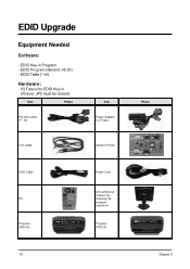
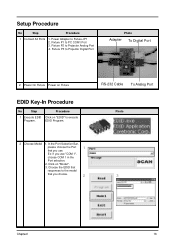
EDID Upgrade Equipment Needed Software: - V3 Fixture for checking the program execution) Projector (PD120) 15 Photo Chapter 2 EDID Table (*.ini) Hardware: - EDID Key-in (Fixture: JP3 must be closed) Item Photo RS-232 Cable (F - M) Item Power Adapter for Fixture DVI Cable Generic Fixture VGA Cable PC Projector (PD100) Power Cord One additional monitor (for EDID Key-in Program - EDID Program (Generic V0.51) -
EDID Upgrade Equipment Needed Software: - V3 Fixture for checking the program execution) Projector (PD120) 15 Photo Chapter 2 EDID Table (*.ini) Hardware: - EDID Key-in (Fixture: JP3 must be closed) Item Photo RS-232 Cable (F - M) Item Power Adapter for Fixture DVI Cable Generic Fixture VGA Cable PC Projector (PD100) Power Cord One additional monitor (for EDID Key-in Program - EDID Program (Generic V0.51) -
PD100 and PD120 Service Guide
Page 22
... Photo 2 Choose Model 1. Fixture P3 to Fixture JP1 2. Setup Procedure No Step Procedure 1 Connect All Ports 1. Fixture P2 to PC COM1 Port 3. EDID Program. Power On Fixture Power on Fixture EDID Key-In Procedure No Step Procedure 1 Execute EDID Click on "Model". 3. Click on "EDID" to the model that you choose. 2 3 Chapter2...
... Photo 2 Choose Model 1. Fixture P3 to Fixture JP1 2. Setup Procedure No Step Procedure 1 Connect All Ports 1. Fixture P2 to PC COM1 Port 3. EDID Program. Power On Fixture Power on Fixture EDID Key-In Procedure No Step Procedure 1 Execute EDID Click on "Model". 3. Click on "EDID" to the model that you choose. 2 3 Chapter2...
PD100 and PD120 Service Guide
Page 25
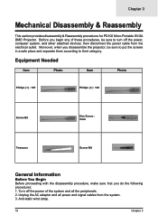
...of these procedures, be sure to put the screws in a safe place and separate them according to turn off the power of the system and all power and signal cables from the electrical outlet. Moreover, when you do the following procedures: 1. Unplug the AC adapter and... the disassembly procedure, make sure that you disassemble the projector, be sure to their category. then disconnect the power cable from the system. 3. Turn off the power, computer system, and other attached devices; Chapter 3 Mechanical Disassembly & Reassembly This section provides disassembly & Reassembly procedures ...
...of these procedures, be sure to put the screws in a safe place and separate them according to turn off the power of the system and all power and signal cables from the electrical outlet. Moreover, when you do the following procedures: 1. Unplug the AC adapter and... the disassembly procedure, make sure that you disassemble the projector, be sure to their category. then disconnect the power cable from the system. 3. Turn off the power, computer system, and other attached devices; Chapter 3 Mechanical Disassembly & Reassembly This section provides disassembly & Reassembly procedures ...
PD100 and PD120 Service Guide
Page 53
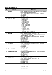
...not assemble properly - Adjust Color Wheel Index - Check Main Board - Temp LED Light - Check Thermal Switch - Check Photo Sensor d. No Power - Ensure all connectors are securely connected and aren't broken - Check DC-DC - Check DMD Chip - Check Main Board - Check Main Board... - Color Wheel - Check Main Board - Check DMD Board - Ensure the Signal Cable and Source work as well - Ensure the Power Cord and AC Power Outlet are securely connected and aren't broken - Check Ballast - Check Main Board - Ensure all connectors are securely connected - Check Ballast...
...not assemble properly - Adjust Color Wheel Index - Check Main Board - Temp LED Light - Check Thermal Switch - Check Photo Sensor d. No Power - Ensure all connectors are securely connected and aren't broken - Check DC-DC - Check DMD Chip - Check Main Board - Check Main Board... - Color Wheel - Check Main Board - Check DMD Board - Ensure the Signal Cable and Source work as well - Ensure the Power Cord and AC Power Outlet are securely connected and aren't broken - Check Ballast - Check Main Board - Ensure all connectors are securely connected - Check Ballast...
PD100 and PD120 Service Guide
Page 59
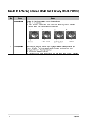
..." to enter Service Mode: 1. Guide to Entering Service Mode and Factory Reset (PD100) No Item 1 Service Mode Steps Please do the following steps to see if it works. 53 Chapter 4 The following pictures show) 1 2 3 4 Power "Left"button "Left"button Menu 2 Factory Reset After final QC step, we have... to erase all saved change again and restore the factory defaults. Press "Power", "Left" button, "Left" button and "Menu" by order to enter the Service Mode. (As the following actions will allow you to erase...
..." to enter Service Mode: 1. Guide to Entering Service Mode and Factory Reset (PD100) No Item 1 Service Mode Steps Please do the following steps to see if it works. 53 Chapter 4 The following pictures show) 1 2 3 4 Power "Left"button "Left"button Menu 2 Factory Reset After final QC step, we have... to erase all saved change again and restore the factory defaults. Press "Power", "Left" button, "Left" button and "Menu" by order to enter the Service Mode. (As the following actions will allow you to erase...

PD100 and PD120 Service Guide
Page 67
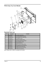
PD100 Assy Top Cover Module Exploded Parts List Item 1 2 3 Part Number 51.82V03G001 61.82V04G001 51.82Q03G001 Description TOP COVER PC+ABS PD120 TOP COVER SHIELDING SPTE PD120 KEYPAD MAIN BUTTON PC+ABS PD322 4 51.82Q05G001 5 51.82Q06G001 6 80.82Q03G001 7 61.82V03G001 8 85.WA123.040 9 42.82V02G001 LED HOUSING PC PD322 POWER LED...
PD100 Assy Top Cover Module Exploded Parts List Item 1 2 3 Part Number 51.82V03G001 61.82V04G001 51.82Q03G001 Description TOP COVER PC+ABS PD120 TOP COVER SHIELDING SPTE PD120 KEYPAD MAIN BUTTON PC+ABS PD322 4 51.82Q05G001 5 51.82Q06G001 6 80.82Q03G001 7 61.82V03G001 8 85.WA123.040 9 42.82V02G001 LED HOUSING PC PD322 POWER LED...
PD100 and PD120 Service Guide
Page 68
... SPTE PD120 KEYPAD MAIN BUTTON PC+ABS PD322 4 51.82Q05G001 5 51.82Q06G001-B 6 80.82Q03G001 7 61.82V03G001 8 85.WA123.040 9 42.82V02G001 LED HOUSING PC PD322 POWER LED HOUSING PC PD322 PCBA KEYPAD BOARD PD322 ''GREEN'' KEYPAD SHIELDING AL PD120 SCREW PAN TAP M3*4 Ni CABLE FFC 14P P=0.5 120mm PD120 10 51...
... SPTE PD120 KEYPAD MAIN BUTTON PC+ABS PD322 4 51.82Q05G001 5 51.82Q06G001-B 6 80.82Q03G001 7 61.82V03G001 8 85.WA123.040 9 42.82V02G001 LED HOUSING PC PD322 POWER LED HOUSING PC PD322 PCBA KEYPAD BOARD PD322 ''GREEN'' KEYPAD SHIELDING AL PD120 SCREW PAN TAP M3*4 Ni CABLE FFC 14P P=0.5 120mm PD120 10 51...
PD100 Quick Start Guide
Page 1
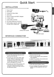
...end of the VGA cable to the "VGA In" connector on the projector first and then the computer. 3. Powering On the Projector Powering On the Projector 1. Run you presentation. Press the power button twice. 2. Composite Video Cable 4. Turn on the projector; USB Cable 5. connect the other end to a... Component/HDTV Adapter 6. VGA to the VGA connector on the projector; Do not remote AC power cord from outlet until the projector fan shut down. Power Cord 2. S-Video Cable 7. Connect one end of the power cord into the AC power socket on the computer and tighten the screws. 3.
...end of the VGA cable to the "VGA In" connector on the projector first and then the computer. 3. Powering On the Projector Powering On the Projector 1. Run you presentation. Press the power button twice. 2. Composite Video Cable 4. Turn on the projector; USB Cable 5. connect the other end to a... Component/HDTV Adapter 6. VGA to the VGA connector on the projector; Do not remote AC power cord from outlet until the projector fan shut down. Power Cord 2. S-Video Cable 7. Connect one end of the power cord into the AC power socket on the computer and tighten the screws. 3.
PD100 User's Guide
Page 1
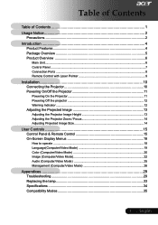
... Overview 5 Product Overview 6 Main Unit...6 Control Panel ...7 Connection Ports ...8 Remote Control with Laser Pointer 9 Installation 10 Connecting the Projector 10 Powering On/Off the Projector 11 Powering On the Projector 11 Powering Off the projector 12 Warning Indicator ...12 Adjusting the Projected Image 13 Adjusting the Projector Image Height 13 Adjusting the Projector...
... Overview 5 Product Overview 6 Main Unit...6 Control Panel ...7 Connection Ports ...8 Remote Control with Laser Pointer 9 Installation 10 Connecting the Projector 10 Powering On/Off the Projector 11 Powering On the Projector 11 Powering Off the projector 12 Warning Indicator ...12 Adjusting the Projected Image 13 Adjusting the Projector Image Height 13 Adjusting the Projector...
PD100 User's Guide
Page 2
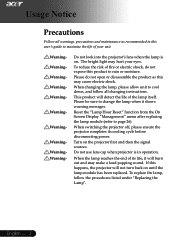
... in this product to cool down, and follow the procedures listed under "Replacing the Lamp". To reduce the risk of its cooling cycle before disconnecting power. Usage Notice Precautions Follow all changing instructions. This product will not turn back on the projector first and then the signal sources.
... in this product to cool down, and follow the procedures listed under "Replacing the Lamp". To reduce the risk of its cooling cycle before disconnecting power. Usage Notice Precautions Follow all changing instructions. This product will not turn back on the projector first and then the signal sources.
PD100 User's Guide
Page 3
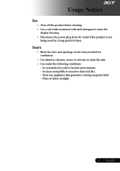
... Notice Do: Turn off the product before cleaning. Use a soft cloth moistened with mild detergent to clean the display housing. Disconnect the power plug from AC outlet if the product is not being used for ventilation. Use abrasive cleaners, waxes or solvents to excessive dust and dirt...
... Notice Do: Turn off the product before cleaning. Use a soft cloth moistened with mild detergent to clean the display housing. Disconnect the power plug from AC outlet if the product is not being used for ventilation. Use abrasive cleaners, waxes or solvents to excessive dust and dirt...
PD100 User's Guide
Page 5
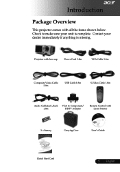
Contact your unit is missing. Projector with lens cap Power Cord 1.8m VGA Cable 1.8m Composite Video Cable 2.0m USB Cable 1.8m S-Video Cable 1.8m Audio Cable Jack /Jack VGA to make sure your dealer immediately if anything is complete. English Introduction Package Overview This projector comes with Laser Pointer 2 x Battery Carrying Case User's Guide Quick Start Card 5 ... Check to Component/ 1.8m HDTV Adapter Remote Control with all the items shown below.
Contact your unit is missing. Projector with lens cap Power Cord 1.8m VGA Cable 1.8m Composite Video Cable 2.0m USB Cable 1.8m S-Video Cable 1.8m Audio Cable Jack /Jack VGA to make sure your dealer immediately if anything is complete. English Introduction Package Overview This projector comes with Laser Pointer 2 x Battery Carrying Case User's Guide Quick Start Card 5 ... Check to Component/ 1.8m HDTV Adapter Remote Control with all the items shown below.
PD100 User's Guide
Page 6
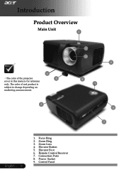
Focus Ring 2. Control Panel The color of the projector 5 cover in this menu is subject to change depending on marketing announcement. 2 1 3 8 4 9 6 7 English ... 6 1. Zoom Lens 4. Elevator Foot 6. Remote Control Receiver 7. Power Socket 9. Connection Ports 8. Elevator Button 5. Zoom Ring 3. Introduction Product Overview Main Unit 2 6 The color of real product is for reference only.
Focus Ring 2. Control Panel The color of the projector 5 cover in this menu is subject to change depending on marketing announcement. 2 1 3 8 4 9 6 7 English ... 6 1. Zoom Lens 4. Elevator Foot 6. Remote Control Receiver 7. Power Socket 9. Connection Ports 8. Elevator Button 5. Zoom Ring 3. Introduction Product Overview Main Unit 2 6 The color of real product is for reference only.


