
User Manual
Page 11
... LCD monitors iii Cleaning your monitor iii Connecting/disconnecting the device iii Accessibility iv Safe listening iv Warnings iv Using electrical power iv Product servicing v Additional safety information vi IT Equipment Recycling Information vi Disposal instructions vi LCD...pin assignment 5 15-pin color display signal cable 5 24-pin color display signal cable 6 19-pin color display signal cable* 6 Standard timing table 7 Installation 8 Users controls 9 Front panel controls 9 Acer eColor Management 10 Operation instructions 10 Features and benefits 10...
... LCD monitors iii Cleaning your monitor iii Connecting/disconnecting the device iii Accessibility iv Safe listening iv Warnings iv Using electrical power iv Product servicing v Additional safety information vi IT Equipment Recycling Information vi Disposal instructions vi LCD...pin assignment 5 15-pin color display signal cable 5 24-pin color display signal cable 6 19-pin color display signal cable* 6 Standard timing table 7 Installation 8 Users controls 9 Front panel controls 9 Acer eColor Management 10 Operation instructions 10 Features and benefits 10...
User Manual
Page 17
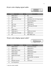
5 24-pin color display signal cable English PIN No. Description 13 NC 14 +5 V power 15 GND (return for certain models Description 2 TMDS Data2 Shield 4 TMDS Data1+ 6 ... +5 V hsync.vsync) 16 Hot-plug detection 17 TMDS data 0- 18 TMDS data 0+ 19 TMDS data 0/5 shield 20 NC 21 NC 22 TMDS clock shield 23 TMDS clock+ 24 DDC TMDS clock- 19-pin color display signal cable* 1917151311 9 7 5 3 1 1816141210 8 6 4 2 PIN No. Description 1 TMDS data 2- 2 TMDS data 2+ 3 TMDS data 2/4 shield 4 NC 5 NC 6 DDC...
5 24-pin color display signal cable English PIN No. Description 13 NC 14 +5 V power 15 GND (return for certain models Description 2 TMDS Data2 Shield 4 TMDS Data1+ 6 ... +5 V hsync.vsync) 16 Hot-plug detection 17 TMDS data 0- 18 TMDS data 0+ 19 TMDS data 0/5 shield 20 NC 21 NC 22 TMDS clock shield 23 TMDS clock+ 24 DDC TMDS clock- 19-pin color display signal cable* 1917151311 9 7 5 3 1 1816141210 8 6 4 2 PIN No. Description 1 TMDS data 2- 2 TMDS data 2+ 3 TMDS data 2/4 shield 4 NC 5 NC 6 DDC...
User Manual
Page 19
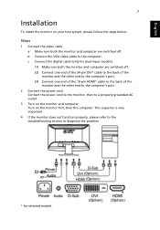
... to the troubleshooting section to diagnose the problem * for dual-input models). (1) Make sure both the monitor and computer are switched off. (2) Connect one end of the 24-pin DVI* cable to the back of the monitor and the other end to the computer's port. (3) Connect one end of the 19-pin HDMI...* cable to the back of the monitor and the other end to the computer's port. 2 Connect the power...
... to the troubleshooting section to diagnose the problem * for dual-input models). (1) Make sure both the monitor and computer are switched off. (2) Connect one end of the 24-pin DVI* cable to the back of the monitor and the other end to the computer's port. (3) Connect one end of the 19-pin HDMI...* cable to the back of the monitor and the other end to the computer's port. 2 Connect the power...

