Service Guide
Page 3
... cost of all necessary servicing, repair, and any language or computer language, in this manual is sold or licensed "as is a registered trademark of Emachine Incorporated. Alerts you to do specific actions relevant to change without the prior written permission of Intel Corporation. Copyright Copyright © 2008 by any damage that appear on screen. Emachine Incorporated makes no representations or warranties...
... cost of all necessary servicing, repair, and any language or computer language, in this manual is sold or licensed "as is a registered trademark of Emachine Incorporated. Alerts you to do specific actions relevant to change without the prior written permission of Intel Corporation. Copyright Copyright © 2008 by any damage that appear on screen. Emachine Incorporated makes no representations or warranties...
Service Guide
Page 4
... machines. This Service Guide provides you with all power cables and modem cables from the wall outlets before cleaning the system. ■ Unplug the system from that to order FRU parts for help. To better fit local market requirements and enhance product competitiveness, your regional Emachine office to which can radiate radio frequency energy and, if not installed and used in accordance with...
... machines. This Service Guide provides you with all power cables and modem cables from the wall outlets before cleaning the system. ■ Unplug the system from that to order FRU parts for help. To better fit local market requirements and enhance product competitiveness, your regional Emachine office to which can radiate radio frequency energy and, if not installed and used in accordance with...
Service Guide
Page 5
... protect it on the monitor cabinet. Special Notes On LCD Monitors The following symptoms are not blocked or covered. If you mount the monitor on a wall or shelf, uses a mounting kit approved by changing the image or turning off the Power Switch and then turn it from overheating, be operated only from damage due to the appliance. z The LCD screen has effective pixels of power source indicated on a bed, sofa...
... protect it on the monitor cabinet. Special Notes On LCD Monitors The following symptoms are not blocked or covered. If you mount the monitor on a wall or shelf, uses a mounting kit approved by changing the image or turning off the Power Switch and then turn it from overheating, be operated only from damage due to the appliance. z The LCD screen has effective pixels of power source indicated on a bed, sofa...
Service Guide
Page 6
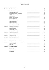
... Contents Chapter 1 Monitor Features Introduction Electrical Requirements LCD Monitor General Specification LCD Panel Specification Support Timing Monitor Block Diagram Main Board Diagram Software Flow chart Main Board Layout Cable Connections Adjusting the viewing angle Chapter 2 Operating Instructions External Controls Adjusting the picture Chapter 3 Machine Disassembly Chapter 4 Troubleshooting Chapter 5 Connector Information Chapter 6 FRU (Field Replacement Unit) List Exploded Diagram Part List Chapter 7 Schematic Diagram Main Board Power Board 7 7 8 9 10 14...
... Contents Chapter 1 Monitor Features Introduction Electrical Requirements LCD Monitor General Specification LCD Panel Specification Support Timing Monitor Block Diagram Main Board Diagram Software Flow chart Main Board Layout Cable Connections Adjusting the viewing angle Chapter 2 Operating Instructions External Controls Adjusting the picture Chapter 3 Machine Disassembly Chapter 4 Troubleshooting Chapter 5 Connector Information Chapter 6 FRU (Field Replacement Unit) List Exploded Diagram Part List Chapter 7 Schematic Diagram Main Board Power Board 7 7 8 9 10 14...
Service Guide
Page 7
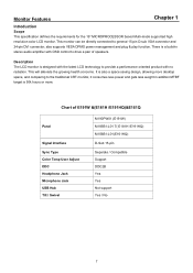
... specification defines the requirements for the 19" MICROPROCESSOR based Multi-mode supported high resolution color LCD monitor. This monitor can be directly connected to the traditional CRT monitor, it consumes less power and gets less weight in stereo audio amplifier with OSD control to provide a performance oriented product with the latest LCD technology to drive a pair of E191W &(E181H /E191HQ)&E161Q Panel Signal Interface Sync Type Color Temp User Adjust DDC Headphone Jack Microphone Jack USB...
... specification defines the requirements for the 19" MICROPROCESSOR based Multi-mode supported high resolution color LCD monitor. This monitor can be directly connected to the traditional CRT monitor, it consumes less power and gets less weight in stereo audio amplifier with OSD control to provide a performance oriented product with the latest LCD technology to drive a pair of E191W &(E181H /E191HQ)&E161Q Panel Signal Interface Sync Type Color Temp User Adjust DDC Headphone Jack Microphone Jack USB...
Service Guide
Page 8
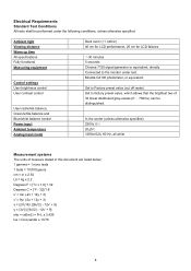
Electrical Requirements Standard Test Conditions All tests shall be performed under the following conditions, unless otherwise specified. Ambient light Viewing distance Warm up time All specifications Fully functional Measuring equipment Control settings User brightness control User contrast control User red/white balance, Green/white balance and Blue/white balance control Power input Ambient temperature Analog input mode : Dark room (
Electrical Requirements Standard Test Conditions All tests shall be performed under the following conditions, unless otherwise specified. Ambient light Viewing distance Warm up time All specifications Fully functional Measuring equipment Control settings User brightness control User contrast control User red/white balance, Green/white balance and Blue/white balance control Power input Ambient temperature Analog input mode : Dark room (
Service Guide
Page 10
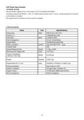
LCD Panel Specification 1.M19PW01(E191W) This specification applies to the 19 inch-wide clor TFT-LCD Module M19PW01. The display supports the WXGA+(1440(H)X 900(V)screen format and 16.7 colors。All input signals are 2 Channel LVDS interface comlatible。 This module does not contain an inverter card for backlight LCD Panel Model 10
LCD Panel Specification 1.M19PW01(E191W) This specification applies to the 19 inch-wide clor TFT-LCD Module M19PW01. The display supports the WXGA+(1440(H)X 900(V)screen format and 16.7 colors。All input signals are 2 Channel LVDS interface comlatible。 This module does not contain an inverter card for backlight LCD Panel Model 10
Service Guide
Page 11
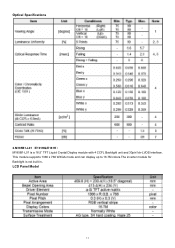
This module supports 1366 x 768 WXGA mode and can display up to 16.7M colors.The inverter module for Backlight is a 18.5" TFT Liquid Crystal Display module with 4 CCFL Backlight unit and 30pin1ch-LVDS interface. Optical Specifications 2.M185B1-L01(E191HQ/E181H) M185B1-L01 is not built in。 LCD Panel Model 11
This module supports 1366 x 768 WXGA mode and can display up to 16.7M colors.The inverter module for Backlight is a 18.5" TFT Liquid Crystal Display module with 4 CCFL Backlight unit and 30pin1ch-LVDS interface. Optical Specifications 2.M185B1-L01(E191HQ/E181H) M185B1-L01 is not built in。 LCD Panel Model 11
Service Guide
Page 12
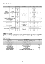
Optical Specifications 3. The inverter module for Backlight is a 15.6" TFT Liquid Crystal Display module with 2 CCFL Backlight unit and 30pin 1ch-LVDS interface. M156B1-L01 (E161HQ) M156B1-L01 is not built in. This module supports 1366 x 768 WXGA mode and can display up to 16.7M colors. LCD Panel Model 12
Optical Specifications 3. The inverter module for Backlight is a 15.6" TFT Liquid Crystal Display module with 2 CCFL Backlight unit and 30pin 1ch-LVDS interface. M156B1-L01 (E161HQ) M156B1-L01 is not built in. This module supports 1366 x 768 WXGA mode and can display up to 16.7M colors. LCD Panel Model 12
Service Guide
Page 16
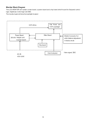
CCFL Drive. Flat Panel and CCFL backlight Power Board (Include: Adapter and Inverter board) AC-IN 100V-240V Main Board Key board RS232 Connector For white balance adjustment in factory mode Host Computer Video signal, DDC 16 Monitor Block Diagram The LCD MONITOR will drive the backlight of panel. The Inverter board will contain a main board, a power board and a key board which house the flat panel control logic, brightness control logic and DDC.
CCFL Drive. Flat Panel and CCFL backlight Power Board (Include: Adapter and Inverter board) AC-IN 100V-240V Main Board Key board RS232 Connector For white balance adjustment in factory mode Host Computer Video signal, DDC 16 Monitor Block Diagram The LCD MONITOR will drive the backlight of panel. The Inverter board will contain a main board, a power board and a key board which house the flat panel control logic, brightness control logic and DDC.
Service Guide
Page 19
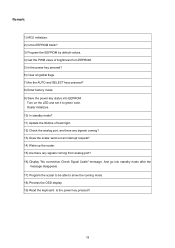
... default values. 4) Get the PWM value of back light. 12) Check the analog port, are there any signals coming? 13) Does the scalar send out an interrupt request? 14) Wake up the scalar. 15) Are there any signals coming mode. 18) Process the OSD display. 19) Read the keyboard. Scalar initializes. 10) In standby mode? 11) Update the lifetime of brightness from analog port? 16) Display "No connection Check Signal Cable...
... default values. 4) Get the PWM value of back light. 12) Check the analog port, are there any signals coming? 13) Does the scalar send out an interrupt request? 14) Wake up the scalar. 15) Are there any signals coming mode. 18) Process the OSD display. 19) Read the keyboard. Scalar initializes. 10) In standby mode? 11) Update the lifetime of brightness from analog port? 16) Display "No connection Check Signal Cable...
Service Guide
Page 23
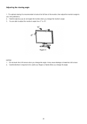
It may cause damage or break the LCD screen. 2、 Careful attention is recommended to look at the full face of the monitor, then adjust the monitor's angle to your own preference. 2、 Hold the stand so you do not topple the monitor when you change the monitor's angle. 3、 You are able to adjust the monitor's angle from -5° to catch your fingers or hands when you change the angle. 23 Adjusting the viewing angle 1、For optimal viewing it is required not to 15°. NOTES 1、 Do not touch the LCD screen when you change the angle.
It may cause damage or break the LCD screen. 2、 Careful attention is recommended to look at the full face of the monitor, then adjust the monitor's angle to your own preference. 2、 Hold the stand so you do not topple the monitor when you change the monitor's angle. 3、 You are able to adjust the monitor's angle from -5° to catch your fingers or hands when you change the angle. 23 Adjusting the viewing angle 1、For optimal viewing it is required not to 15°. NOTES 1、 Do not touch the LCD screen when you change the angle.
Service Guide
Page 24
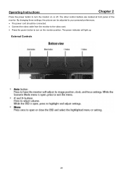
External Controls 24 The other control buttons are located at front panel of the monitor. By changing these settings, the picture can be adjusted to your personal preferences. • The power cord should be connected. • Connect the video cable from the monitor to the video card. • Press the power button to turn on or off. Operating Instructions Chapter 2 Press the power button to turn the monitor on the monitor position. The power indicator will light up.
External Controls 24 The other control buttons are located at front panel of the monitor. By changing these settings, the picture can be adjusted to your personal preferences. • The power cord should be connected. • Connect the video cable from the monitor to the video card. • Press the power button to turn on or off. Operating Instructions Chapter 2 Press the power button to turn the monitor on the monitor position. The power indicator will light up.
Service Guide
Page 27
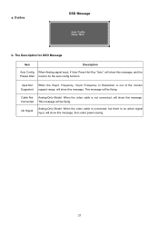
... Signal Analog-Only Model: When the video cable is connected, but there is not connected, will show this message. Cable Not Analog-Only Model: When the video cable is no active signal input, will show this message, and the Please Wait monitor do the auto config function. The Description for OSD Message Item Description Auto Config When Analog signal input, if User Press Hot-Key "Auto", will show this message, then enter power saving. 27 Connected...
... Signal Analog-Only Model: When the video cable is connected, but there is not connected, will show this message. Cable Not Analog-Only Model: When the video cable is no active signal input, will show this message, and the Please Wait monitor do the auto config function. The Description for OSD Message Item Description Auto Config When Analog signal input, if User Press Hot-Key "Auto", will show this message, then enter power saving. 27 Connected...
Service Guide
Page 28
... a key on type connector body, rated 10A, 250V, having standard CEE-22 female configuration. Please note that power supply cord needs to inform the host system of its display capabilities. It allows the monitor to use a cord set by reducing power consumption when there is no video input signal. This monitor will automatically switch to a "Screen Saver" feature except the display is a bi-directional data channel based on the level...
... a key on type connector body, rated 10A, 250V, having standard CEE-22 female configuration. Please note that power supply cord needs to inform the host system of its display capabilities. It allows the monitor to use a cord set by reducing power consumption when there is no video input signal. This monitor will automatically switch to a "Screen Saver" feature except the display is a bi-directional data channel based on the level...

Service Guide
Page 32
The monitor disassembly completely. (Fig 12) Fig 11 Fig 12 32 Remove the screws marked in red and the wire connect with power board to remove the boards. (Fig 10,11) Fig 10 6. 4.
The monitor disassembly completely. (Fig 12) Fig 11 Fig 12 32 Remove the screws marked in red and the wire connect with power board to remove the boards. (Fig 10,11) Fig 10 6. 4.
Service Guide
Page 35
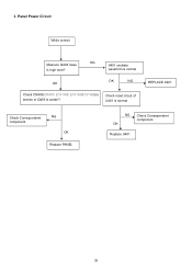
waveform is normal OK NG OK Check CN403(CN405: E191HQ/ E181H&E161HQ) is broken or Q405 is normal REPLACE X401 Check Correspondent component. Check reset circuit of U401 is solder? OK Replace U401 35 Panel Power Circuit White screen NG Measure Q404 base X401 oscillate is high level? NG OK Replace PANEL NG Check Correspondent component. 3.
waveform is normal OK NG OK Check CN403(CN405: E191HQ/ E181H&E161HQ) is broken or Q405 is normal REPLACE X401 Check Correspondent component. Check reset circuit of U401 is solder? OK Replace U401 35 Panel Power Circuit White screen NG Measure Q404 base X401 oscillate is high level? NG OK Replace PANEL NG Check Correspondent component. 3.
Service Guide
Page 40
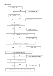
2.) No Backlight Check F801=12V NG OK Check ON/OFF signal NG OK Check IC801 PIN12=15V NG OK Check adapter and F801 Check Interface board or main board Change on/off circuit Check IC801 PIN5 have triangle wave NG OK Change IC801 Check IC801 PIN9/PIN10 PWM wave NG OK Check IC801 Check Q802,Q803 Drain wave NG OK Check Q801/Q804/Q811/Q812 Check the output of T801, T802 NG OK Change T801, T802 Check connecter & lamp, feedback and protect circuit 40
2.) No Backlight Check F801=12V NG OK Check ON/OFF signal NG OK Check IC801 PIN12=15V NG OK Check adapter and F801 Check Interface board or main board Change on/off circuit Check IC801 PIN5 have triangle wave NG OK Change IC801 Check IC801 PIN9/PIN10 PWM wave NG OK Check IC801 Check Q802,Q803 Drain wave NG OK Check Q801/Q804/Q811/Q812 Check the output of T801, T802 NG OK Change T801, T802 Check connecter & lamp, feedback and protect circuit 40
Service Guide
Page 42
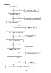
2.) No Backlight Check F801=12V NG OK Check ON/OFF signal NG OK Check IC801 PIN12=15V NG OK Check adapter and F801 Check Interface board or main board Change on/off circuit Check IC801 PIN5 have triangle wave NG OK Check IC801 PIN9/PIN10 PWM wave NG OK Change IC801 Check IC801 Check Q802 Drain wave NG OK Check Q801/Q804/Q811/Q812 Check the output of T801 NG OK Change T801 Check connecter & lamp, feedback and protect circuit 42
2.) No Backlight Check F801=12V NG OK Check ON/OFF signal NG OK Check IC801 PIN12=15V NG OK Check adapter and F801 Check Interface board or main board Change on/off circuit Check IC801 PIN5 have triangle wave NG OK Check IC801 PIN9/PIN10 PWM wave NG OK Change IC801 Check IC801 Check Q802 Drain wave NG OK Check Q801/Q804/Q811/Q812 Check the output of T801 NG OK Change T801 Check connecter & lamp, feedback and protect circuit 42
Service Guide
Page 43
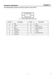
Pin Color Display Signal Cable (D-sub) Description Red Green Blue RS232 DDC-Return R-Ground G-Ground B-Ground Pin No. 9. 10. 11. 12. 13. 14. 15. Description +5V RS232 Monitor Ground DDC-Serial Data H-Sync V-Sync DDC-Serial Clock 43 43 Connector Information The following figure shows the connector locations on the monitor: Chapter 5 Pin No. 1. 2. 3. 4. 5. 6. 7. 8. 1 5 6 10 11 15 15 -
Pin Color Display Signal Cable (D-sub) Description Red Green Blue RS232 DDC-Return R-Ground G-Ground B-Ground Pin No. 9. 10. 11. 12. 13. 14. 15. Description +5V RS232 Monitor Ground DDC-Serial Data H-Sync V-Sync DDC-Serial Clock 43 43 Connector Information The following figure shows the connector locations on the monitor: Chapter 5 Pin No. 1. 2. 3. 4. 5. 6. 7. 8. 1 5 6 10 11 15 15 -


