Service Guide
Page 7
... 10 Using the Keyboard 11 Windows Keys 12 Hardware Specifications and Configurations 13 System Utilities 23 BIOS Setup Utility 23 Navigating the BIOS Utility 23 CMOS Setup Utility 24 Product Information 25 Standard CMOS Features 26 Advanced BIOS Features 27 Advanced Chipset Features 28 Integrated Peripherals 29 Power Management Features 30 PC Health 31 Frequency Voltage Control 32 BIOS Security Features 33 BIOS Flash Utilities 36 DOS Flash Utility 37 Win Flash Utility 38 Using DMI Tools 39 Machine Disassembly and Replacement 40 Disassembly...
... 10 Using the Keyboard 11 Windows Keys 12 Hardware Specifications and Configurations 13 System Utilities 23 BIOS Setup Utility 23 Navigating the BIOS Utility 23 CMOS Setup Utility 24 Product Information 25 Standard CMOS Features 26 Advanced BIOS Features 27 Advanced Chipset Features 28 Integrated Peripherals 29 Power Management Features 30 PC Health 31 Frequency Voltage Control 32 BIOS Security Features 33 BIOS Flash Utilities 36 DOS Flash Utility 37 Win Flash Utility 38 Using DMI Tools 39 Machine Disassembly and Replacement 40 Disassembly...

Service Guide
Page 8
...Eject Board 134 Replacing the Audio Board 135 Connect the Card Reader Board 136 Replacing the Touchscreen Board 137 Replacing the Power Supply 139 Replacing the HDD 140 Replacing the Mainboard Shielding 142 Replacing the Hinge 146 Replacing the Rear Cover 147 Replacing the Rear Covers 149 Replacing the RAM 151 Replacing the Rear Covers 152 Troubleshooting 154 Common Problems 154 ODD Failure 155 Wireless Failure 158 Camera Failure 159 Speaker Failure 160 LCD Failure 162 General Troubleshooting Issues 164 Intermittent Problems 167 Undetermined Problems 167 POST Codes 168...
...Eject Board 134 Replacing the Audio Board 135 Connect the Card Reader Board 136 Replacing the Touchscreen Board 137 Replacing the Power Supply 139 Replacing the HDD 140 Replacing the Mainboard Shielding 142 Replacing the Hinge 146 Replacing the Rear Cover 147 Replacing the Rear Covers 149 Replacing the RAM 151 Replacing the Rear Covers 152 Troubleshooting 154 Common Problems 154 ODD Failure 155 Wireless Failure 158 Camera Failure 159 Speaker Failure 160 LCD Failure 162 General Troubleshooting Issues 164 Intermittent Problems 167 Undetermined Problems 167 POST Codes 168...
Service Guide
Page 18
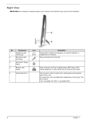
... listen to audio CDs, install games and programs, watch DVDs, and store large files onto recordable discs (depending on drive type). Use this illustration. This drive may vary from a digital camera, MP3 player, PDA, cellular telephone, or other device into this jack. No. 1 2 Component Headphone jack (white plug) Microphone jack (pink plug) 3 Illumination Toggle Switch 4 Memory card reader 5 Optical Disk Drive Icon Description Plug powered, analog front speakers, an external amplifier, or...
... listen to audio CDs, install games and programs, watch DVDs, and store large files onto recordable discs (depending on drive type). Use this illustration. This drive may vary from a digital camera, MP3 player, PDA, cellular telephone, or other device into this jack. No. 1 2 Component Headphone jack (white plug) Microphone jack (pink plug) 3 Illumination Toggle Switch 4 Memory card reader 5 Optical Disk Drive Icon Description Plug powered, analog front speakers, an external amplifier, or...
Service Guide
Page 20
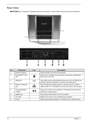
... cable or a device (such as a USB printer, scanner, camera, keyboard, or mouse) into this illustration. Plug external hard drives into this connector. Component 1 Power connector 2 Kensington™ lock slot 3 USB ports 4 Ethernet (network) jack 5 Line-out/Speaker- out jack 6 eSATA port 7 TV Tuner 8 IR port Icon Description Plug the power cord into this connector. Plug an line output to the system. Rear View IMPORTANT:Your computer's hardware options, port locations, and indicators may vary from this jack for a broadband Internet connection...
... cable or a device (such as a USB printer, scanner, camera, keyboard, or mouse) into this illustration. Plug external hard drives into this connector. Component 1 Power connector 2 Kensington™ lock slot 3 USB ports 4 Ethernet (network) jack 5 Line-out/Speaker- out jack 6 eSATA port 7 TV Tuner 8 IR port Icon Description Plug the power cord into this connector. Plug an line output to the system. Rear View IMPORTANT:Your computer's hardware options, port locations, and indicators may vary from this jack for a broadband Internet connection...
Service Guide
Page 24
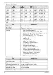
....CI5 KC.75001.CI5 KC.86001.CI7 KC.87001.CI7 Specification American Megatrends 3.0 16Mbits, 8 pin SOIC package • PC/AT Compatible System BIOS. • ACPI 3.0 Compliance/Support, S0, S1, S3, S4, S5. • Boot Block Recovery mode from CD-ROM/USB FDD/USB CD- ROM/USB-DVD ROM/USB Disk-On-Key • Security Setting (Password on boot or Setup Menu). • BIOS update in 2 512/1024/2048MB (1 bank or 2 bank) 8192MB (4096MB+4096MB...
....CI5 KC.75001.CI5 KC.86001.CI7 KC.87001.CI7 Specification American Megatrends 3.0 16Mbits, 8 pin SOIC package • PC/AT Compatible System BIOS. • ACPI 3.0 Compliance/Support, S0, S1, S3, S4, S5. • Boot Block Recovery mode from CD-ROM/USB FDD/USB CD- ROM/USB-DVD ROM/USB Disk-On-Key • Security Setting (Password on boot or Setup Menu). • BIOS update in 2 512/1024/2048MB (1 bank or 2 bank) 8192MB (4096MB+4096MB...
Service Guide
Page 33
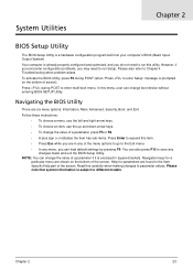
... to enter multi-boot menu. Follow these instructions: • To choose a menu, use the left and right arrow keys. • To choose an item, use the up and down arrow keys. • To change the value of screen). NOTE: You can change boot device without entering BIOS SETUP Utility. System Utilities Chapter 2 BIOS Setup Utility The BIOS Setup Utility is subject to different models. Press during POST (when "Press to parameter values. Read this menu, user can load default settings...
... to enter multi-boot menu. Follow these instructions: • To choose a menu, use the left and right arrow keys. • To choose an item, use the up and down arrow keys. • To change the value of screen). NOTE: You can change boot device without entering BIOS SETUP Utility. System Utilities Chapter 2 BIOS Setup Utility The BIOS Setup Utility is subject to different models. Press during POST (when "Press to parameter values. Read this menu, user can load default settings...
Service Guide
Page 37
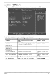
... time needed to skip certain steps while booting. Boot Num-Lock USB Beep Message Turns Num-Lock on or off on boot up. Allows a beep during booting. CMOS Setup Utility - Copyright (C) 1985-2010, American Megatrends Inc. Format/Option Enabled or Disabled Enabled or Disabled Press Enter to set the order priority Press Enter to set the boot driver priority. Parameter Quick Boot Quiet Boot 1st Boot Device 2nd Boot Device 3rd Boot Device 4th Boot Device Hard Disk Drive Priority Description Allows BIOS to boot the system. Optical Disk Driver Priority Enter...
... time needed to skip certain steps while booting. Boot Num-Lock USB Beep Message Turns Num-Lock on or off on boot up. Allows a beep during booting. CMOS Setup Utility - Copyright (C) 1985-2010, American Megatrends Inc. Format/Option Enabled or Disabled Enabled or Disabled Press Enter to set the order priority Press Enter to set the boot driver priority. Parameter Quick Boot Quiet Boot 1st Boot Device 2nd Boot Device 3rd Boot Device 4th Boot Device Hard Disk Drive Priority Description Allows BIOS to boot the system. Optical Disk Driver Priority Enter...
Service Guide
Page 43
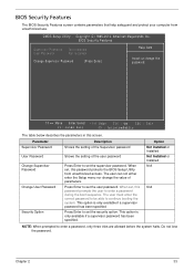
...unauthorized access. Option Not Installed or Installed Not Installed or Installed N/A N/A NOTE: When prompted to continue booting the system. This option is only available if a supervisor password has been specified Press Enter to set , this screen. BIOS Security Features Supervisor Password :Not Installed User Password :Not Installed Change Supervisor Password [Press Enter] Help Item Install or change the value of the user password Press Enter to enter a password during the boot sequence. When set the user password. Parameter Supervisor Password User Password Change...
...unauthorized access. Option Not Installed or Installed Not Installed or Installed N/A N/A NOTE: When prompted to continue booting the system. This option is only available if a supervisor password has been specified Press Enter to set , this screen. BIOS Security Features Supervisor Password :Not Installed User Password :Not Installed Change Supervisor Password [Press Enter] Help Item Install or change the value of the user password Press Enter to enter a password during the boot sequence. When set the user password. Parameter Supervisor Password User Password Change...
Service Guide
Page 44
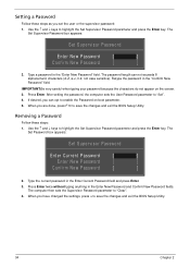
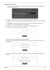
... changes and exit the BIOS Setup Utility. 34 Chapter 2 When you have changed the settings, press u to enable the Password on the screen. 3. Retype the password in the Enter New Password and Confirm New Password fields. Type a password in the Enter Current Password field and press Enter. 3. Removing a Password Follow these steps as you can not exceeds 8 alphanumeric characters (A-Z, a-z, 0-9, not case sensitive). Use the and keys to "Set". 4. IMPORTANT:Be very careful when typing your password...
... changes and exit the BIOS Setup Utility. 34 Chapter 2 When you have changed the settings, press u to enable the Password on the screen. 3. Retype the password in the Enter New Password and Confirm New Password fields. Type a password in the Enter Current Password field and press Enter. 3. Removing a Password Follow these steps as you can not exceeds 8 alphanumeric characters (A-Z, a-z, 0-9, not case sensitive). Use the and keys to "Set". 4. IMPORTANT:Be very careful when typing your password...
Service Guide
Page 45
... exit the BIOS Setup Utility. Setup Notice Changes have been saved. [Continue] The password setting is OK, the screen will display the following . Setup Warning Passwords do not match, the screen will display as following message. Setup Warning Invalid Password. [Continue] If the new password and confirm new password strings do not match. Type a password in the Enter Current Password field and press Enter. 3. The Set Password box appears. After setting the password, the computer sets the User Password parameter to...
... exit the BIOS Setup Utility. Setup Notice Changes have been saved. [Continue] The password setting is OK, the screen will display the following . Setup Warning Passwords do not match, the screen will display as following message. Setup Warning Invalid Password. [Continue] If the new password and confirm new password strings do not match. Type a password in the Enter Current Password field and press Enter. 3. The Set Password box appears. After setting the password, the computer sets the User Password parameter to...
Service Guide
Page 47
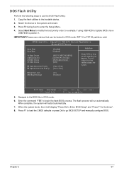
... Update BIOS, move USB HDD to use a device that can be booted in DOS mode. 6. IMPORTANT:Please use the DOS Flash Utility: 1. Chapter 2 37 When complete, the system will reduce the time needed to the BIOS file in DOS mode (FAT 16 or FAT 32 partitions only) CMOS Setup Utility - DOS Flash Utility Perform the following steps to position 1. This will restart automatically. 7. Copy the flash utilities to enter the Setup Menu. 4. Bootup Num-Lock USB Beep...
... Update BIOS, move USB HDD to use a device that can be booted in DOS mode. 6. IMPORTANT:Please use the DOS Flash Utility: 1. Chapter 2 37 When complete, the system will reduce the time needed to the BIOS file in DOS mode (FAT 16 or FAT 32 partitions only) CMOS Setup Utility - DOS Flash Utility Perform the following steps to position 1. This will restart automatically. 7. Copy the flash utilities to enter the Setup Menu. 4. Bootup Num-Lock USB Beep...
Service Guide
Page 164
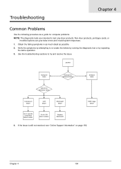
START Hardware Issue Hardware or Software failure? Obtain the failing symptoms in as much detail as a guide for computer problems. NOTE: The diagnostic tests are intended to re-create the failure by running the diagnostic test or by repeating the same operation. 3. Software Issue Determine Hardware failure Component failure LCD failure Mainboard failure HDD Image failure Go to specific component failure section Go to try and resolve the issue. Use the troubleshooting sections to LCD failure section Replace Mainboard 4. Chapter...
START Hardware Issue Hardware or Software failure? Obtain the failing symptoms in as much detail as a guide for computer problems. NOTE: The diagnostic tests are intended to re-create the failure by running the diagnostic test or by repeating the same operation. 3. Software Issue Determine Hardware failure Component failure LCD failure Mainboard failure HDD Image failure Go to specific component failure section Go to try and resolve the issue. Use the troubleshooting sections to LCD failure section Replace Mainboard 4. Chapter...
Service Guide
Page 166
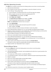
...; Control Panel Hardware and Sound AutoPlay. Click Properties. b. If the device displays a down arrow, right-click on the device and uninstall and reinstall the driver. e. Check that the media is the factory default. Right-click DVD drive and click Properties, then click the DVD Region tab. d. Check that the Regional Code is moved to correct the problem. 1. Ensure that there are not running low: a. If using...
...; Control Panel Hardware and Sound AutoPlay. Click Properties. b. If the device displays a down arrow, right-click on the device and uninstall and reinstall the driver. e. Check that the media is the factory default. Right-click DVD drive and click Properties, then click the DVD Region tab. d. Check that the Regional Code is moved to correct the problem. 1. Ensure that there are not running low: a. If using...
Service Guide
Page 170
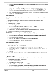
... updated recently. 4. Roll back the audio driver to Start Control Panel Hardware and Sound Sound. Ensure that other audio applications are set mid range: a. Remove and recently installed hardware or software. Click Mixer to Start Control Panel System and Maintenance System Device Manager. Remove and reinstall the audio driver. 5. Chapter 4 160 Ensure that the volume is listed under Other Devices. 3. Select Speakers and click Configure to correct the problem. 1. Speaker Failure If the internal speaker fails, use...
... updated recently. 4. Roll back the audio driver to Start Control Panel Hardware and Sound Sound. Ensure that other audio applications are set mid range: a. Remove and recently installed hardware or software. Click Mixer to Start Control Panel System and Maintenance System Device Manager. Remove and reinstall the audio driver. 5. Chapter 4 160 Ensure that the volume is listed under Other Devices. 3. Select Speakers and click Configure to correct the problem. 1. Speaker Failure If the internal speaker fails, use...
Service Guide
Page 173
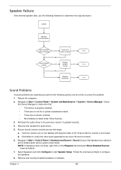
.... • There are no device conflicts. • No hardware is correctly configured: a. Run the Windows Memory Diagnostic from the operating system DVD and follow the onscreen prompts. 11. If display size is only abnormal in an application, check the view settings and control/mouse wheel zoom feature in the same locations on the screen), the LCD is faulty and should be replaced. Click and drag the...
.... • There are no device conflicts. • No hardware is correctly configured: a. Run the Windows Memory Diagnostic from the operating system DVD and follow the onscreen prompts. 11. If display size is only abnormal in an application, check the view settings and control/mouse wheel zoom feature in the same locations on the screen), the LCD is faulty and should be replaced. Click and drag the...
Service Guide
Page 174
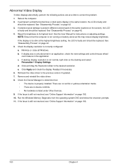
..., see "Online Support Information" on page 192. Test the microphone hardware: a. If the Issue is virus free. 3. Random Loss of BIOS Settings If the computer is enabled. Replace the Motherboard. 6. Right-click on the Recording tab and select Show Disabled Devices (clear by default). 3. Select Set up -to-date software to the failure point. 6. Plug the computer directly into a known good electrical outlet. 4. Remove any extension cables between the...
..., see "Online Support Information" on page 192. Test the microphone hardware: a. If the Issue is virus free. 3. Random Loss of BIOS Settings If the computer is enabled. Replace the Motherboard. 6. Right-click on the Recording tab and select Show Disabled Devices (clear by default). 3. Select Set up -to-date software to the failure point. 6. Plug the computer directly into a known good electrical outlet. 4. Remove any extension cables between the...
Service Guide
Page 175
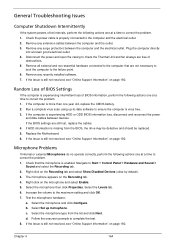
.... Run the Windows Disk Defragmenter. Restore system and file settings from a known good date using up-to-date software to ensure the computer is set correctly. 7. See "Disassembly Process" on the Boot menu. 6. See the mouse user manual. 3. Restart the computer. 6. Remove any key to start to the operating system DVD. Restore system and file settings from a command prompt. e. Select Startup Repair. Try an alternative mouse. 2. When prompted, press any recently added software and reboot. 8. h. External Mouse Failure If an external Mouse...
.... Run the Windows Disk Defragmenter. Restore system and file settings from a known good date using up-to-date software to ensure the computer is set correctly. 7. See "Disassembly Process" on the Boot menu. 6. See the mouse user manual. 3. Restart the computer. 6. Remove any key to start to the operating system DVD. Restore system and file settings from a command prompt. e. Select Startup Repair. Try an alternative mouse. 2. When prompted, press any recently added software and reboot. 8. h. External Mouse Failure If an external Mouse...
Service Guide
Page 177
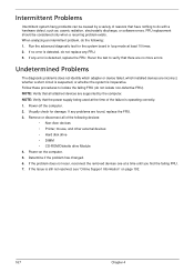
... a recurring problem exists. When analyzing an intermittent problem, do not replace any FRU. 3. NOTE: Verify that have nothing to isolate the failing FRU (do with a hardware defect, such as: cosmic radiation, electrostatic discharge, or software errors. If any error is detected, do the following devices: • Non-Acer devices • Printer, mouse, and other external devices • Hard disk drive • DIMM • CD-ROM/Diskette drive Module 4.
... a recurring problem exists. When analyzing an intermittent problem, do not replace any FRU. 3. NOTE: Verify that have nothing to isolate the failing FRU (do with a hardware defect, such as: cosmic radiation, electrostatic discharge, or software errors. If any error is detected, do the following devices: • Non-Acer devices • Printer, mouse, and other external devices • Hard disk drive • DIMM • CD-ROM/Diskette drive Module 4.
Service Guide
Page 179
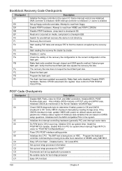
... the recovery file configuration to F000 ROM at F000:FFF0h. Detect proper flash part. Make flash write disabled. Restore CPUID value back into register. Give control to the current configuration of KB/MS using AMI KB-5. Also initialize BIOS modules on default values and clear passwords. Check CMOS diagnostic byte to read from floppy. If the CMOS checksum is being done on media. Program the keyboard controller command byte is bad, update CMOS with power...
... the recovery file configuration to F000 ROM at F000:FFF0h. Detect proper flash part. Make flash write disabled. Restore CPUID value back into register. Give control to the current configuration of KB/MS using AMI KB-5. Also initialize BIOS modules on default values and clear passwords. Check CMOS diagnostic byte to read from floppy. If the CMOS checksum is being done on media. Program the keyboard controller command byte is bad, update CMOS with power...
Service Guide
Page 180
... devices controlled by invoking all the output devices. Initializes the silent boot module. Execute BIOS setup if needed . Detects the presence of document for all available language, BIOS logo, and Silent logo modules. Initializes different devices through DIM. Give control to limit memory test. Detect different devices (Parallel ports, serial ports, and coprocessor in memory test. Updates CMOS memory size from base memory. Enable/Disable NMI as selected Initialization of system management interrupt by BIOS and option ROMs...
... devices controlled by invoking all the output devices. Initializes the silent boot module. Execute BIOS setup if needed . Detects the presence of document for all available language, BIOS logo, and Silent logo modules. Initializes different devices through DIM. Give control to limit memory test. Detect different devices (Parallel ports, serial ports, and coprocessor in memory test. Updates CMOS memory size from base memory. Enable/Disable NMI as selected Initialization of system management interrupt by BIOS and option ROMs...


