
Service Guide
Page 7
... Unit Disassembly 27 Removing the Side Panel 29 Removing the Front Bezel 30 Removing the Heatsink Fan Assembly 32 Removing the Processor 34 Removing the Optical Drive 36 Removing the Hard Disk Drive 39 Removing the Power Supply 40 Removing the Memory Modules 42 Removing an Expansion Card 43 Removing the Front I/O and Card Reader Boards 46 Removing the Mainboard 49 Removing the Top Bezel 51 System Troubleshooting 53 Hardware Diagnostic Procedure 53 System Check Procedures 54 Power System Check 54 System External...
... Unit Disassembly 27 Removing the Side Panel 29 Removing the Front Bezel 30 Removing the Heatsink Fan Assembly 32 Removing the Processor 34 Removing the Optical Drive 36 Removing the Hard Disk Drive 39 Removing the Power Supply 40 Removing the Memory Modules 42 Removing an Expansion Card 43 Removing the Front I/O and Card Reader Boards 46 Removing the Mainboard 49 Removing the Top Bezel 51 System Troubleshooting 53 Hardware Diagnostic Procedure 53 System Check Procedures 54 Power System Check 54 System External...
Service Guide
Page 9
... or dual-channel memory mode Maximum of the system depends on the model purchased. The exact configuration of 8GB supported Media storage Super-Multi DVD drive BD Combo, BD-ROM, BD-RW drive SATA hard disk drive Serial ATA controller Embedded SATA controllers Two SATA ports Audio Realtek ALC888S-VC HD Audio Codec 7.1 Three audio jacks Networking Intel PCI-E Gbe LAN controller PHY One Gigabit Ethernet LAN port (RJ-45) PCI I/O PCI...
... or dual-channel memory mode Maximum of the system depends on the model purchased. The exact configuration of 8GB supported Media storage Super-Multi DVD drive BD Combo, BD-ROM, BD-RW drive SATA hard disk drive Serial ATA controller Embedded SATA controllers Two SATA ports Audio Realtek ALC888S-VC HD Audio Codec 7.1 Three audio jacks Networking Intel PCI-E Gbe LAN controller PHY One Gigabit Ethernet LAN port (RJ-45) PCI I/O PCI...
Service Guide
Page 10
...-Picture Card™, Memory Stick™, Memory Stick PRO™ Rear PS/2 keyboard port PS/2 mouse port Three audio jacks HDMI port Six USB 2.0 ports Gigabit LAN port VGA/monitor port Operating system and software Operating system Windows 7 Home Premium x64 Windows 7 Home Premium X86 Windows 7 Home Basic X86, FreeDOS Linux LL95 Applications Acer eRecovery Management Acrobat Reader Acrobat Flash...
...-Picture Card™, Memory Stick™, Memory Stick PRO™ Rear PS/2 keyboard port PS/2 mouse port Three audio jacks HDMI port Six USB 2.0 ports Gigabit LAN port VGA/monitor port Operating system and software Operating system Windows 7 Home Premium x64 Windows 7 Home Premium X86 Windows 7 Home Basic X86, FreeDOS Linux LL95 Applications Acer eRecovery Management Acrobat Reader Acrobat Flash...

Service Guide
Page 22
... display error beeps or messages during USB device enumeration. On Off Enables or disables BIOS to access the Network Device Priority submenu and specify the boot sequence from the available devices. When disabled, the diagnostic screen displays during startup. This will decrease the time needed to boot the system. :Move Enter:Select F1:General Help +/-/:Value F10:Save ESC:Exit F9:Optimized Defaults Parameter Quick Boot Quiet Boot 1st/2nd/3rd/4th Boot Device Hard Disk Drive Priority Optical Disk Drive Priority Removable Device...
... display error beeps or messages during USB device enumeration. On Off Enables or disables BIOS to access the Network Device Priority submenu and specify the boot sequence from the available devices. When disabled, the diagnostic screen displays during startup. This will decrease the time needed to boot the system. :Move Enter:Select F1:General Help +/-/:Value F10:Save ESC:Exit F9:Optimized Defaults Parameter Quick Boot Quiet Boot 1st/2nd/3rd/4th Boot Device Hard Disk Drive Priority Optical Disk Drive Priority Removable Device...
Service Guide
Page 28
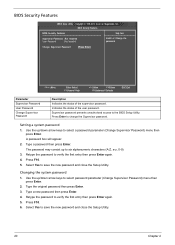
... password may consist up /down arrow keys to save the new password and close the Setup Utility. Type the original password then press Enter. 3. Retype the password to the BIOS Setup Utility. Change Supervisor Password [Press Enter] :Move Enter:Select F1:General Help +/-/:Value F10:Save F9:Optimized Defaults ESC:Exit Parameter Supervisor Password User Password Change Supervisor Password Description Indicates the status of the user password. BIOS Security Features CMOS Setup Utility - Select Yes to select a password parameter (Change Supervisor Password) menu...
... password may consist up /down arrow keys to save the new password and close the Setup Utility. Type the original password then press Enter. 3. Retype the password to the BIOS Setup Utility. Change Supervisor Password [Press Enter] :Move Enter:Select F1:General Help +/-/:Value F10:Save F9:Optimized Defaults ESC:Exit Parameter Supervisor Password User Password Change Supervisor Password Description Indicates the status of the user password. BIOS Security Features CMOS Setup Utility - Select Yes to select a password parameter (Change Supervisor Password) menu...
Service Guide
Page 35
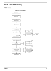
Main Unit Disassembly X3950 model MAIN UNIT DISASSEMBLY MAIN UNIT Ax2 SIDE PANEL FRONT BEZEL HEATSINK FAN ASSEMBLY PROCESSOR Cx2 HDD-ODD BRACKET Ax3, Bx1 POWER SUPPLY MEMORY MODULES PCI CARD Bx1 FRONT I/O AND CARD READER BOARD BRACKET Bx6 MAINBOARD Bx2 OPTICAL DISK DRIVE Dx4 HDD MODULE HDD Ax1 TV TUNER CARD or NETWORK CARD or GRAPHICS CARD Bx2 FRONT I/O BOARD Bx2 CARD READER BOARD Chapter 3 27
Main Unit Disassembly X3950 model MAIN UNIT DISASSEMBLY MAIN UNIT Ax2 SIDE PANEL FRONT BEZEL HEATSINK FAN ASSEMBLY PROCESSOR Cx2 HDD-ODD BRACKET Ax3, Bx1 POWER SUPPLY MEMORY MODULES PCI CARD Bx1 FRONT I/O AND CARD READER BOARD BRACKET Bx6 MAINBOARD Bx2 OPTICAL DISK DRIVE Dx4 HDD MODULE HDD Ax1 TV TUNER CARD or NETWORK CARD or GRAPHICS CARD Bx2 FRONT I/O BOARD Bx2 CARD READER BOARD Chapter 3 27
Service Guide
Page 36
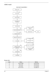
X5950 model MAIN UNIT DISASSEMBLY MAIN UNIT Ax2 SIDE PANEL FRONT BEZEL HEATSINK FAN ASSEMBLY PROCESSOR Cx2 HDD-ODD BRACKET Ax3, Bx1 POWER SUPPLY MEMORY MODULES PCI CARD Bx1 FRONT I/O AND CARD READER BOARD BRACKET Bx6 MAINBOARD TOP BEZEL Bx2 OPTICAL DISK DRIVE Dx4 HDD MODULE HDD Ax1 TV TUNER CARD or NETWORK CARD or GRAPHICS CARD Bx2 FRONT I/O BOARD Bx2 CARD READER BOARD Screw List Code A B C D 28 Screw #6-32 L5 BZN #6-32 L6 NI M3xL5 BZN #6-32*3/16 NI Part No. 86.00J07.B60 86.00J44.C60 86.1A324.5R0 86.5A5B6.012 Chapter 3
X5950 model MAIN UNIT DISASSEMBLY MAIN UNIT Ax2 SIDE PANEL FRONT BEZEL HEATSINK FAN ASSEMBLY PROCESSOR Cx2 HDD-ODD BRACKET Ax3, Bx1 POWER SUPPLY MEMORY MODULES PCI CARD Bx1 FRONT I/O AND CARD READER BOARD BRACKET Bx6 MAINBOARD TOP BEZEL Bx2 OPTICAL DISK DRIVE Dx4 HDD MODULE HDD Ax1 TV TUNER CARD or NETWORK CARD or GRAPHICS CARD Bx2 FRONT I/O BOARD Bx2 CARD READER BOARD Screw List Code A B C D 28 Screw #6-32 L5 BZN #6-32 L6 NI M3xL5 BZN #6-32*3/16 NI Part No. 86.00J07.B60 86.00J44.C60 86.1A324.5R0 86.5A5B6.012 Chapter 3
Service Guide
Page 63
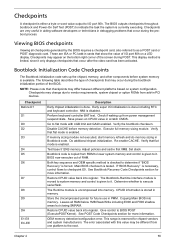
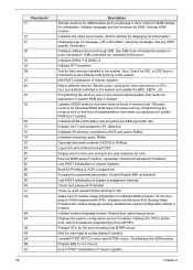
... memory detection. If memory sizing module not executed, start memory refresh and do memory sizing in PCI devices. Test base 512KB memory. Bootblock code is enabled. Restore CPUID value back into memory. The BIOS outputs checkpoints throughout bootblock and Power-On Self Test (POST) to indicate the task the system is necessary, control flows to the next. These are very useful in aiding software developers or technicians in scratch CMOS...
... memory detection. If memory sizing module not executed, start memory refresh and do memory sizing in PCI devices. Test base 512KB memory. Bootblock code is enabled. Restore CPUID value back into memory. The BIOS outputs checkpoints throughout bootblock and Power-On Self Test (POST) to indicate the task the system is necessary, control flows to the next. These are very useful in aiding software developers or technicians in scratch CMOS...
Service Guide
Page 65
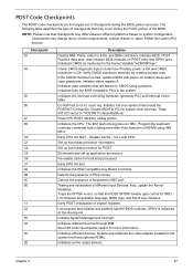
... POST code checkpoints are based on system configuration. Initialized CMOS as system timer.Install the POSTINT1Ch handler. Traps INT1Ch vector to determine if battery power is OK and CMOS checksum is initialized at this checkpoint. Testing and initialization of the BIOS. Uncompress all the output devices. GPNV is OK. Detects and initializes the video adapter installed in the system Initializes the interrupt controlling hardware (generally...
... POST code checkpoints are based on system configuration. Initialized CMOS as system timer.Install the POSTINT1Ch handler. Traps INT1Ch vector to determine if battery power is OK and CMOS checksum is initialized at this checkpoint. Testing and initialization of the BIOS. Uncompress all the output devices. GPNV is OK. Detects and initializes the video adapter installed in the system Initializes the interrupt controlling hardware (generally...
Service Guide
Page 66
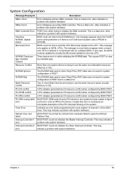
... OEM specific information. Initializes the Microsoft IRQ Routing Table. Displays the system configuration screen if enabled. Uninstall POST INT1Ch vector and INT09h vector. Chapter 4 Initializes the silent boot module. Wait for total memory installed in CPU, ... Deinitializes the ADM module. Display boot option popup menu. Displaying sign-on message, CPU information, setup key message, and any kind of implementation that needs an adjustment in system RAM size if needed . Updates CMOS memory size...
... OEM specific information. Initializes the Microsoft IRQ Routing Table. Displays the system configuration screen if enabled. Uninstall POST INT1Ch vector and INT09h vector. Chapter 4 Initializes the silent boot module. Wait for total memory installed in CPU, ... Deinitializes the ADM module. Display boot option popup menu. Displaying sign-on message, CPU information, setup key message, and any kind of implementation that needs an adjustment in system RAM size if needed . Updates CMOS memory size...
Service Guide
Page 71
... a problem with system hardware. Chapter 4 63 Error initializing secondary DMA controller. The NVRAM data used for the new CPU. A PCI adapter generated an I /O). This is no FLASH part (System uses a PROM or EPROM). The NVRAM data used to store Plug'n'Play (PnP) data was not used for system configuration in POST due to store Plug'n'Play (PnP) data was not used to a data error. Usually this case, the BIOS must be updated...
... a problem with system hardware. Chapter 4 63 Error initializing secondary DMA controller. The NVRAM data used for the new CPU. A PCI adapter generated an I /O). This is no FLASH part (System uses a PROM or EPROM). The NVRAM data used to store Plug'n'Play (PnP) data was not used for system configuration in POST due to store Plug'n'Play (PnP) data was not used to a data error. Usually this case, the BIOS must be updated...
Service Guide
Page 72
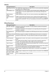
... Setup. CMOS contents failed the Checksum check. PS2 Keyboard support is enabled in the AMIBIOS8 ROM. User needs to unlock the keyboard to malfunction. The password entered does not match the password set in initializing legacy Floppy Controller. 64 Chapter 4 This condition may indicate a problem with system hardware. CMOS Message Displayed CMOS Date/Time Not Set CMOS Battery Low CMOS Settings Wrong CMOS Checksum Bad Description The CMOS Date and/or Time are invalid. Error code = 004Ah Unknown BIOS error. A reset...
... Setup. CMOS contents failed the Checksum check. PS2 Keyboard support is enabled in the AMIBIOS8 ROM. User needs to unlock the keyboard to malfunction. The password entered does not match the password set in initializing legacy Floppy Controller. 64 Chapter 4 This condition may indicate a problem with system hardware. CMOS Message Displayed CMOS Date/Time Not Set CMOS Battery Low CMOS Settings Wrong CMOS Checksum Bad Description The CMOS Date and/or Time are invalid. Error code = 004Ah Unknown BIOS error. A reset...
Service Guide
Page 75
... should be +12Vdc. Processor test failed. Action/FRU Memory module Mainboard Insert the memory modules in the DIMM sockets properly, then reboot the system. Memory module Mainboard Enter BIOS Setup and load default settings.In Windows Systems, check settings in Power Management Property of Control Panel. Reload software from Recovery CD. Diskette/IDE drive connection/cables Diskette/IDE disk drives See "Undetermined Problems". Mainboard...
... should be +12Vdc. Processor test failed. Action/FRU Memory module Mainboard Insert the memory modules in the DIMM sockets properly, then reboot the system. Memory module Mainboard Enter BIOS Setup and load default settings.In Windows Systems, check settings in Power Management Property of Control Panel. Reload software from Recovery CD. Diskette/IDE drive connection/cables Diskette/IDE disk drives See "Undetermined Problems". Mainboard...
Service Guide
Page 76
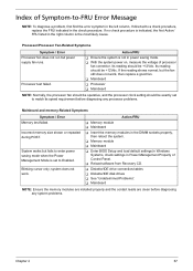
... diskette drive problems.(If only one drive is installed, please make sure the drive is connected to master connector or the drive is unable to master.) 68 Chapter 4 Action/FRU Ensure the diskette drive is configured correctly in BIOS Setup and its read /write error. Diskette drive LED fails to light, and the drive is set to None in the Disk Drives of BIOS Setup. Diskette drive power Diskette drive connection/cable Diskette drive ...
... diskette drive problems.(If only one drive is installed, please make sure the drive is connected to master connector or the drive is unable to master.) 68 Chapter 4 Action/FRU Ensure the diskette drive is configured correctly in BIOS Setup and its read /write error. Diskette drive LED fails to light, and the drive is set to None in the Disk Drives of BIOS Setup. Diskette drive power Diskette drive connection/cable Diskette drive ...
Service Guide
Page 77
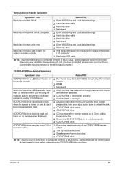
...; Enter BIOS Setup and Load default settings Hard disk drive cable Hard disk drive Mainboard Hard disk drive has write error. Enter BIOS Setup and Load default settings Hard disk drive Hard disk drive LED fails to light, but system operates normally. With the system power on, measure the voltage of the CD/DVD-ROM has an output. Turn up the sound volume. Speaker power/connection/cable. CD/DVD-ROM drive. Check with a known good disc. Ensure the CD/DVD-ROM driver is damaged. CD/DVD-ROM drive can...
...; Enter BIOS Setup and Load default settings Hard disk drive cable Hard disk drive Mainboard Hard disk drive has write error. Enter BIOS Setup and Load default settings Hard disk drive Hard disk drive LED fails to light, but system operates normally. With the system power on, measure the voltage of the CD/DVD-ROM has an output. Turn up the sound volume. Speaker power/connection/cable. CD/DVD-ROM drive. Check with a known good disc. Ensure the CD/DVD-ROM driver is damaged. CD/DVD-ROM drive can...
Service Guide
Page 78
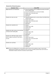
...; Remove all non-factory-installed cards. Load default settings (if screen is inaccurate. For the PCI modem, make sure Power on By Ring in cable from modem adapter card invokes but has no sound comes from modem cannot be produced, but system sound feature works normally.) Video and Monitor-Related Symptoms Symptom / Error Video memory test failed.Video adapter failed. Data/fax modem software program invokes Ensure the modem card is set correctly. RTC battery...
...; Remove all non-factory-installed cards. Load default settings (if screen is inaccurate. For the PCI modem, make sure Power on By Ring in cable from modem adapter card invokes but has no sound comes from modem cannot be produced, but system sound feature works normally.) Video and Monitor-Related Symptoms Symptom / Error Video memory test failed.Video adapter failed. Data/fax modem software program invokes Ensure the modem card is set correctly. RTC battery...
Service Guide
Page 94
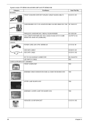
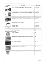
... Category BOARDS Part Name FRONT IO BOARD CENTURY W/AUDIO CABLE*1&USB CABLE*2 Acer Part No. 55.SC101.001 CARD READER 9 IN 1 8.5L AU6476 W/USB2.0 & USB CABLE W/O 1394 CR.10400.107 CABLES WIRELESS LAN BOARD 802.11BGN LITEON WN7600R VGA CARD PCPARTNER 288-1N141-A00AC NVIDIA GT315 512MB SDDR3 DVI+HDMI ATX (SAMSUNG) NI.10200.009 VG.PCPT3.154 POWER CORD 250V 3PIN 1800MM UK 27.01518.181 ODD SATA CABLE HDD SATA CABLE DVI TO VGA DONGLE CONNECTOR LED SWITCH CABLE CASE/COVER...
... Category BOARDS Part Name FRONT IO BOARD CENTURY W/AUDIO CABLE*1&USB CABLE*2 Acer Part No. 55.SC101.001 CARD READER 9 IN 1 8.5L AU6476 W/USB2.0 & USB CABLE W/O 1394 CR.10400.107 CABLES WIRELESS LAN BOARD 802.11BGN LITEON WN7600R VGA CARD PCPARTNER 288-1N141-A00AC NVIDIA GT315 512MB SDDR3 DVI+HDMI ATX (SAMSUNG) NI.10200.009 VG.PCPT3.154 POWER CORD 250V 3PIN 1800MM UK 27.01518.181 ODD SATA CABLE HDD SATA CABLE DVI TO VGA DONGLE CONNECTOR LED SWITCH CABLE CASE/COVER...
Service Guide
Page 96
... BOARDS Part Name FRONT IO BOARD CENTURY W/AUDIO CABLE*1&USB CABLE*2 OEM Part No. 55.SC101.001 CARD READER 9 IN 1 8.5L AU6476 W/USB2.0 & USB CABLE W/O 1394 CR.10400.107 CABLES WIRELESS LAN BOARD 802.11BGN LITEON WN7600R VGA CARD PCPARTNER 288-5N118-A10AC NVIDIA GT320 1GB SDDR3 DVI+HDMI LP (SAMSUNG) NI.10200.009 VG.PCPT3.212 POWER CORD 250V 3PIN 1800MM UK 27.01518.181 ODD SATA CABLE HDD SATA CABLE DVI TO VGA DONGLE CONNECTOR LED SWITCH CABLE CASE/COVER...
... BOARDS Part Name FRONT IO BOARD CENTURY W/AUDIO CABLE*1&USB CABLE*2 OEM Part No. 55.SC101.001 CARD READER 9 IN 1 8.5L AU6476 W/USB2.0 & USB CABLE W/O 1394 CR.10400.107 CABLES WIRELESS LAN BOARD 802.11BGN LITEON WN7600R VGA CARD PCPARTNER 288-5N118-A10AC NVIDIA GT320 1GB SDDR3 DVI+HDMI LP (SAMSUNG) NI.10200.009 VG.PCPT3.212 POWER CORD 250V 3PIN 1800MM UK 27.01518.181 ODD SATA CABLE HDD SATA CABLE DVI TO VGA DONGLE CONNECTOR LED SWITCH CABLE CASE/COVER...
Service Guide
Page 98
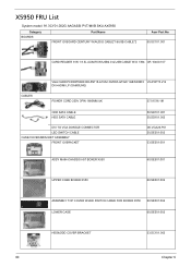
.../MVB SKU AX5950 Category BOARDS Part Name FRONT IO BOARD CENTURY W/AUDIO CABLE*1&USB CABLE*2 Acer Part No. 55.SC101.001 CARD READER 9 IN 1 8.5L AU6476 W/USB2.0 & USB CABLE W/O 1394 CR.10400.107 CABLES VGA CARD PCPARTNER 288-5N118-A10AC NVIDIA GT320 1GB SDDR3 VG.PCPT3.212 DVI+HDMI LP (SAMSUNG) POWER CORD 250V 3PIN 1800MM UK 27.01518.181 ODD SATA CABLE HDD SATA CABLE DVI TO VGA DONGLE CONNECTOR LED SWITCH CABLE CASE/COVER/BRACKET ASSEMBLY FRONT IO...
.../MVB SKU AX5950 Category BOARDS Part Name FRONT IO BOARD CENTURY W/AUDIO CABLE*1&USB CABLE*2 Acer Part No. 55.SC101.001 CARD READER 9 IN 1 8.5L AU6476 W/USB2.0 & USB CABLE W/O 1394 CR.10400.107 CABLES VGA CARD PCPARTNER 288-5N118-A10AC NVIDIA GT320 1GB SDDR3 VG.PCPT3.212 DVI+HDMI LP (SAMSUNG) POWER CORD 250V 3PIN 1800MM UK 27.01518.181 ODD SATA CABLE HDD SATA CABLE DVI TO VGA DONGLE CONNECTOR LED SWITCH CABLE CASE/COVER/BRACKET ASSEMBLY FRONT IO...

Service Guide
Page 104
Keyboard and Input Devices Item Controller Connectors Optical Drive BD Combo Module Item Vendor Model name Drive type Write Speed Specification Super I/O IT8721F • PS2 keyboard and mouse connector • Eleven USB ports (five on front and six on rear) Specification HLDS CH20N BD-Combo DVD-R2x, 4x CLV, 8x ZCLV, 8x PCAV, 12x PCAV, 16x CAV DVD-R DL 2x, 4x CLV DVD-RW2x, 4x, 6x CLV DVD...12x PCAV, 16x CAV DVD-R DL 2x, 4x CLV DVD-RW (SL/DL) 1x, 2x, 4x, 6x CLV / Not support DVD-RAM 2x, 3x CLV, 3-5x PCAV DVD+R 2.4x, 4x CLV, 8x ZCLV, 8x, 12x PCAV, 16x CAV DVD+R DL 2.4x, 4x CLV DVD+RW (SL/DL) 2....
Keyboard and Input Devices Item Controller Connectors Optical Drive BD Combo Module Item Vendor Model name Drive type Write Speed Specification Super I/O IT8721F • PS2 keyboard and mouse connector • Eleven USB ports (five on front and six on rear) Specification HLDS CH20N BD-Combo DVD-R2x, 4x CLV, 8x ZCLV, 8x PCAV, 12x PCAV, 16x CAV DVD-R DL 2x, 4x CLV DVD-RW2x, 4x, 6x CLV DVD...12x PCAV, 16x CAV DVD-R DL 2x, 4x CLV DVD-RW (SL/DL) 1x, 2x, 4x, 6x CLV / Not support DVD-RAM 2x, 3x CLV, 3-5x PCAV DVD+R 2.4x, 4x CLV, 8x ZCLV, 8x, 12x PCAV, 16x CAV DVD+R DL 2.4x, 4x CLV DVD+RW (SL/DL) 2....


