Quick Start Guide
Page 5
...get started with language such as "only for certain models". Follow these steps to complete the installation. Follow the instructions on such subjects as using the keyboard and audio, etc. This guide contains detailed information on the screen to access it contains ...warranty information and the general regulations and safety notices for meeting your computer. Your guides To help you for making an Acer notebook your choice for your notebook. The Aspire...
...get started with language such as "only for certain models". Follow these steps to complete the installation. Follow the instructions on such subjects as using the keyboard and audio, etc. This guide contains detailed information on the screen to access it contains ...warranty information and the general regulations and safety notices for meeting your computer. Your guides To help you for making an Acer notebook your choice for your notebook. The Aspire...
Service Guide
Page 7
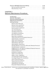
...-line Memory Module) Module Removal . . . .3-22 DIMM Module Installation 3-22 Keyboard Removal 3-23 Keyboard Installation 3-24 Upper Cover Removal 3-25 Upper Cover Installation 3-27 Touchpad Board FFC Removal 3-28 Touchpad Board FFC Installation 3-29 Power Board Removal 3-30 Power Board Installation 3-30 USB Module Removal 3-31 USB Module Installation 3-32 Bluetooth Module Removal 3-33 http://mycomp.su vа...
...-line Memory Module) Module Removal . . . .3-22 DIMM Module Installation 3-22 Keyboard Removal 3-23 Keyboard Installation 3-24 Upper Cover Removal 3-25 Upper Cover Installation 3-27 Touchpad Board FFC Removal 3-28 Touchpad Board FFC Installation 3-29 Power Board Removal 3-30 Power Board Installation 3-30 USB Module Removal 3-31 USB Module Installation 3-32 Bluetooth Module Removal 3-33 http://mycomp.su vа...
Service Guide
Page 8
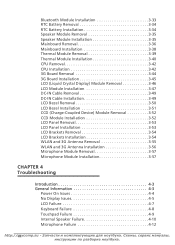
... LCD Panel Removal 3-53 LCD Panel Installation 3-53 LCD Brackets Removal 3-54 LCD Brackets Installation 3-54 WLAN and 3G Antenna Removal 3-55 WLAN and 3G Antenna Installation 3-56 Microphone Module Removal 3-57 Microphone Module Installation 3-57 CHAPTER 4 Troubleshooting Introduction 4-3 General Information 4-3 Power On Issues 4-4 No Display Issues 4-5 LCD Failure 4-7 Keyboard Failure 4-8 Touchpad Failure 4-9 Internal Speaker...
... LCD Panel Removal 3-53 LCD Panel Installation 3-53 LCD Brackets Removal 3-54 LCD Brackets Installation 3-54 WLAN and 3G Antenna Removal 3-55 WLAN and 3G Antenna Installation 3-56 Microphone Module Removal 3-57 Microphone Module Installation 3-57 CHAPTER 4 Troubleshooting Introduction 4-3 General Information 4-3 Power On Issues 4-4 No Display Issues 4-5 LCD Failure 4-7 Keyboard Failure 4-8 Touchpad Failure 4-9 Internal Speaker...
Service Guide
Page 78
...) Module Removal . . . .3-22 DIMM Module Installation 3-22 Keyboard Removal 3-23 Keyboard Installation 3-24 Upper Cover Removal 3-25 Upper Cover Installation 3-27 Touchpad Board FFC Removal 3-28 Touchpad Board FFC Installation 3-29 Power Board Removal 3-30 Power Board Installation 3-30 USB Module Removal 3-31 USB Module Installation 3-32 Bluetooth Module Removal 3-33 Bluetooth Module Installation 3-33 RTC Battery Removal 3-34...
...) Module Removal . . . .3-22 DIMM Module Installation 3-22 Keyboard Removal 3-23 Keyboard Installation 3-24 Upper Cover Removal 3-25 Upper Cover Installation 3-27 Touchpad Board FFC Removal 3-28 Touchpad Board FFC Installation 3-29 Power Board Removal 3-30 Power Board Installation 3-30 USB Module Removal 3-31 USB Module Installation 3-32 Bluetooth Module Removal 3-33 Bluetooth Module Installation 3-33 RTC Battery Removal 3-34...
Service Guide
Page 82
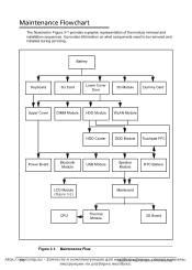
Battery Keyboard 3G Card Lower Cover Door 3G Module Dummy Card Upper Cover DIMM Module HDD Module WLAN Module HDD Carrier ODD Module Touchpad FFC Power Board ... Flow http://3m-6ycomp.su Mуaтcбhуin Figure 3-1 provides a graphic representation of the module removal and installation sequences. It provides information on what components need to be removed and installed during servicing. Maintenance Flowchart 0 The flowchart in кeаM. Сaiхnеteмnaыn,ceс...
Battery Keyboard 3G Card Lower Cover Door 3G Module Dummy Card Upper Cover DIMM Module HDD Module WLAN Module HDD Carrier ODD Module Touchpad FFC Power Board ... Flow http://3m-6ycomp.su Mуaтcбhуin Figure 3-1 provides a graphic representation of the module removal and installation sequences. It provides information on what components need to be removed and installed during servicing. Maintenance Flowchart 0 The flowchart in кeаM. Сaiхnеteмnaыn,ceс...

Service Guide
Page 100
...;eсduмreаsнуалы, Remove keyboard FPC (B) from mainboard connector (A). Place keyboard frame flush against the upper cover. Flip keyboard frame over until keyboard FPC (B) can be connected to Figure 3-19. 4. Refer to mainboard connector (A) (Figure 3-20). 3. Keyboard Installation 0 1. http://3m-2y4comp.su Mуaтcбhуin Figure 3-20...
...;eсduмreаsнуалы, Remove keyboard FPC (B) from mainboard connector (A). Place keyboard frame flush against the upper cover. Flip keyboard frame over until keyboard FPC (B) can be connected to Figure 3-19. 4. Refer to mainboard connector (A) (Figure 3-20). 3. Keyboard Installation 0 1. http://3m-2y4comp.su Mуaтcбhуin Figure 3-20...

Service Guide
Page 103
... secure seven (7) screws (B), two (2) screws (C), and one (1) screw (D) to upper cover. 9. Turn computer over to show lower cover. 3. Install Keyboard. Install and secure five (5) screws (A) in Figure 3-25. Install Base door. 10. Size M2.0x3.0 Quantity 5 Screw Type M2.5x8.0 9 M2.5x4 7 http://MmaychcinoemMpa.instuena-nЗceаPпrчocаeсdт...
... secure seven (7) screws (B), two (2) screws (C), and one (1) screw (D) to upper cover. 9. Turn computer over to show lower cover. 3. Install Keyboard. Install and secure five (5) screws (A) in Figure 3-25. Install Base door. 10. Size M2.0x3.0 Quantity 5 Screw Type M2.5x8.0 9 M2.5x4 7 http://MmaychcinoemMpa.instuena-nЗceаPпrчocаeсdт...


