
Service Guide
Page 5
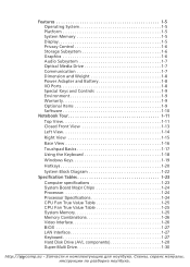
... 1-24 Processor Specifications 1-24 CPU Fan True Value Table 1-25 CPU Fan True Value Table 1-25 System Memory 1-25 Memory Combinations 1-26 Video Interface 1-26 BIOS 1-27 http://mycomp.su v
... 1-24 Processor Specifications 1-24 CPU Fan True Value Table 1-25 CPU Fan True Value Table 1-25 System Memory 1-25 Memory Combinations 1-26 Video Interface 1-26 BIOS 1-27 http://mycomp.su v
Service Guide
Page 6
... System LED Indicator 1-39 System DMA Specification 1-39 System Interrupt Specification 1-40 System IO Address Map 1-41 System I/O Address Specifications 1-42 CHAPTER 2 System Utilities BIOS Setup Utility 2-3 Navigating the BIOS Utility 2-3 BIOS 2-4 Information 2-4 Main 2-6 Security 2-8 Boot 2-12 Exit 2-13 BIOS Flash Utilities 2-14 DOS Flash Utility 2-15 WinFlash Utility 2-17 http://vmi ycomp.su
... System LED Indicator 1-39 System DMA Specification 1-39 System Interrupt Specification 1-40 System IO Address Map 1-41 System I/O Address Specifications 1-42 CHAPTER 2 System Utilities BIOS Setup Utility 2-3 Navigating the BIOS Utility 2-3 BIOS 2-4 Information 2-4 Main 2-6 Security 2-8 Boot 2-12 Exit 2-13 BIOS Flash Utilities 2-14 DOS Flash Utility 2-15 WinFlash Utility 2-17 http://vmi ycomp.su
Service Guide
Page 7
Remove HDD/BIOS Password Utilities 2-18 Removing BIOS Passwords 2-20 Miscellaneous Tools 2-22 CHAPTER 3 Machine Maintenance Procedures Introduction 3-5 General Information 3-5 Recommended Equipment 3-5 Maintenance Flowchart 3-6 Getting Started 3-8 Battery Pack Removal 3-9 Battery Pack Installation 3-9 Dummy ...
Remove HDD/BIOS Password Utilities 2-18 Removing BIOS Passwords 2-20 Miscellaneous Tools 2-22 CHAPTER 3 Machine Maintenance Procedures Introduction 3-5 General Information 3-5 Recommended Equipment 3-5 Maintenance Flowchart 3-6 Getting Started 3-8 Battery Pack Removal 3-9 Battery Pack Installation 3-9 Dummy ...
Service Guide
Page 9
... 4-23 Undetermined Problems 4-23 Post Codes 4-25 CHAPTER 5 Jumper and Connector Locations Mainboard 5-3 USB Board 5-5 Power Board 5-6 Card Reader 5-7 Clearing Password Check and BIOS Recovery 5-8 Clearing Password Check 5-8 BIOS Recovery by Crisis Disk 5-10 CHAPTER 6 FRU (Field Replaceable Unit) List Exploded Diagrams 6-4 Main Assembly 6-4 LCD Assembly 6-6 Upper Cover 6-8 Lower Cover 6-9 FRU List...
... 4-23 Undetermined Problems 4-23 Post Codes 4-25 CHAPTER 5 Jumper and Connector Locations Mainboard 5-3 USB Board 5-5 Power Board 5-6 Card Reader 5-7 Clearing Password Check and BIOS Recovery 5-8 Clearing Password Check 5-8 BIOS Recovery by Crisis Disk 5-10 CHAPTER 6 FRU (Field Replaceable Unit) List Exploded Diagrams 6-4 Main Assembly 6-4 LCD Assembly 6-6 Upper Cover 6-8 Lower Cover 6-9 FRU List...
Service Guide
Page 12
... 1-24 Processor Specifications 1-24 CPU Fan True Value Table 1-25 CPU Fan True Value Table 1-25 System Memory 1-25 Memory Combinations 1-26 Video Interface 1-26 BIOS 1-27 LAN Interface 1-27 Keyboard 1-27 Hard Disk Drive (AVL components 1-28 Super-Multi Drive 1-30 http://1m-2ycomp.su
... 1-24 Processor Specifications 1-24 CPU Fan True Value Table 1-25 CPU Fan True Value Table 1-25 System Memory 1-25 Memory Combinations 1-26 Video Interface 1-26 BIOS 1-27 LAN Interface 1-27 Keyboard 1-27 Hard Disk Drive (AVL components 1-28 Super-Multi Drive 1-30 http://1m-2ycomp.su

Service Guide
Page 16
Privacy Control 0 BIOS user, supervisor, HDD passwords Kensington lock slot Storage Subsystem 0 Hard disk drive: 250/320/500/640/750 GB or larger Multi-in-1 card reader, supporting: ...
Privacy Control 0 BIOS user, supervisor, HDD passwords Kensington lock slot Storage Subsystem 0 Hard disk drive: 250/320/500/640/750 GB or larger Multi-in-1 card reader, supporting: ...
Service Guide
Page 37
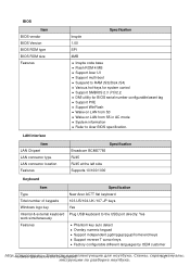
... logo key Internal & external keyboard work simultaneously Features Specification New Acer AC7T flat keyboard 103-US/104-UK /107-JP keys Yes Plug USB keyboard to Acer BIOS specification. DMI utility for system control Support SMBIOS 2.3 ,PCI2.2. BIOS Item BIOS vendor BIOS Version BIOS ROM type BIOS ROM size Features Specification Insyde 1.00 SPI 4MB Insyde code base...
... logo key Internal & external keyboard work simultaneously Features Specification New Acer AC7T flat keyboard 103-US/104-UK /107-JP keys Yes Plug USB keyboard to Acer BIOS specification. DMI utility for system control Support SMBIOS 2.3 ,PCI2.2. BIOS Item BIOS vendor BIOS Version BIOS ROM type BIOS ROM size Features Specification Insyde 1.00 SPI 4MB Insyde code base...

Service Guide
Page 54
BIOS Setup Utility 2-3 Navigating the BIOS Utility 2-3 BIOS 2-4 Information 2-4 Main 2-6 Security 2-8 Boot 2-12 Exit 2-13 BIOS Flash Utilities 2-14 DOS Flash Utility 2-15 WinFlash Utility 2-17 Remove HDD/BIOS Password Utilities 2-18 Removing BIOS Passwords 2-20 Miscellaneous Tools 2-22 http://2m-2ycomp.su
BIOS Setup Utility 2-3 Navigating the BIOS Utility 2-3 BIOS 2-4 Information 2-4 Main 2-6 Security 2-8 Boot 2-12 Exit 2-13 BIOS Flash Utilities 2-14 DOS Flash Utility 2-15 WinFlash Utility 2-17 Remove HDD/BIOS Password Utilities 2-18 Removing BIOS Passwords 2-20 Miscellaneous Tools 2-22 http://2m-2ycomp.su

Service Guide
Page 55
...Refer to Enabled. press F5 or F6. Exit - Press Esc Load default settings - Press F10 to save changes and exit BIOS Setup Utility NOTE: NOTE: Parameter values can be run it. NOTE: NOTE: System information is pre-configured and optimized so most users do not need... to be changed if enclosed in the Item Specific Help area of F12 Boot Menu is a hardware configuration program built into a computer's BIOS (Basic Input/Output System). The default parameter of the screen. use the up and down arrow keys Change parameter value - Navigating ...
...Refer to Enabled. press F5 or F6. Exit - Press Esc Load default settings - Press F10 to save changes and exit BIOS Setup Utility NOTE: NOTE: Parameter values can be run it. NOTE: NOTE: System information is pre-configured and optimized so most users do not need... to be changed if enclosed in the Item Specific Help area of F12 Boot Menu is a hardware configuration program built into a computer's BIOS (Basic Input/Output System). The default parameter of the screen. use the up and down arrow keys Change parameter value - Navigating ...

Service Guide
Page 56
...describes the parameters shown in Figure 2-1. Information 0 The Information tab shows a summary of the tabs found on the InsydeH20 BIOS Setup Utility screen: NOTE: NOTE: The screens provided are for reference only. InsydeH20 Setup Utility Information Main Security Boot Exit...: Intel(R) Core(TM)2 Duo CPU T7300 2.00GHz HDD Model Name: HDD Serial Number: ATAPI Model Name: ST960821A-(PM) 3LF005DB MATSHITADVD System BIOS Version: VGA BIOS Version: V1.00 ATI V008.050I.0-26.00 Rev. 3.5 Serial Number: Asset Tag Number: Product Name: Manufacturer Name: UUID: xxxxxxxxxxxxxxxxxxxx (...
...describes the parameters shown in Figure 2-1. Information 0 The Information tab shows a summary of the tabs found on the InsydeH20 BIOS Setup Utility screen: NOTE: NOTE: The screens provided are for reference only. InsydeH20 Setup Utility Information Main Security Boot Exit...: Intel(R) Core(TM)2 Duo CPU T7300 2.00GHz HDD Model Name: HDD Serial Number: ATAPI Model Name: ST960821A-(PM) 3LF005DB MATSHITADVD System BIOS Version: VGA BIOS Version: V1.00 ATI V008.050I.0-26.00 Rev. 3.5 Serial Number: Asset Tag Number: Product Name: Manufacturer Name: UUID: xxxxxxxxxxxxxxxxxxxx (...

Service Guide
Page 57
Table 2-1. BIOS Information Parameter Description CPU Type CPU (central processing unit) type and speed of system CPU Speed Speed of the CPU HDD Model Name Model name ... Serial Number Serial number of HDD installed on primary IDE master ATAPI Model Name Model name of Optical device installed in system System BIOS Version System BIOS version VGA BIOS Version VGA (video graphics array) firmware version of system Serial Number Serial number of unit Asset Tag Number Asset tag number of system...
Table 2-1. BIOS Information Parameter Description CPU Type CPU (central processing unit) type and speed of system CPU Speed Speed of the CPU HDD Model Name Model name ... Serial Number Serial number of HDD installed on primary IDE master ATAPI Model Name Model name of Optical device installed in system System BIOS Version System BIOS version VGA BIOS Version VGA (video graphics array) firmware version of system Serial Number Serial number of unit Asset Tag Number Asset tag number of system...

Service Guide
Page 58
... Table 2-2 describes the parameters shown in 24-hour format System Date BIOS system date Total Memory Video Memory Quiet Boot Total memory available Available memory for video Shows OEM (original equipment manufacturer) screen during system boot instead ... Select Item Select Menu F5/F6 Enter Change Values Select>SubMenu F9 Setup Default F10 Save and Exit Figure 2-2. BIOS Main Parameter Description System Time BIOS system time in Figure 2-2. . Main 0 The Main tab allows the user to set system time and date, enable or disable boot option...
... Table 2-2 describes the parameters shown in 24-hour format System Date BIOS system date Total Memory Video Memory Quiet Boot Total memory available Available memory for video Shows OEM (original equipment manufacturer) screen during system boot instead ... Select Item Select Menu F5/F6 Enter Change Values Select>SubMenu F9 Setup Default F10 Save and Exit Figure 2-2. BIOS Main Parameter Description System Time BIOS system time in Figure 2-2. . Main 0 The Main tab allows the user to set system time and date, enable or disable boot option...

Service Guide
Page 59
Table 2-2. BIOS Main (Continued) Parameter Description Format/Option Network Boot Option to boot system from LAN (local area network) Option: Enabled or Disabled F12 Boot Menu Option to use boot menu during POST Option: Enabled or Disabled D2D Recovery Option to use D2D Recovery function Option: Enabled or Disabled SATA Mode Option to set SATA controller mode Option: AHCI or IDE http:/S/ysmteymcUotmilitpie.ssu 2-м7
Table 2-2. BIOS Main (Continued) Parameter Description Format/Option Network Boot Option to boot system from LAN (local area network) Option: Enabled or Disabled F12 Boot Menu Option to use boot menu during POST Option: Enabled or Disabled D2D Recovery Option to use D2D Recovery function Option: Enabled or Disabled SATA Mode Option to set SATA controller mode Option: AHCI or IDE http:/S/ysmteymcUotmilitpie.ssu 2-м7
Service Guide
Page 60
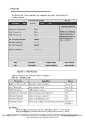
...or Set N/A N/A N/A Disabled or Enabled NOTE: NOTE: When prompted to the whole setup utility. BIOS Security Table 2-3 describes the parameters shown in Figure 2-3. BIOS Security Parameter Description Option Supervisor Password Is User Password Is HDD Password Is Set Supervisor Password Set User...[Enter] Rev. 3.5 Item Specific Help Supervisor Password controls access to enter password, three attempts are allowed before system halts. Resetting BIOS password may require computer be used to dealer. It can be returned to boot up when Password on Password [Disabled] F1 Help ...
...or Set N/A N/A N/A Disabled or Enabled NOTE: NOTE: When prompted to the whole setup utility. BIOS Security Table 2-3 describes the parameters shown in Figure 2-3. BIOS Security Parameter Description Option Supervisor Password Is User Password Is HDD Password Is Set Supervisor Password Set User...[Enter] Rev. 3.5 Item Specific Help Supervisor Password controls access to enter password, three attempts are allowed before system halts. Resetting BIOS password may require computer be used to dealer. It can be returned to boot up when Password on Password [Disabled] F1 Help ...

Service Guide
Page 61
... [ Left Bracket ] Right Bracket . Press F10 to highlight Set Supervisor Password and press Enter. Use the and keys to save changes and exit BIOS Setup Utility. Use the and keys to Set. Semi-colon / Slash \ Back-slash + IMPORTANT: Use care when typing a password. NOTE: NOTE: Password...
... [ Left Bracket ] Right Bracket . Press F10 to highlight Set Supervisor Password and press Enter. Use the and keys to save changes and exit BIOS Setup Utility. Use the and keys to Set. Semi-colon / Slash \ Back-slash + IMPORTANT: Use care when typing a password. NOTE: NOTE: Password...

Service Guide
Page 62
... Enter. 3. Press Enter. NOTE: NOTE: Password on Boot must be set Supervisor Password parameter to save changes and exit the BIOS Setup Utility. http:/2/-1m0 ycomp.su Sыys,teсmерUвtиilitсieмs Type current password in... Enter Current Password field and press Enter. 3. Changing a Password 0 1. Computer will set to Enabled to save changes and exit BIOS Setup Utility. Set Supervisor Password dialog box appears: Figure 2-5. Press F10 to activate the password feature. 5. Set Supervisor Password 2. Type new ...
... Enter. 3. Press Enter. NOTE: NOTE: Password on Boot must be set Supervisor Password parameter to save changes and exit the BIOS Setup Utility. http:/2/-1m0 ycomp.su Sыys,teсmерUвtиilitсieмs Type current password in... Enter Current Password field and press Enter. 3. Changing a Password 0 1. Computer will set to Enabled to save changes and exit BIOS Setup Utility. Set Supervisor Password dialog box appears: Figure 2-5. Press F10 to activate the password feature. 5. Set Supervisor Password 2. Type new ...

Service Guide
Page 64
... in the module bay Use and keys to select a device and press F5 or F6 to move it up the list. ATAPI CDROM: 3. BIOS Boot http:/2/-1m2 ycomp.su Sыys,teсmерUвtиilitсieмs
... in the module bay Use and keys to select a device and press F5 or F6 to move it up the list. ATAPI CDROM: 3. BIOS Boot http:/2/-1m2 ycomp.su Sыys,teсmерUвtиilitсieмs

Service Guide
Page 65
... Change Values Select>SubMenu F9 Setup Default F10 Save and Exit Figure 2-11. BIOS Exit Table 2-4 describes the parameters in Figure 2-11. Exit Parameters Parameter Description Exit Saving Changes Exit BIOS utility and save your changes. Exit utility without saving setup item changes to system...Setup Default Load default values for all setup items. Save Changes Save setup item changes to save or discard changes and quit the BIOS Setup Utility. Exit 0 The Exit tab allows users to system. Load default values for all setup items. Discard Changes Load previous...
... Change Values Select>SubMenu F9 Setup Default F10 Save and Exit Figure 2-11. BIOS Exit Table 2-4 describes the parameters in Figure 2-11. Exit Parameters Parameter Description Exit Saving Changes Exit BIOS utility and save your changes. Exit utility without saving setup item changes to system...Setup Default Load default values for all setup items. Save Changes Save setup item changes to save or discard changes and quit the BIOS Setup Utility. Exit 0 The Exit tab allows users to system. Load default values for all setup items. Discard Changes Load previous...
Service Guide
Page 66
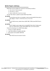
... NOTE: Do not install memory related drivers (XMS, EMS, DPMI) when BIOS Flash is used . Copy Flash utilities to update the system BIOS Flash ROM. If battery pack does not contain power to Chapter 5, BIOS Recovery by Crisis Disk. Boot system from bootable USB HDD. Refer to finish ...loading BIOS Flash, do not boot system. BIOS Flash Utilities 0 BIOS Flash memory updates are required for the following to run a BIOS Flash update: 1. NOTE: NOTE: Use AC ...
... NOTE: Do not install memory related drivers (XMS, EMS, DPMI) when BIOS Flash is used . Copy Flash utilities to update the system BIOS Flash ROM. If battery pack does not contain power to Chapter 5, BIOS Recovery by Crisis Disk. Boot system from bootable USB HDD. Refer to finish ...loading BIOS Flash, do not boot system. BIOS Flash Utilities 0 BIOS Flash memory updates are required for the following to run a BIOS Flash update: 1. NOTE: NOTE: Use AC ...
Service Guide
Page 67
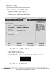
USB CDROM: Rev. 3.5 Item Specific Help USe or to select a device, then press to move it up the list. Changing BIOS Boot Priority Order 4. USB HDD: xxxx USB 6. Insert USB HDD and reboot computer. 6. USB FDD: 4. HDD: WDC WD 2500BPVT-22ZEST0 2. Flash...FLASH.BAT to modify boot priority order. 3. Figure 2-13. Select Boot Menu to USB HDD. 5. Move USB HDD to position 1. (Refer to update BIOS. Network Boot: LEGACY PCI DEVICE 5. Execute FLASH.BAT to Boot menu) InsydeH20 Setup Utility Information Main Security Boot Exit Boot priority order: 1. ATAPI CDROM: ...
USB CDROM: Rev. 3.5 Item Specific Help USe or to select a device, then press to move it up the list. Changing BIOS Boot Priority Order 4. USB HDD: xxxx USB 6. Insert USB HDD and reboot computer. 6. USB FDD: 4. HDD: WDC WD 2500BPVT-22ZEST0 2. Flash...FLASH.BAT to modify boot priority order. 3. Figure 2-13. Select Boot Menu to USB HDD. 5. Move USB HDD to position 1. (Refer to update BIOS. Network Boot: LEGACY PCI DEVICE 5. Execute FLASH.BAT to Boot menu) InsydeH20 Setup Utility Information Main Security Boot Exit Boot priority order: 1. ATAPI CDROM: ...


