
AL2021 Service Guide
Page 2
... implied, with respect to change without the prior written permission of Acer Incorporated. Acer is a registered trademark of Intel Corporation. Other brand and product names are trademarks of Intel Corporation. No part of all necessary servicing, repair, and any incidental or consequential damages resulting from any means, electronic, mechanical, magnetic, optical, chemical, manual or otherwise, without notice...
... implied, with respect to change without the prior written permission of Acer Incorporated. Acer is a registered trademark of Intel Corporation. Other brand and product names are trademarks of Intel Corporation. No part of all necessary servicing, repair, and any incidental or consequential damages resulting from any means, electronic, mechanical, magnetic, optical, chemical, manual or otherwise, without notice...

AL2021 Service Guide
Page 4
... to those given in the printed Service Guide, for ACER-AUTHORIZED SERVICE PROVIDERS, your regional office MAY have a DIFFERENT part number code to order FRU parts for whatever reason, a part number change is made, it supports, please read the following general information. 1. Preface Before using this information and the product it will NOT be noted in the FRU list of customer machines. - 4 - In...
... to those given in the printed Service Guide, for ACER-AUTHORIZED SERVICE PROVIDERS, your regional office MAY have a DIFFERENT part number code to order FRU parts for whatever reason, a part number change is made, it supports, please read the following general information. 1. Preface Before using this information and the product it will NOT be noted in the FRU list of customer machines. - 4 - In...
AL2021 Service Guide
Page 5
... user's authority to qualified personnel only. - 5 - Refer servicing to operate the equipment. 2. Do not open the cabinet. WARNING: (FOR FCC CERTIFIED MODELS) NOTE: this equipment has been tested and found to comply with the limits for a Class B digital device, pursuant to provide reasonable protection against harmful interference in a residential installation. These limits are present inside the monitor. Connect...
... user's authority to qualified personnel only. - 5 - Refer servicing to operate the equipment. 2. Do not open the cabinet. WARNING: (FOR FCC CERTIFIED MODELS) NOTE: this equipment has been tested and found to comply with the limits for a Class B digital device, pursuant to provide reasonable protection against harmful interference in a residential installation. These limits are present inside the monitor. Connect...
AL2021 Service Guide
Page 6
... power source indicated on the monitor. The monitor should be sure these openings are not sure of the type of the grounded plug. Never push any object into a grounded power outlet as a safety feature. Overloading can injure a person and cause serious damage to the appliance. Use only a trolley or stand recommended by the manufacture and follow the kit instructions. The monitor...
... power source indicated on the monitor. The monitor should be sure these openings are not sure of the type of the grounded plug. Never push any object into a grounded power outlet as a safety feature. Overloading can injure a person and cause serious damage to the appliance. Use only a trolley or stand recommended by the manufacture and follow the kit instructions. The monitor...

AL2021 Service Guide
Page 7
... of the LCD screen, an afterimage of the fluorescent light, the screen may remain after switching the image, when the same image is recovered slowly by changing the image or turning off the Power Switch for hours. You may find slightly uneven brightness in the screen depending on again to the nature of the previous screen may flicker during initial use . NOTES Due to make sure the flicker disappears.
... of the LCD screen, an afterimage of the fluorescent light, the screen may remain after switching the image, when the same image is recovered slowly by changing the image or turning off the Power Switch for hours. You may find slightly uneven brightness in the screen depending on again to the nature of the previous screen may flicker during initial use . NOTES Due to make sure the flicker disappears.
AL2021 Service Guide
Page 9
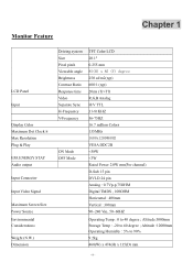
Monitor Feature Chapter 1 LCD Panel Input Display Color Maximum Dot Clock ® Max Resolution Plug & Play EPA ENERGY STAY Audio output Input Connector Input Video Signal Maximum Screen Size Power Source Environmental Considerations Weight (N.W.) Dimension Driving system Size Pixel pitch Viewable angle Brightness Contrast Ratio Response time Video Separate Sync H-Frequency V-Frequency ON Mode OFF Mode TFT Color LCD 20.1" 0.255 mm 85(H) x 85 (V) degree 250 cd/m2(typ) 600:1 (typ) 20ms (Tr+Tf) R,G,B Analog H/V TTL 31-81KHZ 56-75HZ 16.7 million Colors 135MHz 1600x1200@60HZ VESA DDC2B
Monitor Feature Chapter 1 LCD Panel Input Display Color Maximum Dot Clock ® Max Resolution Plug & Play EPA ENERGY STAY Audio output Input Connector Input Video Signal Maximum Screen Size Power Source Environmental Considerations Weight (N.W.) Dimension Driving system Size Pixel pitch Viewable angle Brightness Contrast Ratio Response time Video Separate Sync H-Frequency V-Frequency ON Mode OFF Mode TFT Color LCD 20.1" 0.255 mm 85(H) x 85 (V) degree 250 cd/m2(typ) 600:1 (typ) 20ms (Tr+Tf) R,G,B Analog H/V TTL 31-81KHZ 56-75HZ 16.7 million Colors 135MHz 1600x1200@60HZ VESA DDC2B

AL2021 Service Guide
Page 10
Switch Function External Controls : Regulatory Compliance * Power Switch * MENU/ENTER * >/ Volume *
Switch Function External Controls : Regulatory Compliance * Power Switch * MENU/ENTER * >/ Volume *
AL2021 Service Guide
Page 15
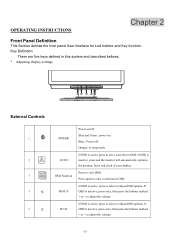
... INSTRUCTIONS Chapter 2 Front Panel Definition This Section defines the front panel User Interface for Led Indictor and Key function. Press again to exit a selection in OSD. Key Definition: There are five keys defined in this system and described bellows. * Adjusting display settings External Controls 1. 2 3 4 < 5 > POWER AUTO OSD Function MINUS PLUS Power on/off Blue and Green : power on Blue : Power off Orange: in sleep mode If OSD is active, press to adjust the volume...
... INSTRUCTIONS Chapter 2 Front Panel Definition This Section defines the front panel User Interface for Led Indictor and Key function. Press again to exit a selection in OSD. Key Definition: There are five keys defined in this system and described bellows. * Adjusting display settings External Controls 1. 2 3 4 < 5 > POWER AUTO OSD Function MINUS PLUS Power on/off Blue and Green : power on Blue : Power off Orange: in sleep mode If OSD is active, press to adjust the volume...

AL2021 Service Guide
Page 16
V-Position: This adjusts the vertical. It also changes the size of the picture on the background of the screen this renders them less noticeable by minimizing their size. Brightness: This adjusts the brightness of the horizontal screen. Clock: If there are three ways of adjusting color: Warm (Reddish white) Cool (Bluish white) User defined: You can adjust the colors red, green and blue to achieve a comfortable contrast. OSD Menu Contrast: This adjusts dark and light shades of color relative to each...
V-Position: This adjusts the vertical. It also changes the size of the picture on the background of the screen this renders them less noticeable by minimizing their size. Brightness: This adjusts the brightness of the horizontal screen. Clock: If there are three ways of adjusting color: Warm (Reddish white) Cool (Bluish white) User defined: You can adjust the colors red, green and blue to achieve a comfortable contrast. OSD Menu Contrast: This adjusts dark and light shades of color relative to each...
AL2021 Service Guide
Page 17
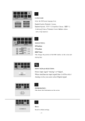
OSD SETTING: H-Position V-Position OSD Timer This changes the position of the OSD window on the screen. Reset: Recall to select Digital signal. INPUT SIGNAL SELECTION : Detect input signal "Analog" or "Digital . INFORMATION: This shows brief information on the screen and staying time. When simultaneous input signal then it will be select Analog or else you can to default settings. - 17 - LANGUAGE: Select the OSD menu language from English-English, Deutsch -German, Espanol-Spanish Simplified Chinese Traditional Chinese, Francais -French, Italiano -Italian...
OSD SETTING: H-Position V-Position OSD Timer This changes the position of the OSD window on the screen. Reset: Recall to select Digital signal. INPUT SIGNAL SELECTION : Detect input signal "Analog" or "Digital . INFORMATION: This shows brief information on the screen and staying time. When simultaneous input signal then it will be select Analog or else you can to default settings. - 17 - LANGUAGE: Select the OSD menu language from English-English, Deutsch -German, Espanol-Spanish Simplified Chinese Traditional Chinese, Francais -French, Italiano -Italian...
AL2021 Service Guide
Page 18
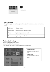
Exit: Exit from OSD. LED Definition The system equips one dual color (green/amber) led to indict system status and defined as bellows : LED Color System Status Green + Blue System in normal operation mode Amber System in power-saving mode Dark System in power-off mode Factory Mode Setting Hot Key: Auto button + Power Button Indicator : The LED of Power is Amber These pages are only visible in factory mode for service people using R, G, B OFFSET: Adjust current RGB cut off level R, G, B GAIN: Adjust current RGB Driver value. - 18 -
Exit: Exit from OSD. LED Definition The system equips one dual color (green/amber) led to indict system status and defined as bellows : LED Color System Status Green + Blue System in normal operation mode Amber System in power-saving mode Dark System in power-off mode Factory Mode Setting Hot Key: Auto button + Power Button Indicator : The LED of Power is Amber These pages are only visible in factory mode for service people using R, G, B OFFSET: Adjust current RGB cut off level R, G, B GAIN: Adjust current RGB Driver value. - 18 -
AL2021 Service Guide
Page 19
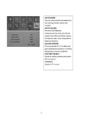
AUTO BURN: Use the chip set internal signal. FACTORY RESET: Recall to initial all other color temperature detail parameters. AUTO COLOR: Perform Auto Balance measurement by chip set internal pattern for hot running monitor panel and inverter. VERSION: Display F/W version - 19 - And reference these values to factory setting and power off immediately. COLOR UPDATE: Force presently R, G, B offset and gain parameters update to currently temperature memory address.
AUTO BURN: Use the chip set internal signal. FACTORY RESET: Recall to initial all other color temperature detail parameters. AUTO COLOR: Perform Auto Balance measurement by chip set internal pattern for hot running monitor panel and inverter. VERSION: Display F/W version - 19 - And reference these values to factory setting and power off immediately. COLOR UPDATE: Force presently R, G, B offset and gain parameters update to currently temperature memory address.

AL2021 Service Guide
Page 20
... monitor meets the Green monitor standards as set by pressing a key on the I2C protocol. The host can request EDID information over the DDC2B channel. HOW TO OPTIMIZE THE DOS-MODE Plug and play Plug & play DDC2B feature This monitor is equipped with VESA DDC2B capabilities according to a "Screen Saver" feature except the display is automatically redrawn. After the video input signal is restored, full power...
... monitor meets the Green monitor standards as set by pressing a key on the I2C protocol. The host can request EDID information over the DDC2B channel. HOW TO OPTIMIZE THE DOS-MODE Plug and play Plug & play DDC2B feature This monitor is equipped with VESA DDC2B capabilities according to a "Screen Saver" feature except the display is automatically redrawn. After the video input signal is restored, full power...

AL2021 Service Guide
Page 21
... UL listed and CSA labeled. The other end terminates with units intended for the power cord shall be 125 volt AC. Supplied with a molded-on type connector body, rated 10A, 250V, having standard CEE-22 female configuration. Please note that power supply card needs to power outlet of personal computer: Please use VDE 0602, 0625, 0821 approval power cord in European counties. - 21 -
... UL listed and CSA labeled. The other end terminates with units intended for the power cord shall be 125 volt AC. Supplied with a molded-on type connector body, rated 10A, 250V, having standard CEE-22 female configuration. Please note that power supply card needs to power outlet of personal computer: Please use VDE 0602, 0625, 0821 approval power cord in European counties. - 21 -

AL2021 Service Guide
Page 22
Front View : ( unit : mm ) Real View : - 22 - Note : The monitor surface is susceptible to avoid mismatch when putting back the components. 2. During the disassembly process, group the screws with the corresponding to scratching! Therefore, lay the monitor on how to assemble the monitor for the different components vary in size. Wear gloves. The screws for maintenance and trouble shooting NOTE : 1. Chapter 3 Machine Assembly This chapter contains step-by-step procedures on a soft surface when mounting or removing the base. 3.
Front View : ( unit : mm ) Real View : - 22 - Note : The monitor surface is susceptible to avoid mismatch when putting back the components. 2. During the disassembly process, group the screws with the corresponding to scratching! Therefore, lay the monitor on how to assemble the monitor for the different components vary in size. Wear gloves. The screws for maintenance and trouble shooting NOTE : 1. Chapter 3 Machine Assembly This chapter contains step-by-step procedures on a soft surface when mounting or removing the base. 3.
AL2021 Service Guide
Page 28
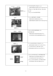
... FRAME by screw (MM30040IBJ9 SCREW M3.0*4.0-I(NI) Q'TY:4) 2. Fix the PORT BKT on FRAME (FBL0T005019 PORT BKT Q'TY:1) (MM30040IBJ9 SCREW M3.0*4.0-I(NI) Q'TY:2) 1.Stick the MYLAR(POWER) on the MAIN-BD-ESD (FBL0T002010 MAIN-BD-ESD Q'TY:1) ( FCL0T002011 MYLAR(POWER) Q'TY:1) 1.Fix the MAIN-BD-ESD on Frame by screw (MM30040IBJ9 SCREW M3.0*4.0-I (NI) Q'TY) 1. 1. Plug in the Cable MB-LCD (Note: white point face...
... FRAME by screw (MM30040IBJ9 SCREW M3.0*4.0-I(NI) Q'TY:4) 2. Fix the PORT BKT on FRAME (FBL0T005019 PORT BKT Q'TY:1) (MM30040IBJ9 SCREW M3.0*4.0-I(NI) Q'TY:2) 1.Stick the MYLAR(POWER) on the MAIN-BD-ESD (FBL0T002010 MAIN-BD-ESD Q'TY:1) ( FCL0T002011 MYLAR(POWER) Q'TY:1) 1.Fix the MAIN-BD-ESD on Frame by screw (MM30040IBJ9 SCREW M3.0*4.0-I (NI) Q'TY) 1. 1. Plug in the Cable MB-LCD (Note: white point face...

AL2021 Service Guide
Page 35
DVI-D Digital Receptacle Connector x 1 26 CN8 DVI-I GND C5 HS C4 BLU RED ... of the 24 pin DVI-D connector / cable is as follows : PIN Signal 1 TMDS data2- (RX2-) 2 TMDS data2+ (RX2+) 3 TMDS data2 shield (GND) 4 NC 5 NC 6 DDC clock (SCL) 7 DDC data (SDA) 8 Not connected 9 TMDS data1- (...RX1-) 10 TMDS data1+ (RX1+) 11 TMDS data1 shield (GND) 12 NC 13 NC 14 +5V 15 Ground (return for +5 V and H/V sync) 16 Hot plug...
DVI-D Digital Receptacle Connector x 1 26 CN8 DVI-I GND C5 HS C4 BLU RED ... of the 24 pin DVI-D connector / cable is as follows : PIN Signal 1 TMDS data2- (RX2-) 2 TMDS data2+ (RX2+) 3 TMDS data2 shield (GND) 4 NC 5 NC 6 DDC clock (SCL) 7 DDC data (SDA) 8 Not connected 9 TMDS data1- (...RX1-) 10 TMDS data1+ (RX1+) 11 TMDS data1 shield (GND) 12 NC 13 NC 14 +5V 15 Ground (return for +5 V and H/V sync) 16 Hot plug...
AL2021 Service Guide
Page 36
... Service Guide. For whatever reasons a part number change is made, it , or follow the rules set by your regional Acer office on how best to dispose it will not be noted in the printed Service Guide. Chapter 6 FRU (Field Replaceable Unit) list This chapter gives you the FRU (Field Replaceable Unit) listing in global configurations of customer machines. Refer to order FRU parts repair...
... Service Guide. For whatever reasons a part number change is made, it , or follow the rules set by your regional Acer office on how best to dispose it will not be noted in the printed Service Guide. Chapter 6 FRU (Field Replaceable Unit) list This chapter gives you the FRU (Field Replaceable Unit) listing in global configurations of customer machines. Refer to order FRU parts repair...

AL2021 Service Guide
Page 42
... from respective RGB series Capacitors GNDGNDGND R94 0/6 U11 1 2 1A 3 4 1Y 2A 2Y 5 6 3A 8 9 3Y 4Y 4A 6A 13 12 6B 5A 5B 11 10 VCC GND 14 7 SN74LVC14A/NS C107 0.1uF/6 GNDGND AHS 4 AVS 4 +3.3V PROJECT : L0T Quanta Computer Inc. Title 03. Graphic Inputs Size Date: Document Number 03. The rest of 8 - 42 - DVI CONNECTOR CN8 25...
... from respective RGB series Capacitors GNDGNDGND R94 0/6 U11 1 2 1A 3 4 1Y 2A 2Y 5 6 3A 8 9 3Y 4Y 4A 6A 13 12 6B 5A 5B 11 10 VCC GND 14 7 SN74LVC14A/NS C107 0.1uF/6 GNDGND AHS 4 AVS 4 +3.3V PROJECT : L0T Quanta Computer Inc. Title 03. Graphic Inputs Size Date: Document Number 03. The rest of 8 - 42 - DVI CONNECTOR CN8 25...

AL2021 Service Guide
Page 45
...Size Date: 06. Memory I /F Friday, July 11, 2003 L0T Rev 1A Sheet 6 of 8 - 45 - Memory I /F Document Number 06. +3.3V_DIG R40 10K/6 R43 10K/6 R67 10K/6 4 /OCM_WE 4 /OCM_RE 4 /ROM_CS /OCM_WE /OCM_RE /OCM_CS +3.3V_DIG GND 4 OCMADDR[0..19] 4 OCMDATA[0..7] OCMDATA[0..7] OCMADDR[0..19] C60 22uF/25V C59 0.1uF/6 Socket for a X8 Flash... 8-BIT_FLASH3 TCLK OUTPUTS_ZERO OUTPUTS_ZERO GND GND 10: LOW (Use TCLK) 11: LOW (set all display output to '0') 12: LOW 13: LOW(disable serial interface debug) 14: LOW 15: LOW 16: HIGH (use crystal) 17: LOW (8bit bus with OCM access external...
...Size Date: 06. Memory I /F Friday, July 11, 2003 L0T Rev 1A Sheet 6 of 8 - 45 - Memory I /F Document Number 06. +3.3V_DIG R40 10K/6 R43 10K/6 R67 10K/6 4 /OCM_WE 4 /OCM_RE 4 /ROM_CS /OCM_WE /OCM_RE /OCM_CS +3.3V_DIG GND 4 OCMADDR[0..19] 4 OCMDATA[0..7] OCMDATA[0..7] OCMADDR[0..19] C60 22uF/25V C59 0.1uF/6 Socket for a X8 Flash... 8-BIT_FLASH3 TCLK OUTPUTS_ZERO OUTPUTS_ZERO GND GND 10: LOW (Use TCLK) 11: LOW (set all display output to '0') 12: LOW 13: LOW(disable serial interface debug) 14: LOW 15: LOW 16: HIGH (use crystal) 17: LOW (8bit bus with OCM access external...


